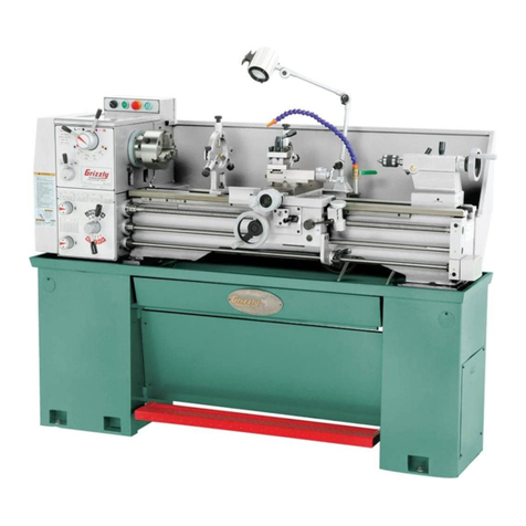
CLAUSING 5910 Series User manual

I
·-
i.:
_;
' /
; 1 -
.·
j
/
l '
·'
-
_..,
S
/tJ
Jo
fo
--t;;_
~JI
C&
'I
I l !
. I
I
I
DE
·
ALER'S
MASTER
,,
....
.
PA
.
RT
.S·
MANUAL
. k ' .
,.
;;.,, .
···- Series
Two
CLAUSING
12-inch ·LATHES-5910-series
,
.,..
-
-
~·
A~1i~~,
t'r:t°d~".14
1 •
r
~'•"
"(
;"" :
~
'~
-.
-~.
'
''-
,
;~
J.
~
~<
.-..,;•·-',':,'
~
>;J":
~f>r.> '
-·
OLAUSING
,
C ' 0 R P O R A T I O N :,,t
. ' '
2019 N.
PIT.CHER
ST., KALAMAZOO, MICH. 49007 ·
·,
,.
-
..
-
• ·
~=-
~
' \
:
I
t
I
I
\
;
!
I
I
. r
l
:I
i 'h
I :!
I ,
!
,i
' '
I.;
i :'
i
I.
, I
: I
!
'
'I
f ·1;
l 1·
I i
;(
I
' ''
' '
I . ;
..
I
I·,,'

CLAUSING
SERVICE
CENTER
811 EISENHOWER DR., SO.
P.O.
BOX
877
GOSHEN, IN
46526
SERVICE & PARTS
MANUAL
MODEL NO. 5914
SERIAL
NO.
SlO?OG
Phone 574-533-0371
Fax
574
-53
3-0403
..
--
-
---
'
' ·
,..
-•
I
I
I
'
•
•
•

■
r~
.c
•,(:
l'
.'
\·· '
•··:..,'
; (1
•. l:J
.. /
'-~
·-
1
•
··
.:
•"L.-i
.{
.r:
~
.. ·
' I
•
f.
I
•...
~
'
1·
,.
,
L.·,
:
. -1)
·
-L
I
, ,. , a
,-l
~!
,c
ftrnz.
• .. : :~
·:
•
··
.:· · : _. .
...
\
SEPTEMBER,
1974
PARTS
INDEX
@
For
Lath!)s
from
Serial
No.
·
s10
IOb
To
:
51
fbl..//.
5910
1
Cabin.?t
. . .. . . . . ... . . . . . . . . . . . . . . . . . . 18.1
Bed
.........
.
....
. . .. . . . . . . . . . . . . . . . . . . . . . . . . . . . . 19
Headstock
Costing
and
Gt:or
Tra
in
Guard
............•.•......•••••••••
20.1
Headstock
......•.........•
. .
Quick-Change
Gear
Box
.....
.
Gear
Train
.•.••....•....
Electrical
Assembly
.
...
...
....
.
. . . . . . . . . . . . . . . .. . .. . . . . . . . . . . .
. . . . . . . . . . . . . . . . . . . . . . . . . . . . . . . 21. 2
22.3
....
.
..
.,.
. . . . . . . . . . . . . . . . . . . .
23
.
......
.
..
..
...
..
.......
24
Countershoft
..•........
.
......
. .
..
..
25.5
26.5
Countershoft
with
Clutch
and
Broke
Motor
Bose
Assembly
..
...•...
Variable
Speed
Control
.
...
. . . .
Variable
Speed
Motor
Pul
Icy
.•....
Cross
SI
ide
.................
.
Carriage
...
...
. .
..
...
.
..
.
Apron
...
......
•...
...
.
..
Toilstock
. . . . . . . . . . . . . . . . . . . . . .
27
· · · · ·
...
.
..........
.
.....
28. l
29.3
. . . . . . . . . . . . . . . . .
30
.
..
.
..
....
.........
.
....
..
.....
31
. . . . . . . . . . . . . . . . . . 32.3 &
33.4
. . . 34.1
INSTRUCTIONS
FOR
ORDERING
REPAIR
PARTS
It
is
i
mportant
to
furn i
sh
the
following
.
information
in
add
i
tion
to
QUANTITY
required
:
1.
PART
NUMBER
2.
PART
NAME
3.
MODEL
and
SERIAL
NUMBER
of
mach
i
ne
tool
-
you
'
ll
fi_
n~th
on the
metal
plate
·
attached
to
mach
i
ne
-
note
illustration
below.
ORDER
REPAIR
PARTS
FROM
CLAUSING SERVICE CENTER
811
EISENHOWER
DRIVE
SOUTH
GOSHEN,
INDIANA
46526
NOTE
:
Screws
and
nuts
shown
without
part
numbers
should
be
pt.1
r
chasecl
locally.
We
reserve
the
ri
ght
to
make
changes·
in
design
·
and
specifications
without
not
i
ce.
17.17
. . .. ..
:
.·
. . ... :
....
..-......
,1"'
·, ~· :
·•
~ :,:
.:
:·
.--~
·-:
::\:
_.·.,
Z.
~~
-
--
--
··
·
--~
...
:.
..
·
.·
.
..
:...
·.
..
,
;_
-:
:
..
.-
..
..
..
;_
.
;,.:-:
• .• ·••
~.:
~
..
,... .

'--·-~·
N
-
VI
'°
lllllli
..
~
~
~
~
~
~
~ -
~
~
~
~
~
~
-
, .
~
--• •
·-
--
,--------.
,--
\ --·.
...
. ·
--
,
.---
· ' ( · ·
-•
--
·-
- :
·i
,
__
;
e,
.-
··
c=: ~-
---
·
L--
'
:_
_
_>
\_ _ _1
r--7
1
:c
,.
/
-;j
L _
__;
:.I~
.3
~
--=-
7
;__,
. L .
.-.:
-~
::
=·J _
..,:
...
.-·-
- · )
__
_,
GENERAL
DIMENSIONS
--
5900
SERIES
CLAUSING
LATHES
,,
29
--
i--~
L....12
\ 7
L
---,
o•~
·o
/0
0
□
0
,___
___
21}'.;-'
---
7
51"
\
'
-~
l=1
D
8
6.0.."
/
72
,,,
.
"----
I
24,,
~CENTERS-I
-·- ·- ·
-·-"
I
·- ·-
n_
c::=::::J
4_4"
24,,
35"
I
1-+l
,---'~
3
....;.
6
....,.,,.,....c
ENTER
47
,,
APPROX.~
---
·
----
19
3
/.;'
APPROX.
1
''1='
,
II
-7·
....
s1/;'
1·
---
·
1-11
·
--
-u
11¾"
I
__ _
,_J_ox.
CLEARANCE
To--i-:--91/~~
1
1a
JI.
"
REMOVE
MOTOR
GUARD
j_
2
APPROX.-----------i
CLEARANCE
TO
OPEN
DOOR
90
}..,"

• I
I
·-
'.
!
,...
. ;
l
i_
-
.i
I
PJ
I
iJ
1Li
' -.
i I
I
~_J
: : 'j
,u
I
'
INSTALLATION
FOUNDATION
Your
Clausing
lathe
is
a
precision
machine
tool,
and
requires
a
solid
foundation.
The
floor
must
be
heavy
enough
to
support
the
weight
of
the
machine
without
noticeable
deflection,
and
it
must
be
level.
If
the
floor
does
not
meet
these
important
requirements,
a
special
foundation
should
be
built.
CONCRETE
FLOORS
- - A
reinforced
concrete
floor
is
the
best
foundation:
it
provides
a
rigid
base,
min-
imizes
vibration
from
adjacent
machines,
and
resists
deflection.
WOOD
FLOORS
should
be
carefully
checked
for
strength
- -
place
a
precision
level
oo
floor where
lathe
is
to
be
located,
and
move a
hand
truck
with
average
load
past
it.
If
bubble
in
level
shows
no-
ticeable
movement,
the
floor
should
be
reinforced,
or
cut
away
and
a
concrete
foundation
installed.
4910
5910
6900
CLEANING
Before
moving carriage
or
tailstock
along
the
ways,
use
a good
grease
solvent
to
remove
the
rust-proof
coating
applied
to
all
polished
and
unpainted
sur-
faces
.
Do
not
.
use
an
air
hose
- -
it
could
force
dirt
or
grit
picked
up
during
transit
into
bearing
surfaces.
Use
a
stiff
bristle
brush
to
clean
lead
screw.
When
thoroughly
cleaned
,
cover
the
unpainted
sur-
faces
with
a
light
coating
of
"Way
Lubricant"
for
proper
lubrication.
Frequent
cleaning
and
lubrication
is
essential
to
long
·
service
life
- -
see
pag
e 5 for
instructions.
MOVING
AND
LIFTING
Leave
lathe
on
skid
- -
simplifies
moving
to
final
location.
IMPORTANT:
DO
NOT
slide
lathe
along
floor,
DO
NOT
USE fork
lift
under
chip
pan.
3.1
APPROXIMATE
LEADSCREW
CENTER
OF
t'EIGHT
PROTECTION
I
FLOOR
F i
gure
1
'
CAUTION:
DO
NOT
LOWER
LEVELING
SCREW
PADS
UNTIL
LATHE
IS
READY
TO
BE
LEVELED
••
refer to figure
I.
When
using
a
sling
- -
clean
bed
ways,
move
t~il-
stock
to
th
e
right-hand
end
of
the
bed
and
lock
it
in
place.
To
protect
lead
screw
and
bed,
p
lac
·e a 3/
4"
thick
hardwood
board
under
approximate
center
of
weight
load,
insert
sling
as
shown
in
figure
·
1,
and
raise
m
ac
hine
about
one-inch
off
floor.
Make
any
necessary
adjustments
for
balance
by
moving
car-
riage
along
bed.
-B
efore
moving carriage, l
oos
en
lock
scr
ew
- •
locat
ed on top
right
side
of
the
car•
riage.
If
a fork
lift
is
u
se
d,
place
3/ 4"
thick
hardwood
board
under
the
bed
so
that
th~
clutch
rod
will
not
be
bent
when the
lathe
is
raised
- - do
not
pick
up
by
chip
pan.
Mounting
pads
do
not
require
anchoring.
Leveling
screws
are
equipped
with
non-slip
mounting
pads
which
eliminate
the
need
for
anchoring
or
bolt
-
ing
machine
to
floor.
Floor
must
be
clean
and
free
of
oil.
.
..
.....
,

l
:,
. ;,.j
I ,
I
,·
·
.u
I
lu
I\I
• I
•
'.
~
J
I .
I·
l -· 1
I ~-
'
I
'·( l
. !
i
1
.u
t:,
..
I.
i.
J
t··~
,.
I
*\
:_
, ~!
;( !
ELECTRICAL
CONNECTIONS
The
machine
is
wired
at
factory
- -
merely
connect
power
supply
to
line
leads
in
junction
box
on
back
of
headstock
cabinet.
IMPORTANT:
To
reverse
ro-
tation
of
motor
interchange
any
two
line
leads
- -
see
WIRING
INSTRUCTIONS
.
Before
connecting
motor,
make
sure
chat
voltage
and
other
current
requirements
of
the
motor
correspond
with
your
power
supply.
If
there
is
any
question,
verify
your
current
and
voltage
by
calling
your
power
company.
ANCHORING
LATHE
TO
FLOOR
CAUTION:
DO
NOT
SLIDE
LATHE
ALONG
FLOOR.
CABINET
ANCHOR
LOCK
BOLT
WASHER
I/
LEVELING
SCREW
FLOOR
'<U£L__J;.t.:J>"'ANCHOR
NUT
Figure
2
Use
anchor
bolts
to
secure
:
fathe
to
concrete
floor - -
use
lag
screws
to
secure
lathe
to
wood
floor
- -
refer
to
figure 2.
With a
hoist
or
lift,
lower
the
lathe
into
position
and
mark the four
leveling
screw
locations.
DO
NOT
LOWER
LEVELING
SCREW PADS.
Lift
machine
out
of
the
way,
drill
holes
for
anchor
nuts
and
install
anchor
nuts
- - for
lag
screws
drill
pilot
holes.
Position
and
lower
machine.
Turn
leveling
screws
until
no portion
of
the
lathe
cabinet
touches
the
floor
--
shim
under
pads,
if
necessary.
Start
anchor
bolts
or
lag
screws
- - DO
NOT
tighten
until
lathe
is
level
- -
see
Leveling
Instructions.
LEVELING
The
lathe
should
be
kept
perfectly
level
at
all
times.
-
When
carelessly
mounted,
the
be.d may
become
twist-
ed.
Even
a
slight
amount
of
twist
will
move
centers
out
of
alignment
and
result
in
inaccurate
work
and
excessive
wear. Make
it
a
habit
·
co
regularly
check
the
level
of
the
bed.
THIS
IS
IMPORTANT:
Use
one
precision
level
at
lease
6
11
long
--
level
should
show
a
distinct
bubble
movement
when
a
.003"
shim
is
placed
under
one
end
.
Clean
the
bed
ways
thoroughly
.
Figure
3
L
First
level
bed
longitudinally
,
compensate
for
variations
of
bubble
readings
by
turning
the
leveling
screws
on
the
cabinet
base
until
bed
is
level
- -
refer
to
Figure
3 for
level
positions.
2.
Next
level
both
ends
of
the
bed.
The
headstock
and
the
tailstock
- - muse
be
checked
with
the
level
placed
at
right
angles
to
the
bed.
Refer
to
Figure
3,
·
Use
a
square
to
align
the
level.
Do
not
tum
lev
el
end
for e
nd
.
-- ··
Level
reading
at
headstock
and
cailstock
must
be
identical.
Compensate
for
variations
of
bubble
read-
ings
by
turning
the
leveling
screws
until
lathe
is
level.
4.1
NOTE:
Avoid
excessive
adjustment
of
leveling
screws
by
inserting
shims
between
pads
and
floor.
3.
Tighten
the
four
anchoring
bolts
not
more
than
finger-tight,
or
until
the
lock
washers
start
to
com-
press
· -
lag
screws
should
be
tightened,
then
backed
off
about
one-quarter
turn.
4.
Recheck
the
level
of
the
lathe
- •
unequal
tighten-
·
ing
of
anchoring
bolts
may
have
pulled
che
bed
out
of
level.
Recheck
leveling
in
5
days.
Check
level
of
bed
at
frequent
intervals.
Chatter
- -
turning
taper
- -
boring
taper
. •
facing
convex
or
concave
is
the
general
result
of
an
improperly
leveled
lathe.
4910
5910
6900
I
I
,
.-

1
-1
• t
J I
. I
IA
i_
I
lq
1q
- L
lu
I,D
Ir1
' I
!
..
I
I
[·
:J
IU
il
l u
'.
--I
-!
.!
I
lJ
I I
1
1·:~
.
:~?:,
' (
I ~
..
. I
1·~:
-
5910
LUBRICATION
CHART
•••
5900
SERIES
CLAUSING
LAT.
HES
CODE
D • DAILY
oil
with
SHELL
TONNA
33
or
equivalent.
WEEKLY
Wl
·
Oil
with
SHELL
TONNA
33
or
equivalent
•
..,C
heck
oil
level
in
window.
Remove
pipe
plug
and
fill
to
mark
with
SHELL
TELLUS
27
oil
or
equiva-
lent
•
W3
• With
motor
running
and
variable
turned
to
low
speed,
fill
with
SHELL
TELLUS
27
oil
or
equivalent.
Check
oil
level
in
wi
ndow.
Remove
filler
plug
and
fill
to
mark
with
SHELL
TELLUS
33
or
equivalent.
W5
-
Fill
countershaft
fitting
and
grease
the
two
fingers
with
SHELL
AL-VANIA 2
grease
or
equivalent.
ml,
MONTHLY
clean
with
kerosene,
then
oil
with
SHELL
TONNA
33
or
equivalent.
S •
SEMI
ANNUALLY
lubricate
quadrant
gear
teeth
with
SHELL
ALVANIA 2
or
equivalent.
Remove
oil
and
dirt
before
applying.
*Remove
plug.
**Remo<,e
plug
and
turn
spindle
untiI
oiler
shows.
***Remove
cover
D
5.
*
\
01
l
LEVEL
WINDOW
D'
!

"-
'--
·
--
---
en
~
co
0
~--
i
--
'
...
--
- l -- -- -
1- -
-,
t·
~i
·;::-
·:,
·-
--
-
'4
------
BACKGEAR
CONTROL
BACKGEAR
HANDWHEEL
BACKGEAR
PIN
MOTOR
SWITCH
CONTROL
LEVER
l°
LEAD
SCREW--~1
DIRECTION
LEVER
. I
(FEED
CONTROL}
~
/I
SLIDING
GEAR
SHIFTER
HANDLE
SELECTOR
KNOB
(GEAR
SHIFTER}
QUICK-CHANGE
GEAR
BOX
THREAD
AND
FEED
SELECTOR
HANDLE
(GEAR
SHIFTER
LEVER)
CLUTCH
KICKOUT
MOTOR
AND--~
GEAR
TRAIN
COVER
Figure
4
---
. ----
--·-
-'
-
-.~
-
-,
-·
I -
-:
-
""">
.,
----
~
---:.
t ,:
=-
_-
..=!
-
CID ••
L~
-
·-
.z
:::---;
-
--
-
111
··
• -
:-
.;:::[:.~
~ ,---' ;~
--m
r
::
=,
<
.:__
.
~J
HEADSTOCK
VARIABLE
SPEED
-
CONTROL
HEADSTOCK
/
SP
I
NDLE
TOOL
CROSS
-SLI
DE
HANDW
HEEL
POST
TAI
LS
TOCK
RAM
DEAD
CENTER
•
~~.
~
.
...
TAILSTOCK
TAIL
STOCK
LOC
K LEVER
TA
I
LSTOC
K
r
U-------HANO
WHEEL
RAC
K
~
@Wt
i@W,,,,,.,,~
m
!Tf
·_ 11
L_______
--
LEAD
SC
REW
~
~#~·-
~
THREAD
ING ~ LATHE
DIA
L
BED
~CARRIAGE
~
l~rDWHEEL
~
8
@
~
a
m
®
~
. .
CARRIAGE
APRON
)---ti/
-<._
HEADSTOCK
PEDESTAL
-
NUT
POWER
FEED
)
L~VER
---.---
-
J,
LEVER
CLUTCH'AND
BRAKE
HANDLE
(
START
-
STOP
SP
I
NDLE
CONTROL
)
TAI
LSTOCK
PEDESTAL
LEVELING
SCR
EW
CHI
P
PAN
Qr-;
sroRA
GE
CO
MPARTMENT
DOOR
~
1

In
I i- l
i . I
r···~,
.,
I
I
I n
LJ
I
I
r--
J
u
I 1- ')
I I
'
--·
I t I
:
-.-
I
I ,-!
Ii .
!
__
_,!
I ! -i
'
L.1
i
i ( -)
1· I
' I
I I I
' \
\ ../
I
I -
'
i f
b
j r·;
I
I I '
\
!-·
I
CONTROLS
AND
OPERATIONS
Do
not
operate lathe
until
you
are
thoroughly
familiar
with
all
controls
and
their
functions.
The
machine
is
shipped
from
factory
with
gears
set
for
direct
drive
and
carriage
locked
to
bed.
Read
the instructions
carefully.
Then,
first
operate
the
lathe
in
back
gear-
-
get
the
"feel"
of
the
controls
--
set
up
different
threads
and
feeds
- -
engage
the
power
feeds
--
gee
acquainted
with
the
lathe
before
you
start
a
job
- -
it
will
save
time
and
produce
better
work.
HEADSTOCK
The
totally
enclosed
headstock
houses
and
supports
the
spindle,
spindle
bearings
and
driving
gears.
Gears,
shafts,
bearings
and
spindle
bearings
tra-
vel
in
a
bath
of
oil.
BACK
GEAR
CONTROLS
BACK
GEAR
DRIVE
provides
the
slow
spindle
speeds
from 52
to
280
rpm
requi
re
d for
heavy
cues
and
cor-
rect
surface
speeds
for
large
diameter
work.
WPORTANT:
The
back
gear
knob
should
not
be
moved
from
one
position
to
another
unless
motor
is
in
"OFF"
position_
Spindle
must
come
to
a
com-
plete
stop
before
changing
drives.
59
10
To
engage
the
back
gear
drive:
L
Stop
larhe
spindle.
Figure
5
2.
furn
back
gear
knob
(figure
5)
to
the
left
- -
ro
tal
e
spindle
by
hand
if
ge
ars
do
not
me
sh.
3,
Disengage
back
gear
pin
from
drive
pulley
by
pulling
pin
away
from
headstock.
7
.1
DIRECT
DRIVE
provides
high
spindle
speeds
from
360
co
2000
rpm.
To
engage
direct
drive:
L
Stop
spindle.
2,
Turn
back
gear
knob
to
the
right,
3.
Engage
the
back
gear
pin
with
drive
pulley
by
pushing
pin
towards
headstock
- -
rotate
wheel
if
necessary.
SPINDLE
SPEEDS
Speeds
are
changed
hydraulically.
Control
dial,
located
on
top
of
the
headstock,
actuates
hydraulic
system
.
Speeds
- -
between
52
and
280
rpm
in
back
gear
dri
ve,
and
360
to
2000
rpm
in
direct
drive
- -
are
obtained
by
turning
the
dial
control.
Caution: DO
NOT
TURN
CONTROL
DIAL
UNLESS
MOTOR IS RUNNING - -
it
makes
dial
reading
in-
correct
in
terms
of
spindle
rpm.
NOT
E :
Hydrau
li
c
system
,
however,
1s
equipped
with
a
by-pass
valve
that
prevents
da
mage
if
control
dial
is
accidently
turned
while
motor
is
not
running.
Figure
6
If
dial
reading
is
inco
rr
ect
:
L
Start
the
motor - -
turn
variable
speed
control
to
360
rpm (52 rpm
if
l
athe
is
in
b
ack
gear)
- -
refer
to
figure
6.
2.
Hold
at
this
speed,
exerting
slight
pressure
for
30
seconds.

-'f!f
1
~7
• . l
! _I
1:
·1
' '
I'
1~1
~J
l
e;
,. .,.,
;:
:·
,
! 1
!_\
I n
: I
('
)
I
'i
I .,
L·i
.,
,
I
f·
1l
f ··:1
1...:
-!
I i 1
I
I
1 I
I --!
I I
\ j
1·
;-
l
.
_,
I (
'··
i
L
I :-.{
I \
c,
.
;/
1·
'
"j
I
... .
I
'
I i I
Lj
.,
1 ,
I i..
·I
u
I r,
I
' '
. , )
, ..,
I I
1·
!_
:
I ,
.,
THREA6--FEED
SELECTOR
LEVER
Figure
7
MOTOR CONTROL
LEVER
located
on
front
of
head-
stock
conttols
rotation
of
lathe
spindle.
It
has
three
positions
--
REVERSE,
OFF,
and
FORWARD
--
refer
to
figure
7_-
To
reverse
rotation
of
motor
and
spindle:
I.
Move
lever
to
"OFF"
position
and
allow
spindle
to
stop.
2.
Move
lever
to
FORWARD
or
REVERSE
position
.
Caution:
Always
allow
spindle
to
stop
before
revers-
ing
rotation.
LEAD SCREW
DIRECTION
LEVER,
located
on
front
of
headstock,
has
three
positions.
Center
position
is
neutral
- -
gear
train
is
disengaged,
lead
screw
does
not
turn.
Lower
position
moves
carriage
toward
tail-
stock.
Upper
position
moves
carriage
toward
head-
stock.
Caution:
Always
stop
spindle
before
shifting
le
ad
screw
direction lever.
QUICK-CHANGE
GEAR
BOX
The
quick-change
gear
mechanism
determines
the
rate
of
rotation
of
lead
screw
in
relation
to
the
rpm
of
the
spindle
for
threading,
and
for
rurning
and
fac-
ing
operations.
8.1
See
figure 7 for
the
location
of
the
controls
des-
cribed
below.
Their
positions
for
thread
or
feed
selected
are
shown
on
chart.
SLIDING
GEAR
HANDLE
changes
the
ratio
between
the
spindle
and
lead
screw.
There
are
two
positions
- -
IN
and
OUT.
Do
not
shift
while
sp
indl
e is turning.
THREAD
AND
FEED
SELECTOR
HANDLE.
To
shift,
pull
out
on
handle,
drop
lever,
sJide
-
to
pos
i
tion
de-
sired,
raise
lever
and
push
in
the
ha
ndle
to
engage
lock
pin.
If
selector
handle
does
not
slide
easily,
turn
sliding
gear
handle
while
shifting.
SELECTOR
KNOB
has
three
positions
--
A,
B,
and
C.
Engaged
position
is
vertical.
If
knob
doesn't
shift
easily,
place
lead
screw
direction
lever
in
ne
utral
(center
position),
and
turn
sliding
gear
handle
until
knob
can
be
engaged
- -
do
no
t force.
CLUTCH
AND
BRAKE
COUNTERSHAFT
MODELS
Countersh
aft
has
friction
clutch
and
brake
for s
tarting,
stopping
and
jogging
of
spindle
without
stopping
the
motor. Moving
clutch
lev
er
up
engages
spindle
drive
--
down
dis
e
ngages
it
and
tightens
the
brake
shoe
and
stops
the
spindl
e.
Clutch
kickout
can
be
positioned
to
automatic
a
lly
disengage
clutch
- -
refer
to
figure
8.
To
set
clutch
kickout
,
determine
stopping
point
then
clamp
to
clutch
control
bar
so
clutch
will
be
complet
e
ly
disengaged
at
stopping
point
.
HANDWH
CARRIAGE
TOOL
POST
TOOL
POST
SLIDE
HANDWHEEL
-
UT
LE
WER
FEED
LEVER
Figure
8
\
CLUTCH
LEVER
G
The
function
of
the
carriage
is
to
rigidly
support
the
cutting
_
tool,
and
to
move
it
along
or
across
the
bed
- -
refer
to
figure
8.
5910
/

¾lli!if
1:7
!_
_/
In
I I
~j
l
[j
1·, ·
I.,;,
/
I; · !
!
~-· {
I
I
i-
1
)
'---
-
I (
--i
u
i
I n
II I
--I
I
·-
i.;
u
IlJ
I
I ,.-.
I!;
l. i
•' I
• I
I 'I
i
I
i.
.J
I
5910
CARRIAGE
LOCK
SCREW
locks
carriage
to
bed
for
facing
or
cue-off
operations.
Caution:
Be
sure
co
re
-
lease
lock
before
moving
carriage.
CARRIAGE
HANDWHEEL
moves
carriage
along
the
bed
manually.
CROSS
FEED
SLIDE
AND
COMPOUND
REST
HAND-
WHEELS
move
the
cross
slide
and
compound
rest
in
and
out.
POWER
FEED
LEVER
controls
the
opera-
tion
of
both
power
longirudinal
feed
and
power
cross
feed.
Lever
has
three
posi-
tions:
center
is
disengaged
(neutral
for
hand
feeding),
co
the
left
and
down
engages
power
cross
feeds,
co
the
right
and
up
engages
power
longitudinal
feeds.
Caution:
The
power
feed
lever
and
the
half
-
nut
lever
are
interlocked.
Half-nuts
muse
be
disengaged
(half-nut
lever
in
down
position)
before
power
feeds
can
be
engaged.
NOTE:
Cross
feed
is
½
of
the
race
of
longitudinal
feed.
POWER
FEED
LEVER
Figure
9
NEUTRAL
POSITION
HALF-NUT
LEVER
engages
half-nuts
with
lead
screw
for
threading
- -
refer
to
figure
9.
To
engage
half
-
nuts:
1.
Move
power
feed
lever
to
center
(
disengaged
or
neutral
position).
2. Move
half-nut
lever
to
up
position.
NOTE:
Safety
lock
prevents
engaging
feeds
and
half-
nuts
at
same
time - - do
not
force
levers.
Important:
Never
use
half-nuts
for
power
feeds.
Using
half-nuts
for
threading
only
will
maintain
the
accuracy
of
the
lead
screw.
9
THREADING DIAL
The
threading
dial
performs
the
important
function
of
indicating
the
proper
time
to
engage
the
half-nut
lever
so
that
tool
will
enter
the
same
groove
of
the
thread
on
each
successive
cut.
To
maintain
the
accuracy
of
the
worm
gear,
loosen
clamp
screw
and
swing
threading
dial
away
from
lead
screw
when
not
threading.
When
cutting
even-numbered thread
(such
as
12,
14,
16,
32,
etc.,
per
inch),
engage
the
half-nut
lever
for
the
first
cut
when
the
stationary
mark
on
the
outside
of
the
threading
dial
is
in
line
with
any
of
the
marks
on
rotating
portion
of
the
dial.
Any
dial
marking may
be
used
for
successive
cuts.
When
cu
t
ting
odd-numbered thread
(such
as
7,
9,
11,
23, 27,
etc
.,
per
inch),
engage
the
half-nut
lever
for
the
first
cut
and
all
successive
cuts
when
-
the
stat~on-
ary
mark on
the
threading
dial
is
in
line
with
any
of
the
numbered
marks
on
the
dial.
When
cutting
half-numbered threads (
such
as
4½, 5½,
6½,
11½,
ere.,
per
inch),
engage
the
half-nut
lever
at
the
same
number
on
the
threading
dial
for
each
cut.
The
threading
dial
cannot
be
used
for
metric
threads.
For
these,
the
half-nut
is
closed
on
the
lead
screw,
and
remains
engaged
until
the
thread
is
completed.
After
each
cue
the
tool
withdrawal,
the
tool
is
brought
back
to
starting
point
by
reversing
the
spindle.
SEQUENCE
OF
ENGAGING
CONTROLS
FOR
THREADS
OR
FEEDS
L
Disengage
power
feed
and
half-nut
levers.
2.
Set
quick-change
mechanism:
A.
Move
thread-feed
selector
handle
to
the
number
position
indicated
on
chart
- -
refer
to
figure
7.
B.
Position
SLIDING GEAR.
C.
Position
SELECTOR
KNOB
to
A,
B,
or
C - -
engaged
position
is
vertical.
3,
Shift
LEAD
SCREW
DIRECTION
LEVER
for
di-
rection
desired,
4.
Select
drive
- -
either
dire<;c
or
back
gear
_-
accord-
i
ng
to
spindle
speed
'
required
.
5, Scare motor.

I I
il
I •
'~ j
. U
I
■
q
r:
:.1
II n
.·1
{_,
'i
I •
u
•
ci
i
..
15
·1
~
d
'
6.
Move
variable
speed
control
dial
to
spindle
speed
desired.
7.
Engage
carriage
controls
- -
longitudinal
power
feed
lever
for
feeds,
half-nuts
for
threading.
8.
With
tool
in
position,
make
a
"trial
run"
without
touching
work
to
make
sure
the
setup
is
right.
NOTE:
When
threading,
be
sure
threading
dial
is
engaged
with
lead
screw.
Set
clutch
kickout
to
avoid
interfering
with
threading
cut.
FOR
CLUTCH
and
BRAKE
MODELS - -
be
sure
clutch
is
disengaged
(handle
in
down
position)
before
start-
ing motor.
TOOL
POST
Figure
l 0
The
tool
post
holds
the
tool
rigidly
in
position
for
cutting
operations
refer
to
!igure
10.
Figure
11
Tool
bit
holders
permit
the
use
of
small,
inexpensive
and
replaceable
tool
bits
- -
refer
to
figure
11.
In
order to
avoid
undesirable
overhang,
tool
bits
should
be
clamped
so
the
cutting
end
of
the
tool
bit
is
as
close
to
the
holder
as
the
work
will
permit,
and,
the tool
holder
should
be
as
far
back
in
the
tool
post
as
possible.
The
cutting
edge
of
the
tool
should
be
placed
on
lathe
center
line.
PROPER
POSITION
OF
TOOL
POST
SLIDE
For
maximum
tool
support
,
the
front
edge
of
the
tool
post
slide
should
be
positioned
flush
with
the
front
end
of
the
upper
swivel.
·
Figure
12
RIGHT - -
Tool
post
slide
is
flush
with
front
end
of
the
upper
swivel,
therefore
provides
maximum
tool
support
--
refer
to figure
12.
Figure
13
_
,.
WRONG
- -
Unnecessary
overhang
of
tool
post
slide
will
result
in
tool
chatter,
and
could
caus
e
the
tool
post
slide
to
break
- -
refer
to
figure
13.
10
Figure
14
WRONG
• •
Tool
pose
slide
is
too
far
back
- -
tool
overhang
is
excessive
- -
refer
to
figure
14.
...
..
...
...
,...
_
..
.......
5910
I
IL
!
'·

-
:Y
I
In
j . i
' I
L1
Ir,
! !
I._
.}
I
re
I [J
i
'
l
I !J
I
I
,·fl
. u
TAILSTOCK
The
tailstock
supports
long
work,
·
and
holds
cools
for
drilling
and
reaming
operations,
RAM
LOCK
LEVER
Figure
15
_.,.BED
CLAMP
LEVER
HANDWHEEL
J
TAPER
SET
OVER
SCREW
Base
is
fitted
to
bed
ways
to
accurately
align
tail-
stock
and
headstock
spindles,
refer
to
figure
15,
Tailstock
slides
along
the
ways,
and
may
be
anchored
in
any
position
by moving
the
clamp
lever.
Ram
is
actuated
by
handwheel
- -
graduations
simplify
drilling
and
boring.
Lever
locks
ram
in
position.
Before
inserting
center
or
tools
in
ram,
clean
both
tapers
thoroughly with a
clean,
dry
cloth.
Tailstock
may
be
set
over
for
taper
turning
by
loosen-
ing
the
bed
clamp
and
adjusting
the
screws
on
front
and
rear
of
tailstock
base.
MOUNTING CHUCKS AND FACE PLATES
Before
mounting
on
lathe,
carefully
clean
the follow-
ing:
1.
Taper
on
spindle
nose,
2,
Threads
in
spindle
nose
collar.
3,
Taper
in
chuck
or
face
plate.
5910
4,
Threads
on
chuck
or
face
plate,
Caution:
Chips
and
dirt
may
score
mating
surface
causing
an
inaccurate
fit,
To
mount
face
place
or
chuck
:
I.
Rotate
spindle
until
key
is
up,
11
2,
Lock
spindle
by:
(A)
Placing
back
gear
knob
in
engaged
position.
(B)
Pushing
handwheel
pin
in.
3.
Lock
chuck
or
face
plate
on
spindle
nose:
(A)
Slide
chuck
or
face
plate
on
to
spindle
nose.
(B)
Tighten
collar
by
turning
spanner
wrench
counter-clockwise.
4,
Unlock
spindle.
NEVER
TURN
ON POWER
WHEN
SPINDLE
IS
LOCKED.
TO REMOVE CHUCK
OR
FACE
PLATE
1.
Lock
spindle.
(A)
Place
back
gear
knob
in
engaged
position.
(B)
Push
handwheel
pin
in.
2.
Place
heavy
board
across
bed
to
protect
ways
if
chuck
is
dropped.
3,
Loosen
collar
by
turning
spanner
wrench
clock-
wise
.
4,
Careful,ly remove
chuck
or
face
plate.
5, Unlock
spindle.
NEVER
TURN ON POWER WHEN
SPINDLE
IS
LOCKED.
CHUCK MAINTENANCE AND CARE
PROTECT
- -
when
not
in
use,
place
chuck
in
a
covered
box - -
don't
leave
it
exposed
to
.
dirt
or
chips
- -
the
accuracy
of
any
chuck
can
be
destroyed
if
dirt
or
chips
collect
in
the
scroll,
threads,
jaws,
or
sloes.
CLEAN
and
OIL
FREQUENTLY
- -
Most
wear
is
due
co
dirt
and
lack
of
proper
lubrication.
Oil
chuck
jaws
and
scroll
at
regular
intervals
with
a
light
film
of
clean
No,
10
S.A.E.
machine
oil.
Caution:
Do
nor
apply
too
much
oil
- -
it
collects
dust
and
chips.
IMPORTANT
KEEP
YOUR
LATHE
CLEAN
Oil
and
dirt
form
an
abrasive
compound
which
will
da
mage
bearing
surfaces.
Using
way
lubricant
wipe
the
bed
and
all
machined
surfaces
with
a
clean
rag
at
frequent
inter-
vals.
Use
I!-
brush
to
clean
spindle,
gear
teeth,
lead
screw
threads
,
etc.

'
I [J
)
lu
, '
., MAINTENANCE
AND
ADJUSTMENTS
PREVENTIVE MAINTENANCE
The
lathe
should
be
kept
clean
and
properly
lubri-
cated
at
all
times.
Don't
use
your
lathe
for
a
work
bench.
Do
n't
leave
cools on
bed
ways.
Always
shut
off
power
before
leaving
lathe.
f.
'
!lecheck
level
of
the
bed
frequently.
Lock
tailstock
to
bed
ways
before
turnin
g
between
centers.
Before
thr,
eading,
clean
chips
and
dirt
from
lead
scre
w,
and
oil
lightl
y.
Securely
lock
tool
in
position
before
taking
a
cut.
CLUTCH
ADJUSTMENT
Adjusting
clutch
- -
if
the
countersh
a
ft
clutch
slips
when
spindle
dr
i
ve
is
engaged,
adjust
as
f~llo~s
:
,.
1.
Remove
front
cover.
Figure
16
2.
Loosen
the
lock
screw
(8,
fig
. 16)
in
the
adjusting
ring
(A).
3, Turn the
adjusting
ring
in
a
clockwise
direction
approximately
1/8
turn.
DO
NOT OVER-T!GHTEN-
just
enough
to
prev
e
nt
slipping.
NOTE: If
adjusting
ring
is
turned
too
tightly
--
clutch
will
not
eng
a
ge
when
clutch
lever
is
moved
up.
4.
Retighcen
lock
screw.
ADJUSTING
CARRIAGE
BEARING
PLATES
Bearing
plates
on
the
carriage,
whi
ch
bear
on
the
underside
of
both
the
front
and
back
bed
ways,
anchor
the
carriage
firmly
co
the
bed
in
a
vertical
direction,
Bearing
places
have
shims
of
v
arying
thickness
for
adjustment
of
possible
wear.
CROSS
SLIDE
AND
COMPOUND
SLIDE
GIB
ADJUSTMENT
Gibs
are
properly
adjust
ed,
w
hen
cool
post
sli
de
and
cross
slide
move
with
a
slight
drag.
To
adjust
che
tapered
gibs
:
1.
Shift
power f
ee
d
lev
er
co
neutral
position
.
2.
Loo
s
en
the rear a
djustin
g s
cre
w s ever
al
cums.
Figure
17
3, Turn front
adjustin
g
sc
rew (A,
fig
. 1
7)
uncil
ti
glic,
then ba
ck
off
about
one-h
a
lf
turn - -
slid
e s
hould
move with a
slight
dr
ag
.
4. Recig
hc
en
th
e re
ar
adju
s
ting
sc
rew.
TENSIONING TIMING BELT
1.
Loosen
slightly
the four
hex
nuts
holding
che
countersh
a
ft
brac
ke t
to
pe
d
estal.
2. Wi
th
a
soft
hammer, tap on bottom
or
top of
count
e
r-
shaft
bracket
until
be
lt
is
properl
y
tensi
o
ned.
NOTE
:
Properly
tensioned,
timing
belt
should
depress
approximat
e
ly
½" with
li
g
ht
finger
pres
s
ure
-
too
much
tension
ca
uses
ex-
cessi
ve
wear
.
3-
Measure
to
make
sure
tha t
points
(C & D, fig. 16)
on c
ountershaft
bra
cket
are
the
·
same
distance
from
top
of
head
ped
e
st
a
l.
4.
Tighten
the four
hex
nu
ts
secur
e
ly
.
5.
Recheck
belt
te
nsion.
12J
5910
{
'I
i
1-
,[
,,
r
,l
l
r
I
I
~

7
1 I
:.i
:,
,·.
j ·
·l
~
.J
7
' I
:_ _J
Fl
r·1
·...,
· ·
-7
I·
\
i_j
•
\l
I .1
~
(:__j
"
II
tJ
I .
~:
I
-
r1
I
u
•
t·i
• I
t . !
I
!
I
f"
I
. !
:
_j
-!
I
I : ·1
I •
I
\.
. J
I 1·1
I
~-_J
I r -1
i
_)
I I
II
i
-i
u
I
I 'J
I
·.
l
----
~:
' r·- ,
-I I
:J
'·
1
I I ;
' I
,
__
'I i
5910
REPLACING
SHEAR
PIN
IN
LEAD
SCREW
Shear
pin,
located
at
gear
box
end
of
lead
screw
'
protects
lead
screw
and
gear
box
against
overload.
To
replace
broken
shear
pin:
Figure
18
A
B
1.
Remove
two
socket
cap
screws
(A, fig. 18) from
lead
screw
bracket
(B). Remove
bracket
from
lead
screw
(D) and
clutch
rod
(C).
2.
Engage
half-nuts,
turn
carriage
handwheel
toward
t
ailstock,
pulling
lead
screw
from
gear
box
shaft
.
Disengage
half-nuts
and
remove
lead
screw.
Figure
19
3.
Remove
sheared
pin
(A,
fig
.
19)
from
gear
box
shaft
a
nd
lead
screw.
4.
Slide
lead
screw
over
gear
box:
shaft
- -
check
alignment
of
shear
pin
holes
with
punch
--
turn-
ing
lead
screw
180°
if
necessary
• -
and
install
new
shear
pin
with
retainer.
13
5.
Replace
lead
screw
bracket
• • CAUTION: Do
not
tighten
the
two
socket
cap
screws.
6. Move
carriage
to
cailscock
end
of
bed
,
engage
half-
nuts
co
align
lead
screw
and
clutch
rod,
then
tighten
the
two
socker
cap
screws.
ADJUSTING
SPINDLE
BEARINGS
Spindle
bearings
have
been
preloaded
at
factory
and
seldom
require
adjusting.
Follow
t
hese
instructions
should
adjustment
be
necessary:
I.
Make
adjustment
onl
y wh
en
spindle
is
at
operating
temperature
- •
run
sp
i
ndle
at
medium
speed
for
one
hour with 6
11
driving
plate
mounted
on
spindle.
2.
Disengage
back
gear
pin
from
dri
ve
pulley
by
pull·
ing
pin
away
from
headstock.
3. Turn
back
gear
knob
to
the
right.
4. Move
lead
screw
direction
knob
to
v
er
t i c a 1
(
NEUTRAL)
position
.
5.
Give
driving
place a
sharp
spin
with
,
your
hand.
NOTE: If
preload
is
correct
- -
drive
place
shoul
d
rotate
about
one
turn.
To
adjust:
1. Remove
spindle
handwheel
and
upper
belt
guard.
Figure
20
2.
Loo
se
n
sec
s~rew
(B)
(fig.
20)
in
be
aring
adjusting
nut
(A)
and
tighten
nut
with
spanner
wrench
until
spindle
end
play
h
as
been
r
em
o
ve
d.
3,
Give
driving
plate
a
sharp
spin
with
y
our
hand
- -
drive
plate
should
rotate
about
one
turn.
If
it
doesn't,
adjust
nut
(A)
and
recheck.
4.
Tighten
sec
screw
(B)
in
adjusting
nut.
5.
Repla
ce
guard
and
handwheel.

7
-'
I '
:
.)
I'
'
::
:·
.. I
,...,,,
:
·,
ll j
' I
' I
..
Ii i
. ' u
1
IJ
1,·
1·
'
l
·_
,j
·-
.i
I I i
1 u
,
..
ill
u
~
REPLACING
VARIABLE SPEED
BELT
1. With
lathe
running,
turn
variable
dial
to
highest
speed
- - 2000 rpm
in
open
belr
or
280
rpm
in
back
gear.
Then
turn
off
motor.
Figure
21
2.
Remo
ve
spindle
haodwheel
(B)
(fig
. 21),
belt
guards
and front cover.
3.
Turn
variable
dial
back
to
lowest
speed
and
lock
dial
in
place
with pin (A).
4.
Figure
22
Holding
variable
dial
ag~nst
low
speed
stop,
pull
on
outer
sheave
of
lower
variable
motor
pulley
(F)
(fig. 22)
until
variable
belt
(E)
is
loose.
Figure
23
5. Thru front
cover
opening,
remove
5/ 16
11
-18
hex
.
cap
screw
(F)
(fig.
23)
and
spacer
from
clutch
linkage.
6. Remove four
hex
outs
(D)
(fig.
22).
Raise
counter•
shaft
(C)
slightly
and
slip
timing
belt
(B)
off
spindle
pulley
(A).
Lower
countershaft
and
slip
variable
belt
(E)
off
variable
motor
pulley
(F).
7.
Place
countershaft
on
bench
.
8. Remove
bearing
caps
(D)
(fig.
23),
snap
rings
and
countershaft
spindle
(E)
from
bracket
(C).
9.
Twist
variable
belt
off
countershaft
pulley.
CAUTION:
Variable
pulley
is
spring
loaded
and
will
sn
ap
closed
when
belt
is
removed.
10.
Place
new
variable
belt
on
countershaft
pulley.
11.
Install
spindle
in
couotershaft
bracket
and
secure
in
place
with
snap
rings
and
bearing
ca
ps
(D).
IMPORTANT: Make
sure
timing
belt
is
in
place
before
installing
bearing
caps.
12.
Standing
on
countershaft
bracket,
pull
variable
belt
into
bottom
of
variable
pulley
sheaves
(A·&
B).
13.
Position
the
couotershaft
(C)
(fig.
22)
~o
variable
belt
(E)
can
be
slipped
on
motor
pulley
(F),
then
raise
couotershaft
so
timing
belt
(B)
can
be
slipped
on
spindle
pulley
(A).
14.
Place
couotershaft
assembly
on
the
four
mounting
studs
(D),
then
snug
up
the
four
hex
nuts.
Refer
to
Tensioning
Timing
Belt
steps
2-5.
15.
Thru
front
cover
opening,
install
5/ 16"-
18
hex
cap
screw
and
spacer
in
clutch
linkage.
16.
Remove
lock
pin
(A,
fig. 21) from
variable
cam
housing.
17.
Start
lathe
motor.
14.2
5910
\
I
I
l

1'
I
■
G
I
\ · 1
I . t
••
l
JI
! I
' I
Li
I
!I
(1
J
J
·.
r1
f,
s1
L _I
, . ~ I
I 1
~
. j
L.
1
:. : i
-J
7
5910
18.
Hold
variable
control
against
low
speed
stop
for
30
seconds
,
then
turn
through
entire
range.
19.
Check
adjustment
of
variable
drive
belt
- -
refer
to
ADJUSTING
VARIABLE
DRIVE
BELT.
20.
Replace
belt
guards
and
front
cover.
ADJUSTING VARIABLE DRIVE BELT
With
motor
on,
turn
variable
control
dial
to
HIGHEST
SPEED
- -
use
a
tachometer
to
check
spindle
speed.
If
tachometer
doesn't
register
approximately
2000 rpm:
F i
gure
24
I.
Holding
variable
pulley
(F
fig.
24)
so
it
will
not
rotate,
turn
·lock
nut
(H)-
clockwise
if
speed
is
too
low,
counter-clockwise
if
speed
is
to
high.
If ~achometer
is
not
available:
Belt
should
be
flush
with
out
side
of
motor
pulley
at
high
speed
and
flush
with
outside
of
countershaft
pulley
at
low
speed.
Motor
base
brackets
are
bolted
and
doweled
for per-
manent
alignment.
REPLACING
TIMING
BELT
I.
With
lathe
running,
turn
variable
dial
to
·
highest
speed
-
-·
2000 rpm
in
open
belt
or
280
rpm
in
back
gear
.
Then
turn
off
motor.
2.
Remove
spindle
handwheel
(B)
(fig.
21),
belt
guards
and
front
cover
.
3.
Turn
variable
dial
back
to
lowest
speed
and
lock
dial
in
place
with
pin
(A).
4.
Pull
on
outer
sheave
of
lower
variable
motor
pulley
(F)
(fig.
24)
until
variable
belt
(E)
is
loose.
5.
Thru
front
cover
opening,
remove
5/16"
-
18
hex
cap
screw
(F)
(fig
. 23)
and
spacer
from
clutch
linkage.
6.
Remove four
hex
nuts
(D)
(fig.
24).
Raise
counter-
shaft
(C)
slightly
and
slip
timing
belt
(B)
off
spindle
pulley
(A).
Lower
countershaft
and
slip
variable
belt
(E)
off
variable
motor
pulley
(F).
7.
Place
countershaft
on
bench.
8. Remove
bearing
caps
(
D)
(fig.
23),
snap
rings
and
countershaft
spindle
(E)
from
bracket
(C).
9.
Remove timing
belt
from
countershaft
pulley
(G).
10.
Place
new
timing
belt
on
countershaft
pulley
(G).
11.
Install
spindle
in
countershaft
bracket
and
secure
in
place
with
snap
rings
and
bearing
caps
(D).
IMPORT
ANT: Make
sure
variable
belt
is
in
place
before
installing
bearing
caps.
12.
Position
the
countershaft
(C)
(fig.
24)
so
variable
belr
(E)
can
be
slipped
on
motor
pulley
(F),
then
raise
countershaft
so
timing
belt
(B)
can
be
slipped
on
spindle
pulley
(A).
13.
Place
countershaft
assembly
on
the
four
mounting
studs
(D),
then
snug
up
the four
hex
nuts.
Refer
to
Tensioning
Timing
Belt
Steps
2-5.
14.
Thru
front
cover
opening,
install
5/ 16" -18
hex
cap
screw
and
spacer
in
clutch
linkage
.
15.
Remove
lock
pin
(A, fig.
21)
from
variable
cam
housing.
16,
Start
lathe
motor.
17
•
Hold
variable
control
againsr
low
speed
stop
for
30
seconds
,
then
tum
through
entire
range.
18.
Replace
belt
guards
and
front
cover.
15.2

·.
tf
I I
•
.-,
'
' :
..
,
•
~
-;
i.1
I I
;
.I
'
,.a
•
f !
.- J
' j
L
~j
REPLACING
UPPER
VARIABLE
CONTROL
CYLINDER
l.
Start
lathe
and
turn
speed
control
(A,
Fig.
25)
to
top
speed.
Stop
lathe
and
remove
hydraulic
hose
(E)
(use
container
to
catch
oil).
E
FIGURE 25
2.
Loosen
the
two
set
screws
(C)
and
remove
upper
cyl-
inder
(D)
and
rod
assembly
(G)
from
housing
(F).
3.
Insert
set
screw
end
of
new
rod
assembly
(G)
into
housing
(F).
Hold
the
rod
firmly
against
cam
roller
(H)
and
turn
speed
control
(A)
against
low
speed
stop.
STRAIGHT EDGE
___
,
FIGURE
26
4.
The
end
of
rod
(G)
must
be
flush
with
face
of
hous-
ing
(F)
-
use
a
straightedge
to
check
as
shown
in
Figure
2
6.
5.
Remove
rod
(G,
Fig.
25)
from
housing
(F)
and
insert
rod
into
upper
cylinder
(D)
making
sure
socket
set
screw
end
is
exposed.
6.
Hold
speed
control
(A)
firmly
against
low
speed
stop
while
mounting
upper
cylinder
(D)
against
housing
(F)
-
secure
with
set
screws
(C).
IMP.ORT
ANT:
Upper
cylind
er
assembly
must
be
solidly
against
housing
face.
7.
Inst
a
ll
hydraulic
line
(E).
8.
Fill
cylinder
with
hydraulic
oil.
Start
lathe
and
turn
speed
control
to
low
speed
stop
and
hold.
Oil
will
drain
from
reservoir
and
bleed
system.
Add
oil
until
reservo
ir
is
full.
Turn
speed
control
to
high
speed
stop
and
return
to
low
speed
stop.
Continue
this
cycle
adding
oil
as
needed
(check
sight
window)
until
system
is
bled
completely
.
REPLACING
LOWER
VARIABLE
CONTROL
CYLINDER
l.
With
lathe
running,
turn
variable
speed
dial
to
high·
est
range
(280
or
2000).
Then,
turn
motor
off.
2.
Measure
distance
from
end
of
shaft
(J,
Fig.
24)
to
locknut
(H).
NOTE:
Record th
is
dimension.
3.
Disconnect
fitting
(K)
and
drain
oil
from
unit.
4.
While
holding
variable
pulley
(F)
from
rotating
re•
move
locknut
(H).
5.
Pull
dual
hydraulic
cylinder
(G)
and
outer
half
of
variable
pulley
(F)
off
the
shaft
(J).
6.
Press
dual
hydraulic
cylinder
(G)
with
bearing
(L)
from
variable
pulley
(F)
.
7.
Slide
new
dual
hydraulic
cylinder
with
bearing
into
variable
pulley
hub
(F),
then
slide
the
assembly
onto
sa
ft
(J
).
8.
Start
locknut
(H)
on
sh
a
ft
(J).
9-
Hold
the
variable
pulley
so
it
will
not
rotate
and
then
turn
locknut
(H)
onto
shaft
(J)
until
di
:ii:~
nce
from
the
end
of
the
shaft
(J)
to
locknut
(H)
is
the
same
as
step
2.
10.
Start
fitting
(K)
onto
hydraulic
cylinder
(G).
NOTE:
Do
not
tighten
.
11.
Fill
oil
reservoir.
12.
Keep
oil
reservoir
filled,
hold
variable
dial
against
low
speed
stop
-
until
oil
runs
out
around
fitting
(K)
-
it
takes
a
few
minutes
for
oil
to
run
down.
13.
Tighten
fitting
(K).
14.
Start
lathe
motor.
Hold
variable
control
against
low
speed
s
top
for
30
seconds
-
turn
variable
dial
to
highest
speed
-
then
back
to
lowest
speed
a
few
times.
Control
should
stay
at
52
rpm.
NOTE:
Watch
dial
for
a few
seconds.
If
it
doesn
' t
re-
main
at
52
rpm,
the
hydraulic
system
must
be
bled
to
remove
trapped
air.
To
remove
air
from
hydraulic
system:
A.
Run
variable
to
highest
speed.
B.
Loosen
bleeder
screw
(D,
Fig.
25)
a
few
turns
until
oil
starts
coming
out
around
the
screw.
C.
Retighten
bleeder
screw.
D.
Turn
variable
dial
to
low
spee
d,
stop
and
re·
lease
. -
pointer
should
remain
at
52
rpm.
NOTE
: If d
i.a
l
moves,
repeat
steps
A,
B,
.a
nd
C.
16.2
5910
..
·-
---.1
!
t
r
l

•,
...,
; l
,,
1.
j
i
'
!.
j-
--
j
I L.
.I
-
[]
i
I
II : j
,
__
;
('
•
-
NOVEMBER,
1975
PARTS
INDEX
~~I
0
700
~
For
Lathes
From
Serial
No.
510106 To 511641
5910
3
Cabin~t
......
.
...
.
...........
.
....
..
....
.
........
. .. .
....
.
18
.1
Bed
..•...
.
...
•
....
. . . . . . . . . . . . . . . . . . . . . . . . . . . . . . . . . . . . . . .
19
Headstock
Casting
and
Gt!ar
Tra
in
Guard
..
.
.....
..
. .
..
.....
.
..
. ,
..
..
. .
20.1
Headstock
.
..
,
..
. • ,
..
,
.........
.
...
,
..
....
.
...........
. . .
...
21.
2
Quick-Change
G~
or
Bo
x . . . .
....
..
........
.
................
.
.....
22.3
Gear
Train
....
...
.
.....
..
.
....
.
...
....
.
..
. . .
..
.
..
......
...
.
23
Electrical
Assembly
..
.
...............
...
.....
......
..
. .
..
. ,
..
.
24
Th
is
Page
is
Blank
.....
. . .
..........
...
.
........
.
..
...
.......
.
25.6
Countershaft
with
Clutch
and
Broke
.
..
.
..
.
..
. . .
...
..
. .
...
..
....
. . .
..
26
.5
Motor
Bos
e
Assembly
..
.
..
..
.
..
.....
. . . . .
..
.
...
. . . .
..
. .
...
. . . . .
27
Variable
Speed
Control
...
.
...
.
.....
..
...
.
..
..
....
..
.
..
. . . . .
..
...
28
. l
Variable
Speed
Motor
Pulley
. . . .
........
..
. . .
..
.
..
.
..
. . . . .
...
...
. .
29
.3
Cross
Slid
e ,
..
..
,
.....
.
..
.
....
.
...
. . .
..
.
..
..
......
..
...
.....
30
Carriage
...
.
..
...
..
..
...
.
....
, . . . . .
..
.......
...
...
.
.....
.
..
.31
Apron
..
, , . . . . . . . . . . . . . . . . . . . . . . . . . . . . . . . . . . . . . . . . . . . . 32.3 & 33
.4
Ta
i
lstock
34.l
INSTRUCTIONS
FOR
ORDERING
REPAIR
PARTS
It
is
important
to
furnish
the
followi
ng
info
r
matio~
in
addition
to
QUANTITY
requ
i
red
:
1.
PART
NUMBER
2.
PART
NAME
3.
MODEL
and
SERIAL
NUMBER
of
mo
ch-me
tool
-
you'll
find
both
on
the
metal
plate
attached
to
machine! -
not
e
illu
str
ation
bt)low.
ORDER
REPAIR
PARTS
FROM
CLAUSING
SERVICE
CENTER
811
EISENHOWER
DRIVE
SOUTH
GOSHEN,
INDIANA
46526
NOTE:
Sc
r
ews
and
nuts
shown
without
port
numbers
should
be
purchosed
locally.
We
reserve
the
right
to
make
changes
in
design
and
s
pecifications
withou
t
notice.
17.18

.-
~
,.
--·
---- - --
\ -m : --
~·:•..-..:
00-001
PAN
MOLDING
··
--
·
·1
~
--
-~
1/ 4 PLAIN
WASHER
(2
r
•q'd.}
' , -·---~
L---1
CABINET
ASSEMBLY
\
1/4
-20.
11/4
/
HEX.
CAP
SCREW
(2
"q'd
.)
641-117
RETAINER
(j)
I
...
I
CID
.
:..
!
-·-r'
698
-104
STUD
122-113
COVER
I
--------~~
(2
,.q'd,)
/
......-:1
/4;..20
d/S
r®--®--
~ff
...
[
:::::::--.....J
~'
PLAIN
WASMER
QID
~
['
-
-@-GJlD
RD
.
HO
.
IIACH.
1/4 S.P,
WASHER
~
(2 ,.q'd,)
WASHER
(RUBBER)
'
r
SCREW
(2
,rq'd.)
941-002
~
~~~
122-117
COVER
576-001
HEAD
Pr
EST
AL
~,I
I -
Ill\~
' Ill---------
t-1-L~I
--
----
5/16 -
18
• 3/8
RD
.
HD
.
IIACH
,
SCREII
<j"''
·'
">
b·
~
~
•
I
122-080
--
~
..
.
915;
...
..
-
~ ~
·
..
~
.
~
1· , -:i ·- -
--1
••
• -
--
~ '1
...
571-007
PAN
36" (C,oie,
Lo
rh
,)
571-008
PAN
24"
(C••'"
Lorh,)
-
1/
4-
20
HEX
,
J
AM
tlUT
(2
,.q
'd,)
I
--®-
·7
i
mum
Ij ,, , I I
LQ,J.l.ll-
-fF¥vr
= =
=-
--
:r
1
22-116
---
""
1/
4-20,
1
/2
REAR
COVER
-jiiifTl~nj"Tfil'l
)
'l)"Tl
"T"l
.,.1
"",-r-~
H
EX
,
CAP
SCREW
(2 ,rq'd
,)
~ 1
1:
2
~AS
HER
1
i
~•q
'd.)
1
/4
-5
/8 d /4 ·-
FULL
BRAZIER
HD.
STAR
PI
H"
..
(6
"(d
.) ·r
696
-150
I
LEV
ELI
NG
SCREW"'---t
(4
.,q
'd,)
~l----
•
?(
j//11
'
-~
·~
'-...
_
COVER
(2
"q'd
,) '
@i
ls
;@®'j
3/
8-16
H
EX
.
'\__'-..J
FULL
HUT
""'
·
---
-
----,
294-
008-
.a;,
~
LE~~~q•~~OT
I /
--
----
3ta-16
'l
I I I I I I I I I
_:....-----
ACORN
tlUT
- ·
(2
Hq'd.)
I
-~\
698-l0S
ST\JD
t:
:
Wi
.!
· ~
~-----
- ·- ,.,_-=::;-_
:i::::::z
~ -
■
-L
-
-=--
--
~-
--
-
..;::>:>o,.
i
,.,_
.___, ; - !-•
()
()
o8-----.~---u...--
.
......
l
~
698
-103
STUD
(4
"q'd
.)
941-002
RUBBER
WASHER
(4
nq'd.)
_,_
SS6L9
CLUTCH
ADJUSTMENT
PLATE
-
-~:-
~
;:-
"=·
-=~
--.::,
A;
536-023--
1
feu
NAME
PLATE
lLl)
~
~
i~
"--I
I@
,6,3
/8
~
P.
K.
DR.
SCREW
(2
,.q'd
.)
(8
,.q
'd.) 3/ 8 S, P.
WASHER
(8
,,q
'd.)
~
--
-
-
~-
.......
....
i 3/
8-16
11
1/
4
•
HEX.
CAP
SCRE
W
(8
,.q'
d.)
-4
900-90
LEVELING
SCREW
641-114--C:!,,
PAD
&
PLAT
E
RETAINER
!
ASSEMBLY
(4
,.q'd.) I (4
,.q'd.)
IMPORTANT
THE
PARTS
ILLUSTRATED
ON
THIS PAGE
ARE
FOR
LATHES
SERIAL
NUMBERS
FROM
502467
This manual suits for next models
1
Table of contents
Other CLAUSING Lathe manuals
Popular Lathe manuals by other brands
Central Machinery
Central Machinery CENTRAL MACHINERY 65345 Set up and operating instructions

REMS
REMS Tornado 2000 instruction manual
Scheppach
Scheppach DM1100T instruction manual

Parkside
Parkside 337006 2004 Operating and safety instructions
Shop fox
Shop fox SHOP FOX M1049 owner's manual
Grizzly
Grizzly G0602Z owner's manual
