cleanAIR 0723-10 User manual


Table of Contents
Heated Sample Line
1
IMPORTANT!!!................................................................................................................. 2
Customer Feedback......................................................................................................... 3
1 Safety .......................................................................................................................... 4
1.1 Temperature........................................................................................................ 4
1.2 Electrical Shock.................................................................................................. 4
1 Principles of Operation............................................................................................... 5
1.3 Lengths, Voltages, Watts.................................................................................... 5
2.2 System Components............................................................................................ 5
2.3 System Operation................................................................................................ 6
3 Maintenance and Inspection ....................................................................................... 7
3.1 External maintenance.......................................................................................... 7
3.2 Maintenance Issues............................................................................................. 7
4 Troubleshooting.......................................................................................................... 8
IMPORTANT!!!
Heated Sample Line
2
IMPORTANT!!!
BEFORE YOU BEGIN READ THIS!!!
READ AND UNDERSTAND ALL INSTRUCTIONS BEFORE USING THIS
SYSTEM! SAVE THESE INSTRUCTIONS!!!
To Avoid Accidents…
Keep your work area clean and well lit.
Keep bystanders away.
Exercise common sense.
Electrical Safety…
Do not operate in combustible environments.
DO NOT operate these products when wet or in water.
ALWAYS be sure that the components of this system are running with the
correct voltage (see section 1.1).
Never remove a grounding prong or modify a plug.
Do not cut or alter the heated sample line in any way.
Do not abuse the power cord or plug. Remove by handling plug only.
Personal Safety…
The parts of this system are heated in excess of 500 degrees Fahrenheit.
Use caution when handling your equipment during and after a test.
Stay alert and watch what you are doing.
Dress appropriately. Wear the appropriate personal safety devices.
BE SURE to read all tags and stickers attached to the line.
Equipment Maintenance…
Clean Air Express can not ensure that our Heated Sample Line is
compatible with any other temperature controllers but our own. It is
HIGHLY recommended that one of Clean Air Express’s digital temperature
controllers (0725RNT, 0725PM, 0725R) be used with this product. See
http://www.cleanair.com or call (800) 223-3977 for more information
Maintenance and repairs should be performed by one of Clean Air
Express’s trained technicians.
When removing the hose from its spool take care that the hose does not
kink. This may cause damage to the core.
While the line is hot or heating up it SHOULD NEVER come in contact
with itself. This can possibly result in permanent damage to the line.
Avoid wrapping the hose with tape or other insulating materials.

Customer Feedback
Heated Sample Line
3
Customer Feedback
Clean Air Engineering takes pride in our quality products and services. We strive
to provide the highest quality products and services in the industry. We realize
the importance of end user input in the continual improvement of our products
and services. Customer feedback is of paramount importance. We encourage
your feedback with any suggestions or problems that can help us improve
our performance. A customer feedback form is available online at
http://www.cleanair.com/About/feedback.html. To emphasize our commitment to
quality products and complete customer satisfaction, Clean Air Engineering’s
manufacturing division, CAE Express, offers what we feel is the best and most
comprehensive warranty in the environmental industry.

Safety
Heated Sample Line
4
1 Safety
Safety should always be considered first, and proper safety procedures should
be followed.
1.1 Temperature
Clean Air Express’s temperature controllers are capable of heating lines to very
high temperatures. Exercise caution around the exterior of the box, lines, and
probes as they can all become very hot when the assembly is on.
1.2 Electrical Shock
The Heated Sample Line is powered by a standard 120 VAC line, meaning
potentially fatal shocks are possible. It is no more dangerous than many
household appliances in this regard; however, care must be taken to avoid
shock. Before performing any maintenance on this or an assembly containing it,
turn off and unplug all devices from the 120 VAC line.

Principles of Operation
Heated Sample Line
5
1 Principles of Operation
Maintaining a steady temperature around 250°F is important so that moisture,
acid gas, and other constituents of the gas stream do not condense within the
sample lines. This can result in the damage of equipment as well as the loss of
important data. The Heated Sample Line helps to ensure the accuracy of gas
samples by providing a heated route for the gas in order to help prevent
scrubbing.
1.3 Lengths, Voltages, Watts
Part Number
Voltage
Watts
Length
0723-10
120
300
10
0723-25
120
750
25
0723-50
120
1500
50
0723-100
120
2500
100
0723-100HD*
120
3000
100
*NOTE: The HD model is manufactured to operate at a temperature of 400
degrees Fahrenheit.
2.2 System Components
The Heated Sample Line consists of a Teflon sample line (which can also be
ordered as stainless steel), a smaller Teflon calibration gas line, a power cord,
and two type K thermocouples (3) located 1/3 of the way from each end. The
second thermocouple is a spare in case of breakage. The lines are heated by
coils throughout the length of the line (see figure 2). They are very durable as
well as flexible.
(3)
Type K
Thermocouple
Heating Coil
Figure 1
Figure 2
Principles of Operation
Heated Sample Line
6
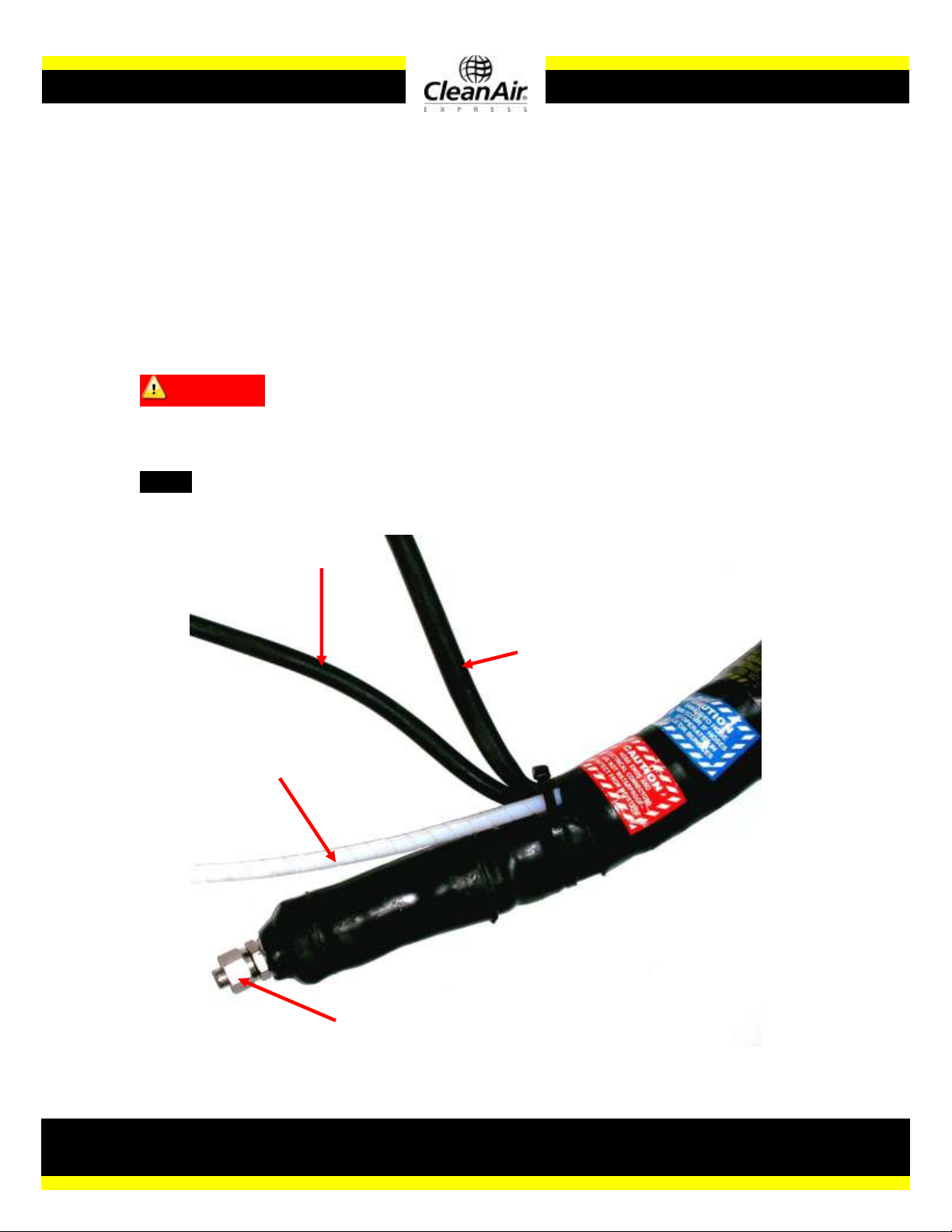
2.3 System Operation
See below for pictures.
Insert one of the thermocouples (3, Figure 1)into the corresponding input on the
temperature controller; the second is simply a spare. It is unnecessary to plug
the second thermocouple into anything. Connect the calibration gas line (2) and
the sample line (1). Plug in the temperature controller and the heated sample
line (4), as well as any other equipment (120V). Select the desired temperature.
Allow 10-15 minutes for the system to warm up then begin sampling.
CAUTION!! –If the light on the temperature controller does not blink when it
gets near the target temperature, overheating is very likely! The most likely
cause is a bad relay in the temperature controller.
NOTE –In the event of an overload, the circuit breaker on the temperature
controlling device will pop out. Simply push it in to reset.
(4) Power
Cord
(3)
Thermocouple
Wire
(2) Calibration
Gas Line
(1) Sample
Line
Connection
Figure 3

Maintenance
Heated Sample Line
7
3 Maintenance and Inspection
CAUTION!! –Do NOT disassemble this product! For internal maintenance
contact Clean Air Express.
3.1 External maintenance
If dirty, the outside of the lines can be cleaned with mild soap. Thermocouple
plugs can also be damaged relatively easily, but are simple to replace. Order
part number 0316M from Clean Air Express.
3.2 Maintenance Issues
For any other maintenance issues, concerns, or questions, please contact
Clean Air Express at (800)-223-3977. Clean Air Express can also be reached by
mail at 212 N. Woodwork Lane Palatine, IL 60067; by fax at (847)-991-8924 or
on the web at http://www.cleanair.com/equipment/Express/main.html

Troubleshooting
Heated Sample Line
8
4 Troubleshooting
Heated Sample Line Controller not heating the sample lines
There is no easy way to repair/replace a burned-out probe heater or
heated sample line in the field. However, often the source of failure is not
a burned-out heater, but a bad connector. Check the connectors for a
broken or bent pin, and repair/replace as necessary. If the connectors
and pins are fine, check to make sure the breaker is not tripped. Reset
the breaker if it has tripped. If resetting the breaker fails, or immediately
trips again, unplug the assembly and look for shorts in the circuit. Do NOT
disassemble the controller; contact Clean Air Express for maintenance.
Overheating
The overheating of this product or the assembly it is contained in is most
often a result of either a thermocouple or temperature controller problem.
If a thermocouple’s insulation is compromised and the bare wires allowed
to come in contact with a surface, it will report the temperature at that
point, rather than at its tip. This can fool at temperature controller into
keeping a heater on continuously. Try using the spare thermocouple
instead. If none of the thermocouples has failed, it means that the
temperature controller itself has failed and needs to be replaced. This
could be due to disengagement of the temperature sensor, a locked
switch, or a bad relay.

Cross Sectional View
Heated Sample Line
9
Electrical
(Thermo-
couples,
Power
cord)
Sample
Line
Calibra-
tion
Line

Parts List
Heated Sample Line
10
CLEAN AIR ENGINEERING
PARTS LIST
HEATED SAMPLE LINE
May 22, 2008
Parent Part #: 0723-* Type: F
*dependent on length
COMPONENT DESCRIPTION QTY UM TYPE
------------------- --------------------- ------- ----- --------
0723G HEATED SAMPLE LINE GUARD 2.0 EA R
SAFETY YELLOW
9801100 HEATED SAMPLE LINE 100' 1.0 EA R
0419SRU UNION 3/8"T-1/4"T S.S. 2.0 EA R
0316M STD MALE THERMOCOUPLE PLUG 2.0 EA R
TYPE K
94032 3 PIN CABLE CLAMP 1.0 EA R
94031 3 PIN AMPHENOL MALE INSERT 1.0 EA R
9403 3 PIN CABLE PLUG 1.0 EA R
(SHELL ONLY)

Our Guarantee
Heated Sample Line
11
Our Guarantee
Clean Air Engineering warrants products to be free from defects and
workmanship for a period of one year after delivery date. The sole and exclusive
remedy for defective goods shall be repair or replacement of defective parts or
payment price of the goods for which damages are claimed, at Clean Air
Engineering’s option.
© Clean Air Engineering –June 2008
This manual suits for next models
4
Table of contents


