CLEAR DESIGN BLADE BPDH18-4 Installation guide

BLADE POWER & DATA
DETAIL DOCUMENT
The images in this document are not to scale.
*

TABLE OF CONTENTS
KEY CONCEPTS................................................................4
IMPORTANT NOTES.........................................................6
ELECTRICAL SPECIFICATIONS........................................7
COMPONENTS..................................................................8
BPDH18-4..........................................................................11
BPDH60............................................................................12
BPDH60-8........................................................................13
POWER/DATA ASSEMBLY..............................................14
INFEED.............................................................................16
POWER POLE..................................................................18
VERTEBRAE...................................................................20
J-CHANNEL & J-CLIPS..................................................21
DESKTOP UNITS.............................................................22
For installation questions call 210.648.2095 or email customerservice@mycleardesign.com
2 3

Attach the Duplexes in a Counterclockwise Direction
START at the front-left position.
Continue in a counterclockwise direction.
Start in the same position on the next harness in line,
and continue with the sequence.
KEY CONCEPTS
3
1
2
4
BPDR_C1
BPDR_C2
BPDR_C3
BPDR_T24_C4
SENSOR ACTIVATED
CONTROL CIRCUIT
If you are installing this power system within the state of California,
you must comply with the California Title 24 regulations.
1
The duplex recepticals are designated as circuit 1, 2, 3, or 4.
The number is printed on each duplex.
Circuit 4 is the sensor activated control circuit.
2
Every duplex, harness, jumper, and infeed displays a North arrow.
The North arrows MUST point the same direction on all parts.
3
Title 24 Electrical Requirement:
HALF of the Duplexes on Each Harness Must be C4 Control Circuits
The duplexes must be attached to the harness in a specific order.
Arrange the duplexes in the correct order by following the sequence.
4
DUPLEX RECEPTICALS
TITLE 24 COMPLIANCE
NORTH
DUPLEX SEQUENCE
C1 C2 C3 C4
REPEAT
STANDARD SEQUENCE
C1 C2 C3C4C4 C4 REPEAT
TITLE 24 SEQUENCE
*
START START
1st Harness Jumper 2nd Harness
For installation questions call 210.648.2095 or email customerservice@mycleardesign.com
4 5

WARNING
Risk of fire or electric shock.
Do not electrically connect
a distribution harness to
more than one supply source.
Disconnect power before servicing.
Failure to do so may cause
shock and/or personal injury.
IMPORTANT NOTES
Connections to the building wiring must
be done by a qualified electrician according
to national, state, and local codes.
Never connect components while system is
under load.
All unused outlets must be capped.
*
*
*
ELECTRICAL SPECIFICATIONS
For installation questions call 210.648.2095 or email customerservice@mycleardesign.com
6 7

COMPONENTS
BPDR_(X)
BP4PFP
BPDH60
BPJCB
BPJ(##)
BPIF(##)
Duplex Receptical
2 Power Outlets Each
Will be Labeled 1, 2, 3, or 4
36" Power Harness
Distributes Power to 8 Outlets
Four-Way Jumper Block
Joins up to 4 Jumpers
Directs Power in Multiple Directions Data Faceplate
4 Data Ports
Snaps into Harness Riser
Power Jumper
Joins Power Harnesses
to Distribute Power Supply
Power Infeed
Connects to Power Source
Introduces Power to the System
BPDH60-8 36" Power Harness
Distributes Power to 16 Outlets
BPDH18-4 18" Power Harness
Distributes Power to 8 Outlets
BSMCTB Leg Mount Bracket
Hanger Kit For Mounting
Cable Tray to Legs
BSMCTB-120 Surface Mount Bracket
Hanger Kit for Mounting
to Underside of Surface
BTEC PR1 Push-In Rivet
Secures Harness onto
the Harness Risers
BCTX Wide Cable Tray
Use with Facing Workstations
Longer than 48"
BNCT Narrow Cable Tray
Use with Side by Side Workstations
and 48" Wide Surfaces
BCTX-RK Wide Harness Riser
Use with Wide Cable Tray.
Holds Power/Data Components
BNCT-RK Narrow Harness Riser
Use with Narrow Cable Tray
Holds Power/Data Components
Cable Tray End Cap
Caps the End of a Cable Tray
to Hide Power/Data Components
For installation questions call 210.648.2095 or email customerservice@mycleardesign.com
BPPCB
Two-Way Jumper Block
Joins 2 Jumpers Together
Use to Make Alternate Jumper Lengths
ELECTRICAL CABLE TRAYS
B120CTB 120 Cable Tray Bracket
Converts Cable Tray For Use
with 120 Degree Stations
KIT-NYC
NYC Infeed Kit
Connects to Power Source
NYC Electrical Code Compliant
8 9

Oval Cable Vertebra
Guides Cables from the
Floor to the Cable Tray
BPDH18-4 18 INCH POWER HARNESS
RECEIVES 4 DUPLEXES
C1 C2
C3
C4
C1 C2
C3
C4
1st Harness Jumper 2nd Harness
C1 C2 C3 C4 REPEAT
STANDARD SEQUENCE
C1 C2 C3C4C4 C4
REPEAT
TITLE 24 SEQUENCE
C1
C2
C3
C4
C1
C4
1st Harness Jumper 2nd Harness
ATTACH THE DUPLEXES IN THE CORRECT ORDER BY FOLLOWING THE SEQUENCE
*
START START
START
START
C4
C4
COMPONENTS CONT.
x 4
x 4
BPP2 Power Pole
Guides Power Infeed from
the Ceiling to the Beam
x 8
VB1 Cable Vertebrae
Guides Cables from the
Floor to the Cable Tray
BPMA
Desktop Power Unit
2 Power Outlets
Clamp to the Surface Edge or
to the Grommet Hole
BPJ47
J-Channel
Mount to Surface for
Wire Management
OPTIONAL ACCESSORIES
BPPCTP
Power Pole Trim Plate
Trims the Opening Where the
Power Pole Enters the Ceiling
BPPBRK
Power Pole Bracket
Used to Anchor the Power Pole
to the Desk Frame
BPDMA
Desktop Data Unit
2 Data Ports
Clamp to the Surface Edge or
to the Grommet Hole
BMFDA
Desktop Combo Unit
2 Power Outlets + 2 Data Ports
Clamp to the Surface Edge or
to the Grommet Hole
For installation questions call 210.648.2095 or email customerservice@mycleardesign.com
VB3
KIT-JC
J-Clip
Mount to Surface for
Wire Management
10 11

BPDH60 36 INCH POWER HARNESS
RECEIVES 4 DUPLEXES
C1 C2
C3
C4
C1 C2
C3
C4
1st Harness Jumper 2nd Harness
C1 C2 C3 C4 REPEAT
STANDARD SEQUENCE
C1 C2 C3C4C4 C4
REPEAT
TITLE 24 SEQUENCE
C1
C2
C3
C4
C1
C4 1st Harness Jumper 2nd Harness
ATTACH THE DUPLEXES IN THE CORRECT ORDER BY FOLLOWING THE SEQUENCE
*
START START
START
START
C4
C4
BPDH60-8 36 INCH HIGH CAPACITY POWER HARNESS
RECEIVES 8 DUPLEXES
C1 C2 C3 C4
C1C2C3
C4
1st Harness
Jumper
2nd Harness
C1 C2 C3 C4 REPEAT
STANDARD SEQUENCE
C1 C2 C3C4C4 C4
REPEAT
TITLE 24 SEQUENCE
C1 C2
C3
C4
C1
C4
1st Harness
Jumper
2nd Harness
ATTACH THE DUPLEXES IN THE CORRECT ORDER BY FOLLOWING THE SEQUENCE
*
START START
START
START
C4 C4
C1 C2 C3 C4
C1C2C3
C4
C2 C4 C3 C4
C1
C4
C2C4
For installation questions call 210.648.2095 or email customerservice@mycleardesign.com
12 13

POWER /DATA ASSEM BLY
For installation questions call 210.648.2095 or email customerservice@mycleardesign.com
Mount Power Harness to Risers
Align power harness C-bracket holes with riser holes.
Insert plastic push rivets through the hole sets.
Insert Duplexes
Slide and snap the duplexes onto the harness.
1
2
PRESS
EXPANDS
Insert Data Faceplates
Data faceplates snap into the riser cutout.
Position the risers so that the faceplates are turned in opposite directions.
3
Place Power/Data Assembly in Cable Tray
Slide risers into cable tray from the end.
The shape of the risers interlocks with the shape of the trays.
4
Attach Cable Tray Hangers
Bolt a hanger to both ends of the cable tray.
These hangers will mount to a BLADE workstation.
5
14 15

A POWER POLE CAN BE USED TO GUIDE THE
INFEED FROM THE CEILING TO THE CABLE TRAY
INFEED LOCATION TYPES
A. Ceiling Infeed
B. Wall Infeed
C. Floor Infeed
PASS THE INFEED DIRECTLY FROM THE WALL
INTO THE CABLE TRAY
A VERTEBRAE CAN BE USED TO GUIDE THE
INFEED FROM THE FLOOR TO THE CABLE TRAY
For installation questions call 210.648.2095 or email customerservice@mycleardesign.com
INFEED
A
C
B
16 17

POWER POLE
#1 Insert Connecting Plates
Lower the connecting plate into the
bottom half of the power pole,
#2 Bolt on Connecting Plates
Tighten 4 bolts to secure the plates.
Align the top half of the power pole.
#3 Bolt on Top Half
Slide top half of the power pole onto
the exposed plates and insert 4 bolts.
Power Pole
Join the top and bottom halves with
2 connecting plates and 8 bolts.
Bottom Half
Top Half
#1 Mount Power Pole Bracket
Insert 4 screws to secure the bracket box.
Attach to an end leg whenever possible.
#2 Position Power Pole
Slide bracket collar around the power pole.
Push the bracket halves together.
#3 Secure the Bracket
Attach the bracket halves with 4 bolts.
The power pole will be clamped in place.
Bracket Box
Bracket Collar
BPPBRK Power Pole Bracket
2 part bracket with 4 bolts
and 4 tapping screws.
#1 Insert Trim Plate
Cut a hole in the appropriate ceiling tile.
Insert trim plate, tabs first into the hole.
#2 Secure Trim Plate
Press on each tab to bend them down.
The tabs will grip the ceiling tile.
#3 Insert Power Pole
Slide power pole into the opening.
The trim plate provides a finished look.
Trim Plate
BPP2
BPPCTP
Power Pole Ceiling Trim Plate
Ceiling tile attachment with
bendable tabs
For installation questions call 210.648.2095 or email customerservice@mycleardesign.com
8
1
7"
16
3
7"
x
18 19

VERTEBRAE
#1 Assemble Vertebrae Links
Insert the pegs of one link into the holes of the next link.
#2 Attach Vertebrae to Surface
Insert 4 wood screws through the top bracket and into the underside of the surface.
For installation questions call 210.648.2095 or email customerservice@mycleardesign.com
J-CHANNEL & J-CLIP
#1 Remove Adhesive Tape Backing
Stick the J-channel or J-clip to a clean dry surface.
#2 Insert Wood Screws
If applicable, insert wood screw(s) to secure the J-channel or J-clip to the underside of a worksurface.
20 21
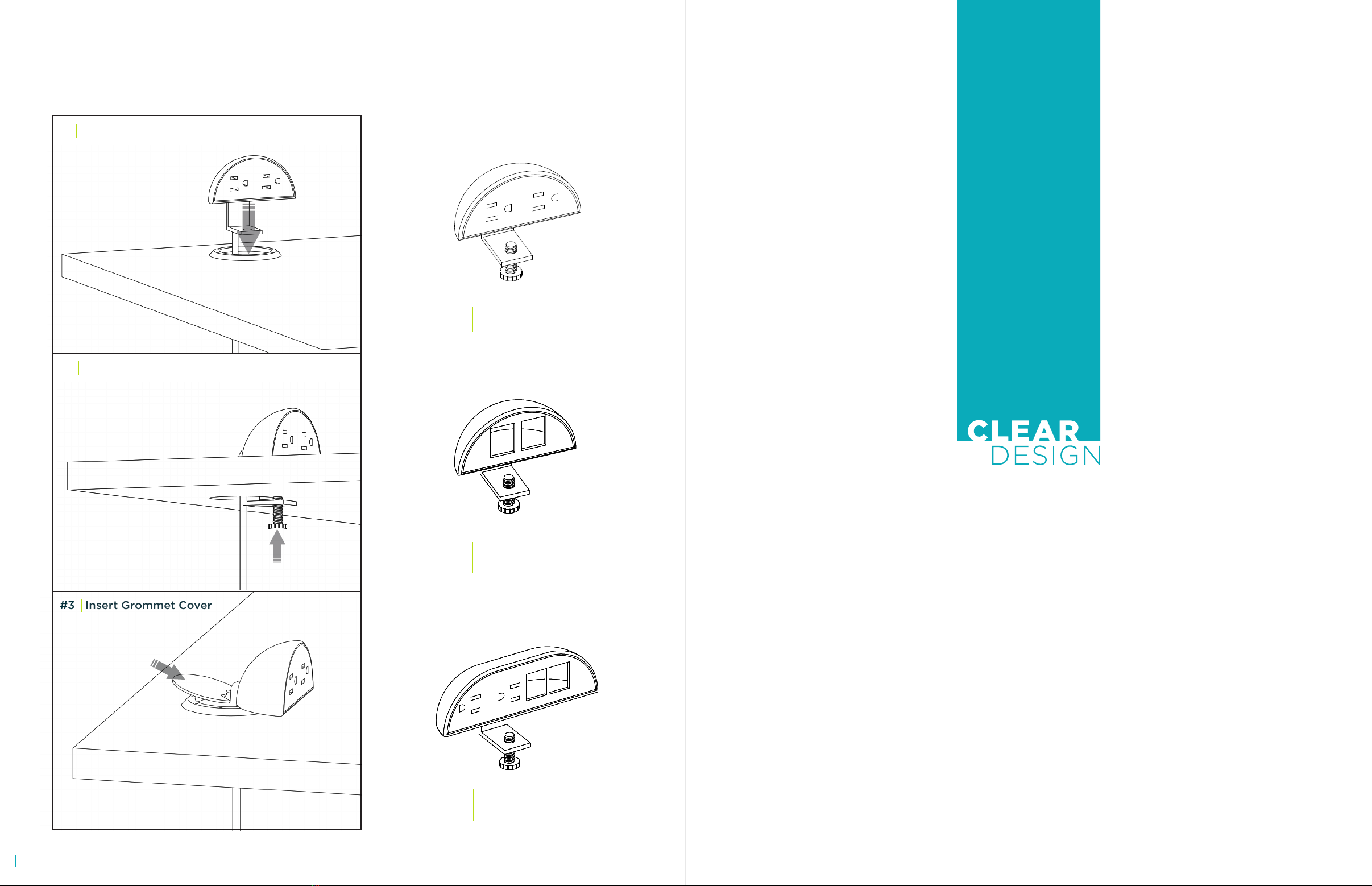
DESKTOP UNITS
Lower into Grommet Hole
Tighten the Bolt
Insert Grommet Cover
#1
#2
#3
BPMA Desktop Power Unit
2 Power Outlets
BPDMA Desktop Data Unit
2 Data Ports
BMFDA Desktop Combo Unit
2 Power Outlets + 2 Data Ports
NOTE: This unit must be edge mounted.
See space differently.
210.648.2095 | mycleardesign.com
© 2017 Clear Design. All rights reserved.
22
This manual suits for next models
2
Table of contents
Popular Power Distribution Unit manuals by other brands


Siemens
Siemens 5SD7 581-2 operating instructions

NetPing
NetPing 8/PWR-220 v4/SMS user guide

Parker
Parker C3Manager-Compax3H manual

DRIESCHER-WEGBERG
DRIESCHER-WEGBERG KSP2132 Operation – and Assembly Instruction

Transtector
Transtector AC Edge 240 installation manual

Siemens
Siemens SIMOSEC operating instructions


