CleaverBrooks Prometha User manual

750-441
01/2020
PromethaTM
Connected Boiler Room Solution
Installation Manual

TO: OWNERS, INSTALLERS, OPERATORS, and SERVICE PERSONNEL
Cleaver-Brooks equipment is designed and engineered to give long life and excellent service on the job. The electrical
and mechanical devices supplied were chosen because of their known ability to perform; however, proper operating tech-
niques and maintenance procedures must be followed at all times.
The operation of this equipment by the owner and any operating personnel must comply with all requirements or regu-
lations of the insurance company and/or other authority having jurisdiction. In the event of any conflict or inconsistency
between such requirements and the warnings or instructions contained herein, please contact Cleaver-Brooks before pro-
ceeding.
WARNING
!
Installation and service must be performed by a qualified service technician. Read
instructions before installing and operating. Keep instructions in a safe place.
Disconnect electrical power before beginning installation. Follow all required site-spe-
cific lockout/tagout procedures.
Installation and application must adhere to local codes established by the authorities
having jurisdiction.

CONTENTS
Hardware Required . . . . . . . . . . . . . . . . . . . . . . . . . . . . . . . . . . . . . . . . . . . . . . . . . . . . . . .1
Tools Required . . . . . . . . . . . . . . . . . . . . . . . . . . . . . . . . . . . . . . . . . . . . . . . . . . . . . . . . . .1
Installation Options . . . . . . . . . . . . . . . . . . . . . . . . . . . . . . . . . . . . . . . . . . . . . . . . . . . . . . .2
Installation Procedure - Hawk Panel, Master Panel, or PT Panel . . . . . . . . . . . . . . . . . . . . . . .3
Power Supply . . . . . . . . . . . . . . . . . . . . . . . . . . . . . . . . . . . . . . . . . . . . . . . . . . . . . .3
Data Transfer Gateway . . . . . . . . . . . . . . . . . . . . . . . . . . . . . . . . . . . . . . . . . . . . . . . .4
12VDC Power Cable . . . . . . . . . . . . . . . . . . . . . . . . . . . . . . . . . . . . . . . . . . . . . . . . .4
LTE Antenna . . . . . . . . . . . . . . . . . . . . . . . . . . . . . . . . . . . . . . . . . . . . . . . . . . . . . . .4
Ethernet Switch . . . . . . . . . . . . . . . . . . . . . . . . . . . . . . . . . . . . . . . . . . . . . . . . . . . . .5
Installation Procedure - DT Panel . . . . . . . . . . . . . . . . . . . . . . . . . . . . . . . . . . . . . . . . . . . . .5
Wiring Diagrams . . . . . . . . . . . . . . . . . . . . . . . . . . . . . . . . . . . . . . . . . . . . . . . . . . . . . . . .6
Ethernet Connections . . . . . . . . . . . . . . . . . . . . . . . . . . . . . . . . . . . . . . . . . . . . . . . . . . . . .8
Troubleshooting . . . . . . . . . . . . . . . . . . . . . . . . . . . . . . . . . . . . . . . . . . . . . . . . . . . . . . . .10
Cellular Connection . . . . . . . . . . . . . . . . . . . . . . . . . . . . . . . . . . . . . . . . . . . . . . . . .10
Hawk Connection . . . . . . . . . . . . . . . . . . . . . . . . . . . . . . . . . . . . . . . . . . . . . . . . . . .11
C-B Cloud Connection . . . . . . . . . . . . . . . . . . . . . . . . . . . . . . . . . . . . . . . . . . . . . . .12
Parts List . . . . . . . . . . . . . . . . . . . . . . . . . . . . . . . . . . . . . . . . . . . . . . . . . . . . . . . . . . . . .13
Tag Lists . . . . . . . . . . . . . . . . . . . . . . . . . . . . . . . . . . . . . . . . . . . . . . . . . . . . . . . . . . . . .14
Hawk ICS . . . . . . . . . . . . . . . . . . . . . . . . . . . . . . . . . . . . . . . . . . . . . . . . . . . . . . . .14
Hawk 1000 . . . . . . . . . . . . . . . . . . . . . . . . . . . . . . . . . . . . . . . . . . . . . . . . . . . . . .17
Hawk 4000 . . . . . . . . . . . . . . . . . . . . . . . . . . . . . . . . . . . . . . . . . . . . . . . . . . . . . .22
Hawk 4000 V2 . . . . . . . . . . . . . . . . . . . . . . . . . . . . . . . . . . . . . . . . . . . . . . . . . . . .27


Prometha™Installation
750-441
1
The Cleaver-Brooks Prometha™ Connected Boiler Solution collects and transmits Hawk and network
data to the C-B cloud to allow customer accessibility via web-based dashboards and optional user
notifications. The specific Hawk network PLCs that are available for this solution are:
• Hawk ICS (PLC must include Ethernet port)
• Hawk 1000
• Hawk 4000
• Hawk 4000 V2
1 - Hardware Required:
Prometha™ requires the addition of four major components to allow data collection from the PLC and
transmission of that data to the cloud via LTE cellular connection.
• Cellular Enable Gateway Device
• Gateway Power Cable
• 12VDC Power Supply
• Antenna
Optional Hardware:
5- or 8-Port Ethernet Switch (optional based on availability of Ethernet ports)
Miscellaneous:
Cables, fuses, cable ties, and DIN rail components - see Parts List.
2 - Tools Required:
Tape measure
Alcohol wipes
Pencil
Drill
7/8” hole saw
Adjustable pliers
Screwdrivers
Diagonal cutter
Electrical Specifications
Voltage: 120VAC, 50-60 Hz
Amps: 1.1A

Prometha™Installation
750-441 2
Wire stripper
Container for drill shavings
Lockout/Tagout kit
Portable monitor (MiniDisplayPort compatible)
Display adapter cable (monitor port to Mini DisplayPort)
Recommended:
Cable tie installation tool
Optional:
RF signal meter (5 band)
Torpedo level (for antenna placement)
Network cable tester
3 - Installation Options:
Each gateway device can accommodate any combination of up to 8 of the compatible systems listed
above. There are several installation location options for the gateway hardware. Regardless of the
option chosen, the installation must ensure that gateway power and Hawk network connections are
maintained as long as any connected boiler is powered up. An optional 5- or 8-port Ethernet switch
will need to be added for systems with no available Ethernet ports.
Single Boiler Installation Options
• Hawk Panel
• PT Panel
• DT Panel w/o Ethernet Switch
Multiple Boiler Installation Options
• Master Panel
• PT Panel
• DT Panel w/ Ethernet Switch
The Hawk Panel option uses the existing Hawk control panel to house the Prometha™ hardware.
The Master Panel and PT (Protocol Translator) Panel options use an existing Master Panel or stand-
alone ProtoNode/CB-PT panel to house the Prometha™ components; the existing Ethernet switch
provides the connection point for each Hawk network device.
The DT (Data Transfer) Panel option incorporates all of the Prometha™ hardware in a single stand-
alone panel and is available with or without an Ethernet switch.
Note: If a site has a weak cellular signal at the Hawk equipment location (as determined during the
pre-installation sales process), the DT Panel can be located up to 328 ft. away from Hawk network.

Prometha™Installation
750-441
3
4 - Installation Procedure - Hawk Panel, Master Panel, or PT Panel
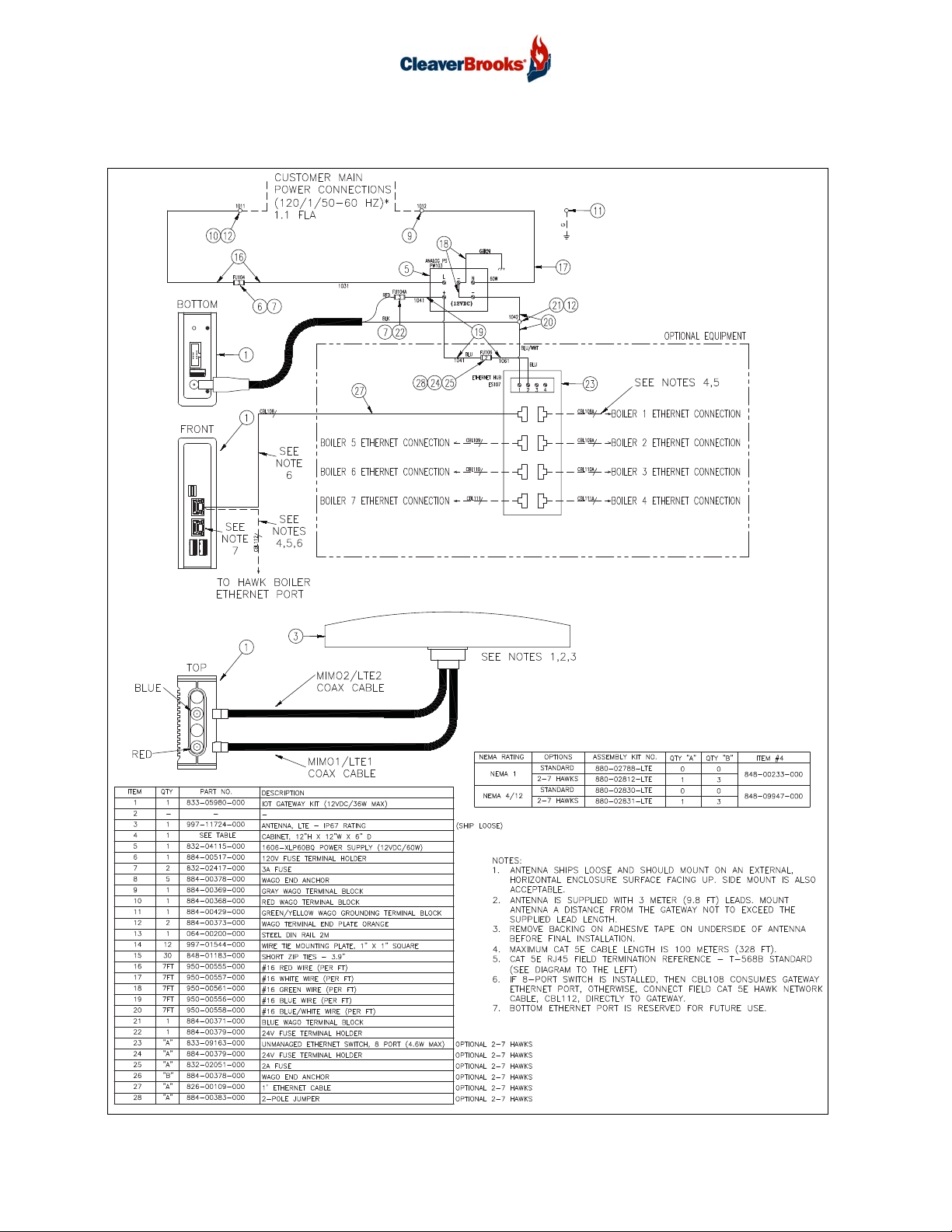
4.1 - Power Supply
Mount the power supply on the DIN rail with the 12VDC output terminal on
top and the 120VAC input terminals on the bottom. See dimensions and
clearances below.
Install the gateway and power supply fuseblocks with 3A fuses and the ter-
minal block with end barrier installed. Install end anchors as needed. The
Supplemental Installation Kit (see Parts List) includes all required fuses and
mounting hardware.
Wire the power supply terminals as described below, referring to the wiring diagram if necessary. All
wiring is 16 gauge (see additional wiring specifications below).
1. Connect a green (ground) wire from the (-) terminal on the top of the power supply to the ground
terminal on the bottom. Insert an additional green wire into the bottom terminal and tighten.
Connect the second wire to an available ground lug or grounded terminal inside the panel.
2. Connect a red wire between the top, load side terminal of the 120V fuse holder and the L (load)
terminal at the bottom of the power supply.
3. Connect a white wire between the N terminal at the bottom of the power supply to the Neutral
terminal strip in the control panel.
4. Use a screwdriver to open the port directly above the terminal on the 120V fuse holder. Connect
a red wire to the bottom, line side terminal. Terminate the other end at a 120VAC power source
in the control panel.
5. Connect a blue wire to either of the two (+) terminals at the top of the power supply and termi-
nate the other end at the bottom, line side terminal of the 24V fuse holder.
6. Connect a blue-and-white wire to either of the two (-) terminals located on the top of the power
supply and connect the other end to the bottom terminal of the blue terminal block.
POWER SUPPLY DIMENSIONS 1.75"W x 3"H x 3.6"D
INSTALLATION CLEARANCES No minimum side clearance (5/8" each side if adjacent device is a heat source).
1.5" top
.75" bottom
TEMPERATURE RANGE 14degF to 158degF
FUSING 3A input fuse for isolation purposes
WIRING SPECIFICATIONS 16AWG Stranded Wire
~1/4" Stripping Length
9 lb.in Tightening Torque
OUTPUT 12VDC
INPUT 120VAC
POWER SUPPLY
WARNING
!
Disconnect power and follow all applicable
lockout/tagout procedures before beginning
installation.

Prometha™Installation
750-441 4
4.2 - Data Transfer Gateway
Mount the gateway on the DIN rail with the coaxial antenna connectors at the
top and the power supply connection at the bottom.
4.3 - 12VDC Power Cable
Insert the plug end into the power supply connection at the bottom of the Gateway. Connect the red
wire to the top, load side terminal of the 24V fuse holder. Connect the black wire to the top terminal
of the blue terminal block.
4.4 - LTE Antenna
The antenna should be mounted on the top, horizontal exterior surface of a Hawk panel, master
panel, DT panel or PT panel. If necessary, mounting the antenna on the side, vertical exterior surface
of these enclosures is an option as well. When choosing a mounting location, maintain as much
clearance as possible from external obstructions. The distance between the gateway and the antenna
cannot exceed 9.8 ft (3 meters), the length of the antenna leads. To install:
1. Use a 7/8” hole saw to drill a hole through the panel for the antenna cable outlet. Collect the drill
shavings in a container for later disposal. Take care not to allow drill shavings to fall inside the
panel.
2. Prepare the panel surface by wiping the installation area clean with an alcohol wipe.
3. Pass the antenna leads through the hole and remove the backing from the adhesive tape on the
underside of the antenna.
4. Attach antenna to the panel.
5. Attach the washer and nut to the threaded mounting stud. Recommended torque for mounting is
21.7 ft·lb (29.4 N·m), not to exceed 28.9 ft·lb (39.2 N·m).
The antenna cables should be routed away from 120VAC wiring wherever possible. Attach cable
MIMO2/LTE2 to the BLUE Gateway coaxial connector and MIMO1/LTE1 to the RED connector. Bun-
dle and tie excess cable lengths and attach to the panel with adhesive tie mounts.
INPUT VOLTAGE 12VDC
GATEWAY DIMENSIONS 1.3"W x 4.6"H x 3.3"D
INSTALLATION CLEARANCES 2" fin side clearance
TEMPERATURE RANGE 32degF to 122degF
ANTENNA DIMENSIONS 8.5"L x 3.7"W x 1.2"H
TEMPERATURE RANGE -40degF to 185degF
INGRESS PROTECTION IP67
GATEWAY

Prometha™Installation
750-441
5
4.5 - Ethernet Switch
An Ethernet switch is required for installations where the PLC Ethernet port is already in use. The
880-10069-000 kit includes the necessary installation hardware:
• Fuse holder
• 2A fuse
• End anchors
• 2-pole jumper
• Ethernet cables
To install:
1. Install Ethernet switch (5-port or 8-port) on the DIN rail.
2. Install 24V fuse holder with 2A fuse next to the gateway fuse.
3. Connect the fuses with the 2-pole jumper. The gateway and Ethernet switch will both use the
12VDC power supply.
4. Wire Terminal 1 of the Ethernet switch to the blue terminal block.
5. Wire Terminal 2 of the Ethernet switch to the 2A fuse.
6. Remove the customer Ethernet connection from the PLC and connect it to any port on the Ether-
net switch.
Using Ethernet cables:
7. Connect the TOP port of the Gateway to any port on the Ethernet switch.
8. Connect the Ethernet switch to the PLC.
5 - Installation Procedure - DT Panel
Subject to the maximum CAT 5E cable length of 328 ft (100 meters), the DT panel can be mounted
in any suitable location with an acceptable cellular signal.
Install the LTE antenna on the panel exterior. The antenna may be mounted on the top or side of the
panel. See steps 1-5 under LTE Antenna above.
Make 120VAC main power wiring connections as described above under Power Supply. Refer to wir-
ing diagram if necessary.
Continue with Ethernet Connections and Troubleshooting below.
WARNING
!
Disconnect power and follow all applicable
lockout/tagout procedures before beginning
installation.

Prometha™Installation
750-441 6
6 - Wiring Diagrams
GATEWAY:
GATEWAY:
GATEWAY:

Prometha™Installation
750-441
7
DT PANEL
12
34
56
78
PWR1
PWR2
1783-US8T
ITEM #s REFER TO WD ABOVE
GRN
12VDC
OPTIONAL
TO GATEWAY
CUSTOMER MAIN POWER CONNECTION
POWER WIRING DETAIL ETHERNET CABLE PIN ASSIGNMENTS

Prometha™Installation
750-441 8
7 - Ethernet Connections
Shown below are the CAT5e cable connections for various installation options.
Single Boiler - Hawk Panel
Single Boiler - PT Panel

Prometha™Installation
750-441
9
Multiple Boilers - DT Panel (with Ethernet switch)
Multiple Boilers - Master Panel
MASTER
PANEL
PLC
PROMETHA
GATEWAY
TM

Prometha™Installation
750-441 10
8 - Troubleshooting
Before powering up the system, connect a portable
monitor to the MiniDisplay port on the Gateway. Con-
nect monitor power to one of the USB ports on the
Gateway.
The Cleaver-Brooks IoT screen provides information on
system status and can serve as a diagnostic tool in
case of connection problems.
8.1 - Cellular Connection
A succesful connection is based on three criteria - Status, Online, and Signal Quality. All three crite-
ria must be positive to pass; if one or more do not pass, the cellular connection has failed.
In the event of a failed connection:
1. Confirm cellular signal is available. Use either:
a. Carrier compatible cell phone to validate signal strength of at least one bar.
b. Signal meter to ensure signal is within -45 to -95 dBm range.
2. Check antenna cables. Ensure:
a. Antenna connections to gateway are threaded tightly.
b. Antenna cables are not damaged, pinched, or kinked.
c. Antenna Cable 1 and Antenna Cable 2 are connected to the correct gateway port.
Mini-DisplayPort
USB

Prometha™Installation
750-441
11
8.2 - Hawk Connection
In the event of a problem with the Hawk control system connection:
• Confirm gateway Ethernet cable is plugged into the top Ethernet port of the gateway.
• Confirm PLC Ethernet cable is plugged into the Hawk PLC or an Ethernet switch on the Hawk network. Do
not plug the Ethernet cable into the 1769-SM2 module in the Hawk PLC I/O rack or, for older Hawks, the
1761-NET-ENI module.
• Confirm the offline Hawk control panel is powered up. Pay close attention to the PLC and Ethernet switch,
if applicable, to ensure they are also powered up in the panel.
• Confirm IP addresses match. The Hawk PLC IP address displayed on the portable monitor must be consis-
tent with IP address displayed on HMI (on the base rail). If mismatched, change the PLC IP address to
match (refer to Hawk O&M manual) or call C-B IoT support at the number listed on the portable monitor
for assistance.
• Confirm there is no gateway IP conflict on the Hawk network. The gateway IP address is listed (2) and
there shouldn’t be any other devices on the network with the same IP address. If there are, unplug the net-
work cable from the gateway device and call C-B IoT support with the preferred gateway IP address for
gateway IP address reassignment.
• Confirm the cables are good: use a network cable tester (Ideal LinkMaster 62-200), to test the Hawk net-
work cabling. A failed test could indicate either a damaged cable or an improperly terminated RJ45 con-
nector. Damaged cables that fail the network cable test will need replacing. Ensure that any incorrectly
terminated RJ45 connectors are reterminated following the T-568B wiring standard. Refer to illustration in
Wiring Diagrams section above for the T-568B pinout diagram.
• Confirm the CAT5e Ethernet cable does not exceed 328 ft in length. Cables beyond this length will not
maintain proper connection.

Prometha™Installation
750-441 12
8.3 - C-B Cloud Connection
In the event of an error message indicating an issue with the C-B cloud connection (2), call C-B Sup-
port and provide Host Name information (1).

Prometha™Installation
750-441
13
9 - Parts List
Prometha™ - Base Hardware
QTY PART NUMBER DESCRIPTION
1 833-05980-000 Gateway
1 997-11724-000 Antenna
1 832-04115-000 Power Supply
1 750-00441-000 O&M Manual
880-10068-000 - Supplemental Prometha™ Installation Kit
QTY PART NUMBER DESCRIPTION
1 826-00111-000 Ethernet Cable, 7'
7 950-00555-000 Red #16 Wire
7 950-00557-000 White #16 Wire
7 950-00561-000 Green #16 Wire
7 950-00556-000 Blue #16 Wire
7 950-00558-000 Blue/White #16 Wire
2 832-02417-000 3 amp Fuse
1 884-00379-000 Fuse Holder, 24V
1 884-00517-000 Fuse Holder, 120V
1 884-00371-000 Blue Terminal Block
1 884-00373-000 End Plate
7 884-00378-000 Din Rail End Anchors
30 848-01183-000 Cable Ties
12 997-01544-000 Adhesive Tie Mounts
Prometha™ - Optional Ethernet Switches
QTY PART NUMBER DESCRIPTION
1 833-09181-000 Ethernet Switch, 5-port
1 833-09163-000 Ethernet Switch, 8-port
880-10069-000 - Optional 5 or 8 Port Ethernet Switch Install Kit
QTY PART NUMBER DESCRIPTION
1 884-00379-000 Fuse Holder, 24V
3 884-00378-000 Din Rail End Anchors
1 832-02051-000 2 amp Fuse
1 884-00383-000 2-Pole Jumper
1 826-00109-000 Ethernet Cable, 1'
1 826-00350-000 Ethernet Cable, 4'

Prometha™Installation
750-441 14
10 - Tag Lists
Read-only tags for Prometha™ compatible devices
Hawk ICS
Point Name Data Type
1 Drive Fault BI
2 Modbus Com Error BI
3 Low Water BI
4 BC Alarm BI
5 Boiler Limits Open BI
6 High Stack Temp Alarm BI
7 High Stack Temp SD BI
8 External Interlock BI
9 I/O module fault BI
10 Steam Sensor Fail BI
11 Air Drive out of Position Alarm BI
12 Gas Drive out of Position Alarm BI
13 F/A Ratio Controller Fault BI
14 No Fuel Selected BI
15 Low Clogix Battery BI
16 Non Recycle Limit Relay Fail BI
17 Recyle Limit Relay Fail BI
18 Remote Modulation Signal Fail BI
19 Header Sensor Fail BI
20 TC Channel Fail BI
21 Low O2 Alarm BI
22 High Limit Alarm BI
23 ALWCO BI
24 Low Gas Pressure/Low Oil Temp BI
25 High Gas Pressure/High Oil Temp BI
26 Low Oil Pressure BI
27 High Oil Pressure BI
28 Oil Drawer Switch Not Made BI
29 Low Atomizing Air Pressure BI
30 Low Combustion Air Pressure BI
31 AUX Alarm 1 BI
32 AUX Alarm 2 BI
33 Blower On BI
34 Purge Input BI
35 Release To modulate Input BI
36 Low Fire Switch BI
37 High Fire Switch BI
38 Ready to start/Limits Closed BI
39 External Start Interlock BI
40 ALFCO BI
41 Pilot BI
42 Main Fuel Valve Open BI
43 Fuel 1 Selected BI
44 Fuel 2 Selected BI

Prometha™Installation
750-441
15
45 FSG Alarm BI
46 LWCO Shutdown BI
47 Remote enable input BI
48 Burner Switch BI
49 Recycle Limit Relay BI
50 External Device Start BI
51 Non Recycle Limit Relay BI
52 Drive to Low Fire (FARC) BI
53 Start Slave Blr (2 Blr LL) BI
54 Load Demand Output BI
55 Alarm Output BI
56 Boiler Ready (LL) BI
57 Boiler Load Demand BI
58 Firing Rate Remote/Llag BI
59 Firing Rate Manual BI
60 Firing Rate Auto BI
61 Hot Stand By BI
62 Warm Up BI
63 Fuel 3 Selected BI
64 Aux Alarm 3 BI
65 Steam or Hot Water BI
66 Level Master Present BI
67 Variable Speed Drive Present BI
68 Economizer Present BI
69 Combustion Air Temp Present BI
70 Oil Temp Sensor Present BI
71 O2 Analyzer Present BI
72 Feedwater or Return Temp Present BI
73 Outdoor Reset Selected BI
74 Parallel Positioning Selected BI
75 Two boiler lead lag master select BI
76 Two boiler lead lag slave select BI
77 Master panel select BI
78 Hot stand by select BI
79 Dual setpoint select BI
80 Gas Flow Select BI
81 Oil Flow Select BI
82 Steam Flow Select BI
83 Water Flow Select BI
84 Honeywell or Fireye BI
85 High Water Alarm BI
86 Oil Drive out of Position Alarm BI
87 FGR Drive out of Position Alarm BI
88 Air Actuator FB Alarm Low BI
89 Air Actuator FB Alarm High BI
90 Fuel1 Actuator FB Alarm Low BI
91 Fuel1 Actuator FB Alarm High BI
92 Fuel2 Actuator FB Alarm Low BI
93 Fuel2 Actuator FB Alarm High BI
94 FGR Actuator FB Alarm Low BI
95 FGR Actuator FB Alarm High BI
Hawk ICS (continued)

Prometha™Installation
750-441 16
96 VSD Deviation Alarm BI
97 Flame Strength Honeywell AI
98 Combustion Air Fan Speed AI
99 Blower Motor Kw AI
100 Boiler Efficiency AI
101 Firing Rate AI
102 O2 Level AI
103 Set Point Steam Pressure/Water Temp AI
104 Water Level AI
105 Steam Pressure or HW Temp AI
106 Combustion Air Pressure AI
107 Stack Temp Before Econ AI
108 Combustion Air Temp AI
109 Water Temp Shell/Outdoor Temp AI
110 Feedwater Temp/Econ Water Out Temp AI
111 Stack Temp After Econ/Return HW AI
112 Economizer Water In Temp AI
113 Analog Input User Defined #1 Input AI
114 Analog Input User Defined #2 Input AI
115 Analog Input User Defined #3 Input AI
116 Analog Input User Defined #4 Input AI
117 Safety Valve Setting or Max Water Temp AI
118 Header Pressure or temp 2 Boiler LL AI
119 Set Point 2 Boiler LL AI
120 Boiler Off Point AI
121 Boiler On Point AI
122 AR[25] Future AI
123 AR[26] Future AI
124 Brnr Control Status Line 1 Honeywell AI
125 Brnr Control Status Line 2 Honeywell AI
126 Brnr Control Status Line 1 Fireye AI
127 Brnr Control Status Line 2 Fireye AI
128 Flame Signal Fireye AI
129 Fuel 1 Type AI
130 Fuel 2 Type AI
131 Fuel 3 Type AI
132 Boiler ID AI
133 Elapsed Time (First 16 Bits) AI
134 Elapsed Time (Second 16 Bits) AI
135 Number Of Cycles (First 16 Bits) AI
136 Number Of Cycles (Second 16 Bits) AI
137 AI[13] Future AI
138 AI[14] Future AI
139 Elapsed Time AI
140 Number Of Cycles AI
Hawk ICS (continued)
Table of contents
Other CleaverBrooks Boiler Supplies manuals