CleaverBrooks ADAC 1000 User manual

750-386
05/2017
ADAC 1000
Deaerator Control
Operation Manual

DO NOT OPERATE, SERVICE, OR REPAIR THIS EQUIPMENT UNLESS YOU FULLY UNDERSTAND
ALL APPLICABLE SECTIONS OF THIS MANUAL.
DO NOT ALLOW OTHERS TO OPERATE, SERVICE, OR REPAIR THIS EQUIPMENT UNLESS THEY
FULLY UNDERSTAND ALL APPLICABLE SECTIONS OF THIS MANUAL. FAILURE TO FOLLOW ALL
APPLICABLE WARNINGS AND INSTRUCTIONS MAY RESULT IN SEVERE PERSONAL INJURY OR
DEATH.
TO: Owners, Operators and/or Maintenance Personnel
This operating manual presents information that will help to properly operate and care for the equipment. Study its
contents carefully. The unit will provide good service and continued operation if proper operating and maintenance
instructions are followed. No attempt should be made to operate the unit until the principles of operation and all
of the components are thoroughly understood. Failure to follow all applicable instructions and warnings may result
in severe personal injury or death.
It is the responsibility of the owner to provide safety training not only to his or her personnel, but to any
contractor’s personnel who are servicing, repairing or operating the equipment.
Cleaver-Brooks equipment is designed and engineered to give long life and excellent service on the job. The
electrical and mechanical devices supplied as part of the unit were chosen because of their known ability to
perform; however, proper operating techniques and maintenance procedures must be followed at all times.
Although these components afford a high degree of protection and safety, operation of equipment is not to be
considered free from all dangers and hazards inherent in operating and maintaining this equipment.
Such “automatic” features as may be included in the design should not be understood as relieving the attendant of
responsibilities. Such features merely take over certain repetitive chores, allowing more time for the proper upkeep
of equipment.
It is solely the operator’s responsibility to properly operate and maintain the equipment. No amount of written
instructions can replace intelligent thinking and reasoning and this manual is not intended to relieve the operating
personnel of the responsibility for proper operation. On the other hand, a thorough understanding of this manual is
required before attempting to operate, maintain, service, or repair this equipment.
Operating controls will normally function for long periods of time and we have found that some operators become
lax in their daily or monthly testing, assuming that normal operation will continue indefinitely. Malfunctions of
controls lead to uneconomical operation and damage to the equipment. In most cases, these malfunctions can be
traced directly to carelessness and deficiencies in testing and maintenance.
The operation of this equipment by the owner and the operating personnel must comply with all requirements or
regulations of their insurance company and/or other authority having jurisdiction. In the event of any conflict or
inconsistency between such requirements and the warnings or instructions contained herein, please contact
Cleaver-Brooks before proceeding.

CONTENTS
Chapter 1 - General
Introduction . . . . . . . . . . . . . . . . . . . . . . . . . . . . . . . . . . . . . . . . . . 1-2
Single Tank System Description . . . . . . . . . . . . . . . . . . . . . . . . . . . . 1-2
Two Tank System Description . . . . . . . . . . . . . . . . . . . . . . . . . . . . . . 1-4
Specifications . . . . . . . . . . . . . . . . . . . . . . . . . . . . . . . . . . . . . . . . . 1-6
ADAC Software . . . . . . . . . . . . . . . . . . . . . . . . . . . . . . . . . . . . . . . . 1-6
Chapter 2 - System Components
Components . . . . . . . . . . . . . . . . . . . . . . . . . . . . . . . . . . . . . . . . . . . 2-2
Control Panel . . . . . . . . . . . . . . . . . . . . . . . . . . . . . . . . . . . . . . . . . 2-7
Optional Accessories . . . . . . . . . . . . . . . . . . . . . . . . . . . . . . . . . . . . 2-9
Chapter 3 - Commissioning
Main Menu . . . . . . . . . . . . . . . . . . . . . . . . . . . . . . . . . . . . . . . . . . . 3-2
Begin System Configuration . . . . . . . . . . . . . . . . . . . . . . . . . . . . . . . 3-2
System Configuration Screen 1 - Single Tank . . . . . . . . . . . . . . . . . . . 3-4
System Configuration Screen 1 - Dual Tank . . . . . . . . . . . . . . . . . . . . 3-6
System Configuration Screen 2 - Single Tank . . . . . . . . . . . . . . . . . . . 3-7
System Configuration Screen 2 - Dual Tank . . . . . . . . . . . . . . . . . . . . 3-8
Transfer Pumps - Dual Tank Systems . . . . . . . . . . . . . . . . . . . . . . . . 3-9
System Configuration Screen 3 . . . . . . . . . . . . . . . . . . . . . . . . . . . . 3-10
System Configuration Summary . . . . . . . . . . . . . . . . . . . . . . . . . . . . 3-11
Analog Input Configuration . . . . . . . . . . . . . . . . . . . . . . . . . . . . . . . 3-11
Analog Input View . . . . . . . . . . . . . . . . . . . . . . . . . . . . . . . . . . . . . 3-15
Analog Input Trending . . . . . . . . . . . . . . . . . . . . . . . . . . . . . . . . . . 3-15
Pump Configuration . . . . . . . . . . . . . . . . . . . . . . . . . . . . . . . . . . . . 3-16
Pump Control . . . . . . . . . . . . . . . . . . . . . . . . . . . . . . . . . . . . . . . . 3-20
Pump VFD Control . . . . . . . . . . . . . . . . . . . . . . . . . . . . . . . . . . . . 3-25
Primary Makeup Valve Control . . . . . . . . . . . . . . . . . . . . . . . . . . . . 3-29
DA Primary Makeup Valve Bias . . . . . . . . . . . . . . . . . . . . . . . . . . . . 3-31
Secondary Makeup Valve Control . . . . . . . . . . . . . . . . . . . . . . . . . . 3-33
Steam PRV Valve Control . . . . . . . . . . . . . . . . . . . . . . . . . . . . . . . . 3-33
Overflow Valve Control . . . . . . . . . . . . . . . . . . . . . . . . . . . . . . . . . . 3-34
Chemical Feed Control . . . . . . . . . . . . . . . . . . . . . . . . . . . . . . . . . . 3-35
DA Bypass . . . . . . . . . . . . . . . . . . . . . . . . . . . . . . . . . . . . . . . . . . 3-37
Auxiliary Analog Inputs . . . . . . . . . . . . . . . . . . . . . . . . . . . . . . . . . . 3-41
Lead Lag Order by Communications . . . . . . . . . . . . . . . . . . . . . . . . 3-43
PLC Ethernet Configuration . . . . . . . . . . . . . . . . . . . . . . . . . . . . . . . 3-44
Text/Email . . . . . . . . . . . . . . . . . . . . . . . . . . . . . . . . . . . . . . . . . . 3-46
PLC Input/Output Status . . . . . . . . . . . . . . . . . . . . . . . . . . . . . . . . 3-47
Update Date/Time . . . . . . . . . . . . . . . . . . . . . . . . . . . . . . . . . . . . . 3-47
Contact Information . . . . . . . . . . . . . . . . . . . . . . . . . . . . . . . . . . . . 3-48
System Information . . . . . . . . . . . . . . . . . . . . . . . . . . . . . . . . . . . . 3-49
Display Configuration . . . . . . . . . . . . . . . . . . . . . . . . . . . . . . . . . . . 3-50

Chapter 4 - Operation
System Monitoring and Operation . . . . . . . . . . . . . . . . . . . . . . . . . . . 4-2
Remote Monitoring . . . . . . . . . . . . . . . . . . . . . . . . . . . . . . . . . . . . . . 4-6
Alarms . . . . . . . . . . . . . . . . . . . . . . . . . . . . . . . . . . . . . . . . . . . . . . 4-6
Troubleshooting . . . . . . . . . . . . . . . . . . . . . . . . . . . . . . . . . . . . . . . 4-8
PLC Status . . . . . . . . . . . . . . . . . . . . . . . . . . . . . . . . . . . . . . . . . . 4-11
Chapter 5 - Input/Output Lists
Single Tank PLC I/O Layout . . . . . . . . . . . . . . . . . . . . . . . . . . . . . . . . 5-2
Two Tank PLC I/O Layout . . . . . . . . . . . . . . . . . . . . . . . . . . . . . . . . . 5-4
Chapter 6 - Parts
Part List. . . . . . . . . . . . . . . . . . . . . . . . . . . . . . . . . . . . . . . . . . . . . . 6-2
APPENDIX A - Variable Frequency Drive Parameters
APPENDIX B - ADAC 1000 ProtoNode Tags
APPENDIX C - Loading a PLC Program
APPENDIX D - Deaerator Reference Drawings

www.cleaverbrooks.com
Chapter 1
General
Introduction . . . . . . . . . . . . . . . . . . . . . . . . . . . . . . . . . . . . . . 1-2
Single Tank System Description . . . . . . . . . . . . . . . . . . . . . . . 1-2
Two Tank System Description . . . . . . . . . . . . . . . . . . . . . . . . . 1-4
Specifications . . . . . . . . . . . . . . . . . . . . . . . . . . . . . . . . . . . . . 1-6
ADAC Software . . . . . . . . . . . . . . . . . . . . . . . . . . . . . . . . . . . . 1-6

Chapter 1 — General
1-2 Part No. 750-386
1.1-Introduction
The Cleaver-Brooks ADAC 1000 is an exclusive Deaerator and/or
Surge Tank Management and Control System specifically designed
to integrate the functions of a Programmable Controller with other
operating and ancillary controls. The Programmable Controller
(PLC) is a modular design providing flexibility for expansion with
easily serviceable components. The ADAC 1000 system
incorporates a user-friendly, graphical touch screen Human
Machine Interface that displays tank parameters, fault annunciation
and alarm history, as well as providing access to system
configuration and control functions. The system provides a
complete tank level, tank pressure, and pump control solution.
In addition to installation on new Deaerators and Surge tanks, the
ADAC 1000 can be added as a retrofit to existing tanks. Call your
local authorized Cleaver-Brooks representative for details.
1.2-Single Tank System Description
A single tank system can control up to 5 pumps, all of which can
be run by contactors, combination starters, soft starters, or Variable
Frequency Drives. All pumps on a tank must utilize the same type
of starter/drive.
Pumps on a common header can be alternated on a customer
defined schedule and be set up in a customer defined lead lag
format.
When lead lag operation is in use, a pressure transmitter mounted
in the common header sends a signal to the PLC. The customer sets
the pressure point via the touch screen. If the first pump cannot
achieve that set point, the PLC will start a second pump and so on.
If the pressure rises above the set point, the PLC will shed the last
pump and so on. During normal operation the lead pump will
always run.
Pumps on a “one pump per boiler” installation can be controlled by
a contact closure on the boiler. Variable Frequency Drives cannot be
used in a one pump per boiler configuration where each pump is
hard piped to individual boilers. VFDs are only available on common
pump discharge header configurations.
Standard system is capable of using discrete level alarm switches
(such as the McDonnell Miller 63 or 64) for fixed level alarms, or a
level transmitter which can be configured from the touch screen.
OPC compliant Ethernet IP communications are included as
standard. This feature can be used to connect the ADAC 1000
system to a boiler Master Panel or customer BAS.
1.2.1 - Standard Equipment
The PLC based control system for a single tank includes a base unit
consisting of the processor and embedded I/O, power supply, I/O

Chapter 1 — General
Part No. 750-386 1-3
cards, 7" color touch screen, and NEMA 4 control panel.
Programming and I/O are provided for the following:
• 1-5 pumps using contactors, soft starters or combination starters; inputs
and outputs which include pump Hand-Off-Auto selector switches, a
pump motor running input, and pump run output.
• Low Water pump cut off
• Audible Alarm output
• Stack Light outputs and light (Green for all systems normal, Yellow for
non-critical alarms such as High Water, Red for critical alarm such as
Pump Failure)
• Recirc Bypass output
• Chemical Feed Relay output
• Boiler 1-5 feed water required inputs for one pump per boiler
configuration
• Analog Tank Pressure Input
• Analog Tank Temperature Input
• Analog Tank Level Input
• Analog Discharge Header Pressure Input
• Tank primary and secondary makeup valve control
• Text/email
• Remote setpoint by communications
• Remote Lead Lag pump rotation by communications
• US or metric units
1.2.2 - Options
Programming and I/O cards for the following are optional (each
option requires the preceding ones):
Option 1
• VFD Pump 1-3
• PRV or Overflow Valve
Option 2
• VFD Bypass or 1 Pump per Boiler 1-5
• Tank Discrete Level Switches
Option 3
• VFD Pump 4-5
Option 4
• User Configured Analog Inputs
• Tray Temp/Pressure Analog Inputs for Tray Deaerators
Note: Each ADAC 1000 programming option requires the corresponding
hardware (drives, valves, transmitters, switches, etc.)

Chapter 1 — General
1-4 Part No. 750-386
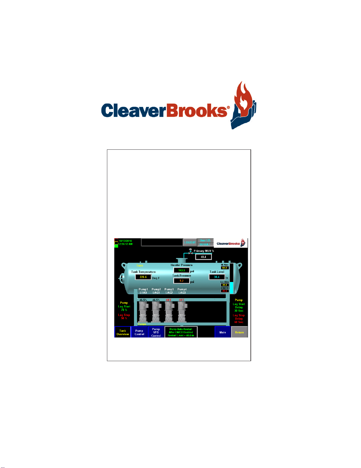
1.3-Two Tank System Description
Two Tank systems can control up to 4 boiler feed pumps and 3
transfer pumps (6 pumps total), all of which can be run by
contactors, combination starters, soft starters, or Variable
Frequency Drives. The pump control method selected must be the
same for all pumps on a tank, but the Tank 1 method can be
different from Tank 2. For example, Tank 1 may use Variable
Frequency Drives, but Tank 2 may use contactors.
Pumps on a common header can be alternated on a customer
defined schedule and be set up in a customer defined lead lag
format.
When lead lag operation is in use, a pressure transmitter mounted
in the common header sends a signal to the PLC. The customer sets
the pressure point via the touch screen. If the first pump cannot
achieve that set point, the PLC will start a second pump and so on.
If the pressure rises above the set point, the PLC will shed the last
pump and so on. During normal operation the lead pump will
always run.
Pumps on a “one pump per boiler” installation can be controlled by
the boiler. Variable Frequency Drives cannot be used in a one pump
per boiler configuration where each pump is hard piped to
individual boilers. VFDs are only available on common pump
discharge header configurations.
Standard system is capable of using discrete level alarm switches
(such as the McDonnell Miller 63 or 64) for fixed level alarms, or a
level transmitter which can be configured from the touch screen.
1.3.1 - Standard Equipment
7 inch color touch screen is standard.
A three module stack light is standard with a light for each mode.
Green for normal, Yellow for non critical alarms Red for critical
alarms. An audible alarm is standard, either a bell, horn or
electronic sounder
PLC based control system for a two tank starts with and includes a
base unit consisting of the processor and embedded I/O, power
supply, I/O cards, 7" color touch screen, and Nema 4 control panel
to provide the following functions
Level control can be an independent mechanical system, or by using
the above mentioned transmitter, control an electrical or I/P make-
up valve.
Tank Pressure is monitored by a transmitter in steam space. PRV
can be an independent mechanical system or an electrical or I/P
pressure reducing valve.
The second tank will be treated as an atmospheric pressure tank
and will not have a tank pressure sensor.

Chapter 1 — General
Part No. 750-386 1-5
Communication options include OPC compliant Ethernet IP to
Boiler master panel or customer BAS.
PLC based control system for a two tank starts with and includes a
base unit consisting of the processor and embedded I/O, power
supply, I/O cards, 7" color touch screen, and NEMA 4 control panel.
Programming and I/O provided for the following:
• 1-3 pumps on the first tank, 1-2 pumps on the second tank using
contactors, soft starters or combination starters; inputs and
outputs which include pump Hand-Off-Auto selector switches, a
pump motor running input, and pump run output.
• Low Water pump cut off on both tanks
• Audible Alarm output
• Stack Light outputs and light (Green for all systems normal, Yellow
for non-critical alarm such as High Water, Red for critical alarms
such as Pump Failure)
• Recirc Bypass output on DA tank only
• Chemical Feed Relay output on both tanks
• Analog Tank Pressure Input on DA tank only
• Analog Tank Temperature Input and transmitter on both tanks
• Analog Tank Level Input on both tanks
• Analog Discharge Header Pressure Input on both tanks using
common headers
• Tray Temperature and Pressure analog inputs for Tray Deaerators -
each uses one customer configured analog input
• 4 customer configured Analog Inputs
• 1-4 Feed Pump Proving Flow Switch Inputs
• Primary makeup valve control on both tanks
1.3.2 - Options
Programming and I/O cards for the following are optional (each
option requires the preceding ones):
Option 1
• DA or Surge Tank Discrete Level Switches
• Feed Pump 4 or Transfer Pump 3
• Transfer Pump Flow/Pressure Switches
• DA Bypass
Option 2
• VFD on feed or transfer pumps
• 2nd MUV
• PRV or Overflow Valve
Option 3
• VFD Bypass or 1 Pump per Boiler 1-4

Chapter 1 — General
1-6 Part No. 750-386
Note: Each ADAC 1000 programming option requires the
corresponding hardware (drives, valves, transmitters, switches,
etc.)
1.4-Specifications
1.5-ADAC Software (standard programs)
Single Tank
PLC - 98500592
HMI 7” - 98500631
10” - 98500630
Dual Tank
PLC - 98500594
HMI 7” - 98500633
10” - 98500632
Power
Power Supply Voltage 120 VAC (102 VAC - 132 VAC)
Power Supply Frequency 50 or 60 Hz
Maximum Total Connected Load 500 VA
Fusing
Controller Power 2A
DC Power Supply 3A
Touch Screen HMI 2A
Environmental
Ambient Operating Temperature Limits 32° to 130°F.
Humidity 85% RH continuous, non-condensing
Vibration Continuous to 0.5 G

www.cleaverbrooks.com
Chapter 2
System Components
Components . . . . . . . . . . . . . . . . . . . . . . . . . . . . . . . . . . . . . . . . . . . 2-2
Control Panel . . . . . . . . . . . . . . . . . . . . . . . . . . . . . . . . . . . . . . . . . 2-7
Optional Accessories . . . . . . . . . . . . . . . . . . . . . . . . . . . . . . . . . . . . 2-9

Chapter 2 — System Components
2-2 Part No. 750-386
2.1-Components
The ADAC control system consists primarily of a Programmable
Controller (PLC), touch screen Human Machine Interface (HMI),
24VDC power supplies, stack light, and various relays. Optional
components could include an EtherNet switch.
The ADAC controller is factory pre-programmed to work with most
Cleaver-Brooks deaerator and surge tank systems, yet allows easy
configuration for specific options. The controller program logic is
password secured, ensuring tamper-proof operation. The touch
screen HMI provides user-friendly access to pump and level control
functions, diagnostics and alarm histories, and any connected
operating parameters.
2.1.1 - Base Unit
The PLC and associated devices are mounted on a DIN rail in the
ADAC control panel.
01234567
8 9 10 11 12 13 14 15
01234567
8910
A0 B0 Z0
A1 B1 Z1
0 2 FUSE
13OK
11 12 13 14 15
HIGH SPEED
COUNTER
INOUT
DC
INPUT
24VDC
SINK\
SOURCE
24VDC
SOURCE
OUTPUT
DC
+24VDC COM FG
01234567
8 9 10 11 12 13 14 15
01234567
8910
A0 B0 Z0
A1 B1 Z1
0 2 FUSE
13OK
11 12 13 14 15
HIGH SPEED
COUNTER
INOUT
DC
INPUT
24VDC
SINK\
SOURCE
24VDC
SOURCE
OUTPUT
DC
+24VDC COM FG
00
01
02
03
04
05
06
07
NC
+V
00
01
02
03
04
05
06
07
COM
0
COM
0
08
09
10
11
12
13
14
15
NC
+V
08
09
10
11
12
13
14
15
COM
1
COM
1
A0+
B0+
Z0+
A1+
B1+
Z1+
+V
OUT
1
OUT
0
COM COM
A0-
B0-
Z0-
A1-
B1-
Z1-
+V
0UT
3
V
in
0+
V
in
2+
V
OUT
0+
I
OUT
0+
V
OUT
1+
I
in
3+
V
in
1+
I
in
1+
I
in
1+
V
in
3+
CJC
-
CJC
+
V/I
in
1-
V/I
in
3-
V/I
in
0-
V/I
in
2-
I
in
0+
I
in
2+
OUT
2
COMCOM
DC IN HSC
DC OUT ANALOG
00:00:BC:2E:69:F6
L24ER
QBFC1B
Controller Embedded
I/O

Chapter 2 — System Components
Part No. 750-386 2-3
The PLC holds the program logic and configuration data for the
ADAC controls. The program logic is password-secured at the
factory. The included power supply powers all of the rack modules
as well as the integrated communications bus.
The remaining control components vary according to the type of
system and the options chosen. The base controller embedded I/O
consists of 16 discrete (digital) inputs, 16 digital outputs, 4 analog
inputs, and 2 analog outputs. A right end cap terminator is required
in order to complete the controller communications bus. It attaches
to the right side of the last module in the rack.
Optional modules can be added to the PLC to provide additional
functionality (see below).
Note: The PLC expects each device to be in a specific slot location. The ADAC
1000 will not function unless all devices are properly installed and configured.
Single Tank PLC Layout (also see Chapter 5, Input/Output Lists)
Base System
1. Processor (Slot 0)
2. Slot 1 - Embedded Digital Inputs - 24VDC
3. Slot 1 - Embedded Digital Outputs - 24VDC
4. Slot 2 - Embedded Analog Inputs
5. Slot 2 - Embedded Analog Outputs
Figure 2-1 Single Tank PLC Layout
DISCRETE and ANALOG Signal Types
Discrete inputs/outputs are used for signals taking on only one of two possible
states (on/off, open/ close, etc.). The input state is represented by a bit (0 or 1) in
the control logic. Example:
Pump Running (yes/no)
Analog signals can assume almost infinite values within the fixed analog input/
output current range of 4-20 mA. The ADAC 1000 PLC converts this current value
to a range in engineering units. Example:
Steam Header Pressure (0-150 PSI)

Chapter 2 — System Components
2-4 Part No. 750-386
6. Slot 3 - Embedded High Speed Counter (not used)
Optional Cards
7. Slot 4 - Analog Outputs 4 channel
8. Slot 5 - Digital Inputs - 24VDC
9. Slot 6 - Analog Outputs 2 channel
10. Slot 7 - Analog Inputs 4 channel
For specific input/output assignments see tables in Chapter 5.
Two Tank PLC Layout
Base System
1. Processor (Slot 0)
2. Slot 1 - Embedded Digital Inputs - 24VDC
3. Slot 1 - Embedded Digital Inputs - 24VDC
4. Slot 2 - Embedded Analog Inputs
5. Slot 2 - Embedded Analog Outputs
6. Slot 3 - Embedded High Speed Counter (not used)
7. Slot 4 - Analog Inputs
Standard IO can accommodate:
Standard: 1-5 Pumps - without VFD
Common Header with Header Pressure Control
2 MUV's - One Primary - One Secondary
Figure 2-2 Two Tank PLC Layout
Standard IO can accommodate:
5 pumps total - without VFD
3 feed pumps and 2 transfer pumps
Common header with header pressure control
2 primary MUV's - one per tank
Tray temp and tray pressure analog inputs
User configurable analog inputs

Chapter 2 — System Components
Part No. 750-386 2-5
Optional Cards
8. Slot 5 - Digital Inputs 24VDC
9. Slot 6 - Analog Outputs 8 channel
10. Slot 7 - Digital Inputs 24VDC
For specific input/output assignments see tables in Chapter 5.
2.1.2 - Operator Interface
A 7” touch screen HMI provides user-friendly access to ADAC
control information and functions. The HMI not only displays
numerous ADAC parameters at a glance, but in addition provides
easy menu navigation for configuring control functions and
troubleshooting alarms. A 10” touch screen is available as an
option.
The HMI is powered by 120VAC supply voltage and communicates
with the PLC using an Ethernet connection.
2.1.3 - Ethernet Communications
An Ethernet/IP port connects the ADAC controller to an Ethernet
network. The ADAC utilizes OPC compliant Ethernet/IP for several
communication functions:
• Communication between PLC and operator interface. The Ethernet
cable connecting the PLC and HMI can be either a straight-through
or crossover type.
• Connecting the ADAC system to an existing infrastructure, e.g.
plant Local Area Network (LAN)
• Integration with a Building/Plant Automation System (BAS)
• Remote monitoring of the system via customer Wide Area Network
(WAN) or via Internet
Figure 2-3 HMI

Chapter 2 — System Components
2-6 Part No. 750-386
• Email or texting of ADAC alarms to plant or service personnel
Ethernet/IP is also used for certain control functions. With a C-B
Master Panel, individual boiler controllers can be networked with
the ADAC, providing a single BAS interface for multiple boilers and
one ADAC system. Additional boiler room control functions can also
be incorporated into the Master controller.
2.1.4 - USB
USB communications are used to connect a laptop computer to the
PLC for diagnostic purposes. The HMI has 2 USB ports that may be
used for file transfer.
The HMI USB ports also support keyboard and mouse input.
2.1.5 - Sensor Inputs
• Steam Pressure Transmitter for DA tanks (Fig. 2-4); mounted in
steam space. This transmitter provides a sensor input to the ADAC
Figure 2-4 PLC Ethernet
Connection
Figure 2-5 PLC USB connection

Chapter 2 — System Components
Part No. 750-386 2-7
controller. It transmits a 4-20mA process variable signal to the
controller for the purpose of displaying pressure inside the tank or
to provide a process value for optional PRV control.
• Hot Water Temperature Transmitter (Fig. 2-5); one per tank. This
transmitter provides a sensor input to the ADAC controller. The 4-
20mA signal is used to display water temperature in the tank.
2.2-Control Panel
Prior to configuring and commissioning the system, it is necessary to
confirm that all of the integral components and interconnecting wiring
are in place and secure. Vibration and jarring from transport or
installation may have loosened components or wiring terminals. It is
good practice to check all system components for integrity and
tightness prior to initial power-up of the system. Any external
interlock and remote signal wiring should also be connected to the
boiler controller.
DIN Rail Latch and Expansion I/O Module Locking Levers
Before powering up the control system for the first time, check that
all the DIN rail latches and expansion module locking levers are in
place (see Figure 2-8 and Figure 2-9).
Figure 2-6
Figure 2-7
The PLC and rack modules do not support removal and insertion under power. While the PLC system is under
power, any break in the connection between the base unit and the PLC rack (i.e. removing the base unit, PLC,
or an expansion module) will clear processor memory including the user program. Ensure that the electrical
power is OFF before removing or inserting any PLC device.
Important
!

Chapter 2 — System Components
2-8 Part No. 750-386
The module locking levers should all be securely seated to the left.
Panel and Field Wiring Terminations
Check that all factory wiring connections are tight and that field
wiring terminations are completed and secure.
Figure 2-8. DIN rail latches
Figure 2-9. Expansion I/O Module locking levers

Chapter 2 — System Components
Part No. 750-386 2-9
2.3-Optional Accessories
2.3.1 - Sensors
• Water Level, 4-20mA signal, one per tank (Fig. 2-10).
•Header Pressure Transmitter, 4-20 mA signal (used for pump lead/
lag and alternation), one per tank for common headers (Fig. 2-11).
Required on common headers; required for transfer header.
2.3.2 - Variable Frequency Drives for Pumps
An optional Variable Frequency Drive (VFD) controls the speed of
the pump motor for enhanced pressure/flow control and reduced
electrical energy consumption.
Drives are NEMA 1 and are supplied with line reactors.
2.3.3 - Recirculation Valve Control
This option (standard on single tank systems) allows the ADAC
system to close off the recirculation piping, sending all of the pump
flow out to the boiler. When the system detects sufficient flow to
protect the pump, the valve closes. When demand drops, the valve
opens, allowing flow back to the tank and protecting the pump.
2.3.4 - Magnetic Level Transmitter
The level transmitter is made up of four components:
• Stainless steel chamber with 2 process connections
• Level indicator consisting of magnetically interlocked flags in a
plastic housing strapped to the chamber.
• Transmitter junction box containing the circuit board and sensor
tube.
• Magnetic float (shipped loose).
Sensor resolution is 3/8”.
Figure 2-10
Figure 2-11
Figure 2-12 Variable Frequency
Drives

Chapter 2 — System Components
2-10 Part No. 750-386
NOTE: The float must be installed before the transmitter or level
indicator will work. The float is laser etched with the word “TOP”
and an arrow indicating the direction the float must be inserted into
the chamber.
As with any level control device, regular maintenance to blow down
and inspect the inner chamber should be performed to ensure
proper operation.
2.3.5 - Differential Pressure Level Transmitter
Commissioning
This procedure applies only to differential pressure transmitters
used for level measurement on pressurized closed pressure vessels
(boiler drum or deaerator).
1. Make sure that power to the transmitter is “OFF”.
2. With stop valves on the pressure vessel side closed, fill the impulse line
going to the low-pressure side of transmitter with distilled water.
3. Open low and high pressure valves on the vessel side to fill impulse
lines with water.
4. Slowly open the high pressure valve on the transmitter side (part of 3-
valve manifold) to fill the transmitter pressure-detector section with
water.
5. Slowly open the low pressure valve on the transmitter side (part of 3-
valve manifold) to fill the transmitter pressure-detector section with
water.
6. Check that there are no leaks in the impulse piping, 3-valve manifold,
transmitter or other components.
7. To vent air from the impulse lines and transmitter, slowly open vent
plug on the transmitter (one side at the time) until only liquid is coming
from the plug orifice. Tighten vent plugs.
8. Turn on power to the transmitter.
9. Confirm transmitter operation.
Setting Zero and Span - Rosemount 3051 Transmitter
1. On the top of the transmitter head locate Zero (Z) and Span (S) but-
tons.
2. Fill reference leg (low pressure side) with water.
3. On the three valve bypass manifold open high pressure side valve,
close low pressure side valve and open bypass valve.
4. Loosen bleed nut on the high pressure side and wait until only water is
coming out (no air). Repeat for the low pressure side.
5. Close bypass valve and open low pressure side valve.
6. Fill deaerator with water to the bottom of the gauge glass and press
Zero button. Hold Zero button for at least 2 seconds.
7. Fill deaerator with water to the top of the gauge glass and press Span
button. Hold Span button for at least 2 seconds.
8. Measure the length of the gauge glass.
9. On the PanelView screen for transmitter calibration. Zero = 0. Span =
Length of the gauge glass.
Figure 2-13 Transmitter
Table of contents
Other CleaverBrooks Control Unit manuals