manuals.online logo
Brands
  1. Home
  2. •
  3. Brands
  4. •
  5. Asco
  6. •
  7. Control Unit
  8. •
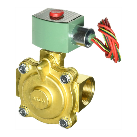
  9. Asco 8210 Series Installation and operating instructions

Asco 8210 Series Installation and operating instructions

ASCO Valves® All Rights Reserved. I&M No. V 5460 R6
©ASCO Valve, Inc.® 50 Hanover Road, Florham Park, New Jersey 07932 www.ascovalve.com
E243264- 2/14
I&M No. V 5460 R6
Installation & Maintenance Instructions
2-WAY INTERNAL PILOT-OPERATED SOLENOID VALVES
NORMALLY OPEN OPERATION - GENERAL SERVICE
1”, 1 /4” OR 1 1/2” NPT
Positioning
This valve is designed to perform properly when mounted in any
position. However, for optimum life and performance, the solenoid
should be mounted vertically and upright to reduce the possibility
of foreign matter accumulating in the solenoid base sub-assembly
area.
Piping
Connect piping to valve according to markings on valve body.
Apply pipe compound or PTFE tape sparingly to male pipe threads
only. If applied to valve threads, the compound may enter the valve
and cause operational difficulty. Avoid pipe strain by properly
supporting and aligning piping. When tightening the pipe, do not
use valve or solenoid as a lever. Locate wrenches applied to valve
body or piping as close as possible to connection point.
CAUTION: To protect the solenoid valve, install a strainer
or filter suitable for the service involved in the inlet side
as close to the valve as possible. Clean periodically
depending on service conditions. See ASCO Series 8600
and 8601 for strainers.
MAINTENANCE
WARNING: To prevent the possibility of severe
personal injury or property damage, turn off
electrical power, depressurize valve, extinguish
all open flames, and avoid any type of sparking
or ignition. Vent hazardous or combustible fluid
to a safe area before servicing the valve.
NOTE: It is not necessary to remove the valve from the pipeline for
repairs.
Cleaning
All solenoid valves should be cleaned periodically. The time
between cleanings will vary depending on the medium and service
conditions. In general, if the voltage to the coil is correct, sluggish
valve operation, excessive noise or leakage will indicate that
cleaning is required. In the extreme case, faulty valve operation will
occur and the valve may fail to open or close. Clean strainer or filter
when cleaning the valve.
Preventive Maintenance
• Keep the medium flowing through the valve as free from dirt
and foreign material as possible.
• While in service, the valve should be operated at least once a
month to insure proper opening and closing.
• Depending on the medium and service conditions, periodic
inspection of internal valve parts for damage or excessive wear
is recommended. Thoroughly clean all parts. If parts are worn
or damaged, install a complete ASCO Rebuild Kit.
Causes of Improper Operation
• Incorrect Pressure: Check valve pressure. Pressure to valve
must be within range specified on nameplate.
• Excessive Leakage: Disassemble valve and clean all parts. If
parts are worn or damaged, install a complete ASCO Rebuild
Kit.
SERIES
8210
8211
DESCRIPTION
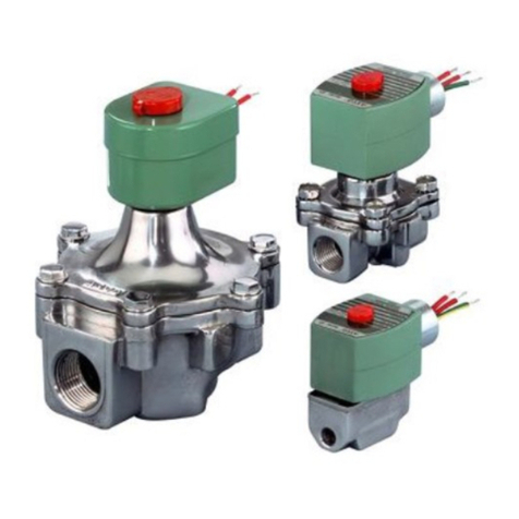
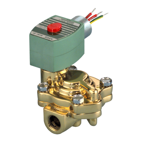
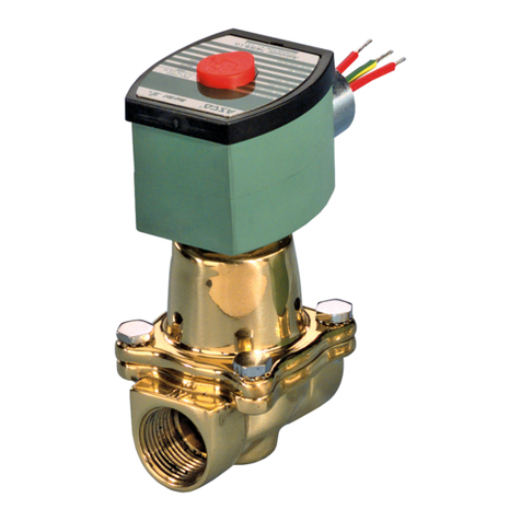
Series 8210 valves are 2-way normally closed, internal pilot
operated solenoid valves designed for general service. Valves are
made of rugged forged brass or die cast stainless steel. Series 8210
valves are provided with a general purpose solenoid enclosure.
Series EF8210 and 8211 are the same as Series 8210 valves except
that they are provided with an explosionproof/watertight solenoid
enclosure.
Notice: Brass valves are not certified as lead-free under the
Safe Water Drinking Act SWDA 1417 and are not intended
for use on drinking water systems. They are intended for
control of water in industrial applications. Consult ASCO
for valves rated for use in potable water applications.
OPERATION
Normally Open: Valve is open when solenoid is de-energized;
closed when energized.
Manual Operator (Optional)
Valves with suffix “MO” in catalog number are provided
with a manual operator which allows manual operation
when desired or during an interruption of electrical
power. To operate valve manually, push in knurled cap
and rotate 180°. Disengage manual operator by rotating
knurled cap counterclockwise 180° before operating electrically.
INSTALLATION
Check nameplate for correct catalog number, pressure, voltage,
frequency, and service. Never apply incompatible fluids or exceed
pressure rating of the valve. Installation and valve maintenance to
be performed by qualified personnel.
Future Service Considerations
Provision should be made for performing seat leakage, external
leakage, and operational tests on the valve with a nonhazardous,
noncombustible fluid after disassembly and reassembly.
Temperature Limitations
For maximum valve ambient and fluid temperatures, refer to chart
below. Check catalog number prefix and watt rating on nameplate.
NOTICE: See separate solenoid installation and maintenance
instructions for information on: Wiring, Solenoid Temperature,
Cause of Improper Operation, Coil or Solenoid Replacement.
Watt
Rating
AC/DC
Catalog
Number
Prefix Solenoid
Class Maximum
Ambient
Temp.
Maximum
Fluid
Temp.
15.4 or 16.1
AC
None, KF,
SF or SC F125 °F
(51.7 °C) 180 °F
(82 °C)
HT, KH, ST or
SU H140 °F
(60 °C) 180 °F
(82 °C)
16.8
DC None or HT F or H 77 °F
(25 °C) 180 °F
(82 °C)
Page 1 of 4
©ASCO Valve, Inc.® 50 Hanover Road, Florham Park, New Jersey 07932 www.ascovalve.com I&M No. V 5460 R6
Valve Disassembly (Refer to Figure 1)
1. Disassemblevalveinanorderlyfashionusingexplodedviews
for identification and placement of parts. Refer to Figure 1
for 1” or 1 ¼” NPT valve constructions or optional manual
operator. Refer to Figure 2” for 1 ½” NPT valve construction.
2. Remove solenoid enclosure. See separate instructions.
3. Unscrew solenoid base sub-assembly using special wrench
adapter supplied in rebuild kit. For special wrench adapter
only, order ASCO Wrench Kit No. K218950.
4. Remove solenoid base sub-assembly, core, plugnut assembly
and solenoid base gasket.
5. Unscrew adapter from valve body, then remove disc holder
assembly, disc holder spring and bonnet gasket.
6. For normal maintenance (cleaning) it is not necessary to
remove the valve seat. However, for valve seat removal use a
7/16” thin wall socket wrench.
7. Optional Manual Operator - It is not necessary to
disassemble the manual operator unless external leakage is
evident. If disassembly is required, remove retainer using a
suitable pair of retaining ring pliers. Then remove flat washer
and back out manual operator stem counterclockwise with
stem gasket attached.
8. Remove bonnet screws, valve bonnet, diaphragm
spring, diaphragm assembly, body gasket, body passage
eyelet(present on current valve constructions only) and body
passage gasket.
9. All parts are now accessible for cleaning or replacement.If
parts are worn or damaged, install a completeASCO Rebuild
Kit.
-- Service Notice --
When installing a new ASCO Rebuild Kit, the parts supplied are
shown in Figures 1 and 2. The parts supplied are new, improved
and a direct replacement for the present parts providing all new
parts are installed.
CAUTION: To ensure proper valve operation, install all
parts supplied in ASCO Rebuild Kit. Do not mix old and
new parts.
Valve Reassembly
1. Lubricate body gasket, body passage gasket, bonnet gasket
and solenoid base gasket with DOW CORNING® 200 Fluid
lubricant or an equivalent high-grade silicone fluid.
2. Optional Manual Operator - Lubricate stem gasket with
DOWCORNING®111 Compound lubricantoran equivalent
high-grade silicone grease.
3. Install body passage gasket, body passage eyelet, diaphragm
assembly, diaphragm spring, valve bonnet and bonnet screws.
Hand thread screws as far as possible. Then torque bonnet
screws in a crisscross manner to 144 ± 15 in-lbs [16,3 ± 1,7
Nm].
4. If removed, install valve seat in valve body. Apply a small
amount of thread compound compatible with valve media to
valve seat threads. Torque valve seat to 75 ± 10 in--lbs [8,5 ±
1,1 Nm].
5. Install bonnet gasket, disc holder spring, disc holder assembly
and adapter in valve body. Torque adapter to 175 ± 25 in--lbs
[19,8 ± 2,8 Nm].
6. Replace solenoid base gasket, plugnut assembly, core (small
end up) and solenoid base sub-assembly. Torque solenoid
base sub-assembly to 175 ± 25 in-lbs [19,8 ± 2,8 Nm].
7. Optional Manual Operator - If removed, install stem
with stem gasket clockwise into valve body using a suitable
screwdriver. Reinstall flat washer and retainer. Then turn
manual operator stem counterclockwise until it stops. This is
the position for electrical operation.
8. Install solenoid. See separate instructions.
WARNING: To prevent the possibility of death,
serious injury or property damage, check valve for
proper operation before returning to service. Also
perform internal seat and external leakage tests
with a non-hazardous, noncombustible fluid.
9. Restore line pressure and electrical power supply to valve.
10. Aftermaintenance is completed,operatethe valve afewtimes
to be sure of proper operation. A metallic click signifies that
the solenoid is operating.
ORDERING INFORMATION
FOR ASCO REBUILD KITS
Parts marked with an asterisk(*) in the exploded view are supplied
in Rebuild Kits. When Ordering Rebuild Kits for ASCO Valves,
order the Rebuild Kit number stamped on the valve nameplate. If the
number of the kit is not visible, order by indicating the number of kits
required, and the Catalog Number and Serial Number of the valve(s)
for which they are intended.
Part Name Torque Value
Inch-Pounds
Torque Value
Newton-Meters
Solenoid base
sub-assembly 175 ± 25 19,8 ± 2,8
Adapter
Bonnet screws 144 ± 15 16,3 ± 1,7
Valve seat 75 ± 10 8,5 ± 1,1
Torque Chart
Page 2 of 4
©ASCO Valve, Inc.® 50 Hanover Road, Florham Park, New Jersey 07932 www.ascovalve.com I&M No. V 5460 R6
Page 3 of 4
stem retainer
stem washer
manual operator
stem
stem gasket
MANUAL OPERATOR
(OPTIONAL)
body gasket
Indicates Parts Supplied In
ASCO Rebuild Kits
solenoid base
sub--assembly
core (small end up)
plugnut assembly
solenoid base gasket
adapter
disc holder assembly
disc holder spring
bonnet gasket
valve seat
diaphragm spring
valve bonnet
Special wrench adapter for
solenoid base
sub--assembly
(order Kit No. K218950)
IMPORTANT
See torque
chart
diaphragm assembly
For stainless steel valves: washer (4)
For stainless steel valves: socket head screws (4)
For brass valves:
bonnet screw (4)
hex head
Figure 1. Series 8210 valve without solenoid, 1 or 1 ¼ NPT valve with manual operator shown.
valve body
body passage gasket
body passage eyelet
©ASCO Valve, Inc.® 50 Hanover Road, Florham Park, New Jersey 07932 www.ascovalve.com I&M No. V 5460 R6
Page 4 of 4
valve seat
Indicates Parts Supplied In
ASCO Rebuild Kits
Special wrench adapter
for solenoid base
sub-assembly
(order Kit No. K218950)
solenoid base
sub--assembly
core (small end up)
plugnut assembly
solenoid base gasket
adapter
disc holder assembly
disc holder spring
bonnet gasket
valve body
body passage gasket
eyelet
body gasket
IMPORTANT
See torque
chart
diaphragm assembly
For stainless steel valves: washer (4)
For stainless steel valves: socket head screws (4)
Figure 2. Series 8210 valve without solenoid, 1 ½” NPT valve shown.
diaphragm spring
valve bonnet
For brass valves:
bonnet screw (4)
hex head

This manual suits for next models

2

Other Asco Control Unit manuals

Asco 8344 Series User manual

Asco

Asco 8344 Series User manual

Asco 298 Series User manual

Asco

Asco 298 Series User manual

Asco RedHat 8314 Series Installation and operating instructions

Asco

Asco RedHat 8314 Series Installation and operating instructions

Asco 8214G54 Installation and operating instructions

Asco

Asco 8214G54 Installation and operating instructions

Asco 8030 Series Installation and operating instructions

Asco

Asco 8030 Series Installation and operating instructions

Asco 8314 Series Installation and operating instructions

Asco

Asco 8314 Series Installation and operating instructions

Asco 8267 Series Installation and operating instructions

Asco

Asco 8267 Series Installation and operating instructions

Asco FLOWTRONIC D 60701073 User manual

Asco

Asco FLOWTRONIC D 60701073 User manual

Asco RedHat 8321 Series Installation and operating instructions

Asco

Asco RedHat 8321 Series Installation and operating instructions

Asco Numatics 502 User manual

Asco

Asco Numatics 502 User manual

Asco 290 Series Instruction Manual

Asco

Asco 290 Series Instruction Manual

Asco 8316 Series Installation and operating instructions

Asco

Asco 8316 Series Installation and operating instructions

Asco 290 Series User manual

Asco

Asco 290 Series User manual

Asco 8222 Series Installation and operating instructions

Asco

Asco 8222 Series Installation and operating instructions

Asco F210 Series Installation and operating instructions

Asco

Asco F210 Series Installation and operating instructions

Asco Aseptic Positioner D Series Instruction Manual

Asco

Asco Aseptic Positioner D Series Instruction Manual

Asco 8342 series Instruction Manual

Asco

Asco 8342 series Instruction Manual

Asco JOUCOMATIC R294 Series User manual

Asco

Asco JOUCOMATIC R294 Series User manual

Asco 8003P Series Installation and operating instructions

Asco

Asco 8003P Series Installation and operating instructions

Asco 8262 series Installation and operating instructions

Asco

Asco 8262 series Installation and operating instructions

Asco RedHat 8223 Series Installation and operating instructions

Asco

Asco RedHat 8223 Series Installation and operating instructions

Asco 8401 Series User manual

Asco

Asco 8401 Series User manual

Asco 262 Series User manual

Asco

Asco 262 Series User manual

Asco 8040 Series Installation and operating instructions

Asco

Asco 8040 Series Installation and operating instructions

Popular Control Unit manuals by other brands

Niko 340-00111 manual

Niko

Niko 340-00111 manual

Flomatic Comboair installation instructions

Flomatic

Flomatic Comboair installation instructions

Nordson EFD 736HPA Maintenance & Parts Guide

Nordson EFD

Nordson EFD 736HPA Maintenance & Parts Guide

elsner elektronik IMSG 230 compact Technical specifications and installation instructions

elsner elektronik

elsner elektronik IMSG 230 compact Technical specifications and installation instructions

CALEFFI 510 Series quick start guide

CALEFFI

CALEFFI 510 Series quick start guide

Chroma Uploader II quick start guide

Chroma

Chroma Uploader II quick start guide

HKS Super SQV IV 71008-AK001 manual

HKS

HKS Super SQV IV 71008-AK001 manual

Niobrara QUCM 3964 Installation and programming manual

Niobrara

Niobrara QUCM 3964 Installation and programming manual

WEG DBW03 Series user manual

WEG

WEG DBW03 Series user manual

EOS ECON A2 Installation and user manual

EOS

EOS ECON A2 Installation and user manual

ExTox ET-1D Series instruction manual

ExTox

ExTox ET-1D Series instruction manual

Huawei MU509-b Application guide

Huawei

Huawei MU509-b Application guide

Spirax Sarco 5953 Series Installation and maintenance instructions

Spirax Sarco

Spirax Sarco 5953 Series Installation and maintenance instructions

H3C PSR450-12A user manual

H3C

H3C PSR450-12A user manual

Seraphim SRP-XXX-6PA-BB installation guide

Seraphim

Seraphim SRP-XXX-6PA-BB installation guide

Parker Racor RK19506 instructions

Parker

Parker Racor RK19506 instructions

Festo CDVI5.0 Assembly instructions

Festo

Festo CDVI5.0 Assembly instructions

Bartec APEX px operating instructions

Bartec

Bartec APEX px operating instructions

manuals.online logo
manuals.online logoBrands
  • About & Mission
  • Contact us
  • Privacy Policy
  • Terms and Conditions

Copyright 2025 Manuals.Online. All Rights Reserved.