manuals.online logo
Brands
  1. Home
  2. •
  3. Brands
  4. •
  5. ATEN
  6. •
  7. Control Unit
  8. •
  9. ATEN Altusen PN9108A User manual

ATEN Altusen PN9108A User manual

This manual suits for next models

1

Other ATEN Control Unit manuals

ATEN Altusen KN9000 User manual

ATEN

ATEN Altusen KN9000 User manual

ATEN CN8000 User manual

ATEN

ATEN CN8000 User manual

ATEN CN-6000 User manual

ATEN

ATEN CN-6000 User manual

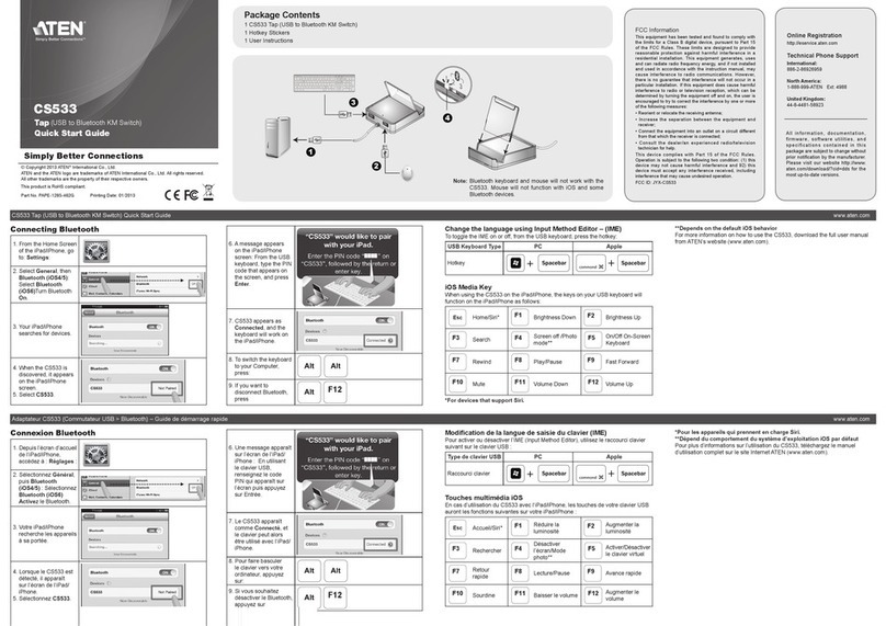
ATEN cs533 User manual

ATEN

ATEN cs533 User manual

ATEN CN-6000 User manual

ATEN

ATEN CN-6000 User manual

ATEN KA7171 User manual

ATEN

ATEN KA7171 User manual

ATEN CN8000 User manual

ATEN

ATEN CN8000 User manual

ATEN CN-5000 User manual

ATEN

ATEN CN-5000 User manual

ATEN CN8000 User manual

ATEN

ATEN CN8000 User manual

ATEN PE4104AJ User manual

ATEN

ATEN PE4104AJ User manual

ATEN KVMP CM1164 User manual

ATEN

ATEN KVMP CM1164 User manual

Popular Control Unit manuals by other brands

Seitz 14A80 user manual

Seitz

Seitz 14A80 user manual

Wilo RS485 Installation and operating instructions

Wilo

Wilo RS485 Installation and operating instructions

Becker CentralControl CC41 Commissioning Instruction

Becker

Becker CentralControl CC41 Commissioning Instruction

SICK CDB650 operating instructions

SICK

SICK CDB650 operating instructions

Panduit NetKey NKP5E88M Series installation instructions

Panduit

Panduit NetKey NKP5E88M Series installation instructions

MX Options Concentric Petite Fitting instructions

MX

MX Options Concentric Petite Fitting instructions

Clean Water Systems Fleck 2510 Installation & start?up guide

Clean Water Systems

Clean Water Systems Fleck 2510 Installation & start?up guide

Fairchild FSB44104A user guide

Fairchild

Fairchild FSB44104A user guide

LEGRAND Wattstopper LMIN-104 installation instructions

LEGRAND

LEGRAND Wattstopper LMIN-104 installation instructions

PMK ATT10BNCS instruction manual

PMK

PMK ATT10BNCS instruction manual

Tektronix TDS3FFT user manual

Tektronix

Tektronix TDS3FFT user manual

Woodward easYgen Technical manual

Woodward

Woodward easYgen Technical manual

Balluff BNI EIP-502-105-R015 user guide

Balluff

Balluff BNI EIP-502-105-R015 user guide

NXP Semiconductors TWR-LS1021A Getting started

NXP Semiconductors

NXP Semiconductors TWR-LS1021A Getting started

Advantech PCM-3117 Startup manual

Advantech

Advantech PCM-3117 Startup manual

Danfoss MCO 101 manual

Danfoss

Danfoss MCO 101 manual

Moons' Lin Engineering R701P user manual

Moons'

Moons' Lin Engineering R701P user manual

Aventics RV1 operating instructions

Aventics

Aventics RV1 operating instructions

manuals.online logo
manuals.online logoBrands
  • About & Mission
  • Contact us
  • Privacy Policy
  • Terms and Conditions

Copyright 2025 Manuals.Online. All Rights Reserved.

• 1 PN9108 Station
• 1 PN9108 to AC Source Power Cord (1.8M)
• 8 Power Outlet Power Cords
• 8 Safe Shutdown Cables
• 1 PON Cable (DB9 F to DB9 M)
• 4 Foot Pads
• 1 Rack mount kit
(Brackets and Philips Head Hex M3 x 8 Screws)
• 1 User Instructions
• 1 Software Disk
The complete package consists of:
Package Contents
1
The PN9108 Unit ( Rear View )
3
1. Power Socket
2. Circuit Breaker
3. AC Power Outlets
4. RS-232 Port
5. Safe Shutdown Ports
Single Stage Installation
4. Use the AC power cord provided with this package to connect the PN9108’s Power
Socket to an AC power source.
5. Turn on the PN9108.
6. Turn on the computers.
2The PN9108 Unit ( Front View )
1. Port LEDs
2. Current LED
3. Station ID LED
4. 10/100 Mbps Data LED
5. Power LED
6. Power Control Buttons
7. Current Display Switch
8. Reset Switch
9. Link LED
7 8 9
6
1
2 3 4 5
9
351 6
8
4
7
2
4-1
These instructions show how to install the PN9108 Power over the NET. For detailed
information, refer to the user manual included in the kit.
53
2
1
Power cord : The power source is a 220- 240 V AC supply, use a tandem (T blade) type
attachment plug with ground conductor power cord that meets the respective European
country's safety regulations, such as VDE for Germany. Plug should comply with the VDE
0620 specification; the connector should comply with the VDE 0625 specification. A
minimum 10A, 0.75 mm2 x 3G power cord (H05VV-F or VW-1) should be used.
Power outlet cord : Connector should comply with the VDE 0625 or EN60320
specification. A minimum 10A, 0.75 mm2 x 3G power cord (H05VV-F or VW-1) should
be used.
Note:
Use the power cord supplied with this package. If you need to purchase additional
power cord, you must choose ones that comply with the above specifications.
6. PON (Power over the NET) Output Port
7. Power Switch
8. RJ-45 Port
9. PON Input Port Daisy Chaining Installation
To manage even more computers, up to 15 additional PN9108 Stations can be daisy
chained down from the top level unit. In this way, up to 128 computers can be managed
on a complete installation.
Note: In a daisy chained installation, a switch is the child of the switch above it, and the
parent of the switch below.
5
Single Stage Installation
4
1. For each computer, use an AC Output cable to connect from any available PN9108 output
port to the computer’s AC socket.
2. For Windows 98E, ME, NT, 2000, XP, and 2003 Server computers, for each computer
use a Safe Shutdown cable to connect from the PN9108’s Safe Shutdown port to the
computer’s Serial port.
3. Plug the LAN or WAN cable into the PN9108’s RJ-45 socket.
Important Notice
Considering environmental protection, ATEN does not provide a fully printed user manual for this product. If
the information contained in the Quick Start Guide is not enough for you to configure and operate your
product, please visit our website www.aten.com, and download the full user manual.
Power over the NET (PN9108 / PN9108U)
Quick Start Guide
All information, documentation, firmware, software utilities, and specifications contained in this package are subject to change without prior
notification by the manufacturer. Please visit our website http://www.aten.com/download/?cid=dds for the most up-to-date versions.
Online Registration
• http://eservice.aten.com
Technical Phone Support
International:
• 886-2-8692-6959
China:
• 86-10-5255-0110
Japan:
• 81-3-5615-5811
Korea:
• 82-2-467-6789
North America:
• 1-888-999-ATEN Ext: 4988
United Kingdom:
• 44-8-4481-58923
ATEN Altusen™
© Copyright 2015 ATEN® International Co., Ltd. www.aten.com
Altusen and the Altusen logo are trademarks of ATEN International Co., Ltd.
All rights reserved. All other trademarks are the property of their respective owners.
This product is RoHS compliant PAPE-1214-B01G Printing Date: 01/2015
6Rack Mounting
2. Screw the rack mounting brackets into the front and rear modules.
3. Screw the mounting brackets to the rack.
7
If you are the administrator, and are logging in for the first time, use the default Username:
administrator; and the default Password: password.
After you have successfully logged in, the PN9108 Main Screen appears:
Browser operation
The most convenient way to operate the PN9108 is with an internet browser.
To begin:
To ascertain and set an IP address for your device when it is assigned
automatically via DHCP:
• Run IPInstaller.exe (included in our software CD)
• Click "Enumerate" to refresh the Device List if
necessary
• Select the device
• Select "Obtain an IP address automatically
(DHCP)"
• Click "Set IP" and wait for the IP setting
procedure to finish
If your installation uses fixed IP addresses, select " Specify an IP address", key in the
appropriate IP information for the IP address, Submask, and Gateway, then click " Set IP"
1. Open your browser and specify the IP address of the PN9108 you want to access in the
browser’s URL location bar.
2. A Security Alert dialog box appears. Accept the certificate. A login dialog box, like the one
below, appears:
1. Separate the front and rear modules by removing the four module attaching screws.
3. Provide a valid Username and Password (set by the PN9108 administrator), then Click Login
to continue.
Note:
For security purposes, we strongly recommend you remove these and give yourself a
unique Username and Password with the appropriate Administrator permissions. This
setting can be found under "General" setting in the main screen.
Specifications
8
Function PN9108A PN9108G
Power Characteristics 100–240 VAC; 15A* 100–240 VAC; 10A**
Power Inlet 1 x IEC 60320/C14 (M)
Power Outlets 8 x IEC 60320/C13 (F)
I/P Rating (Total input -max) 100–120 V AC; 50/60Hz; 12A 220–240 V AC; 50/60Hz; 10A
O/P Rating Per Port (max) 100–120 V AC; 50/60Hz; 9A 220–240 V AC; 50/60Hz; 9A
Total (max) 100–120 V AC; 50/60Hz; 11A 220–240 V AC; 50/60Hz; 9A
LEDs
Outlet Power 8 (orange)
Remote Access 8 (green)
Link 1 (green)
10/100 Mbps 1 (orange/green)
Power 1 (blue)
Current 1 (red)
Station ID 2 x 7 segment (yellow)
Connectors
PON In 1 x DB-9 (F)
PON Out 1 x DB-9 (M)
LAN 1 x RJ-45
RS-232 1 x DB-9 (M)
Safe Shutdown 8 x 6-pin Safe Shutdown Jacks (F)
Switches
Power 1 x Rocker
Outlet On / Off
Remote On / Off 8 x Pushbutton
Sta. ID Display 1 x Pushbutton
Reset 1 x Semi hidden
Power Consumption (no load) 120V; 60Hz; 16W 230V; 50Hz; 16W
Power Consumption (max. load) 120V; 60Hz; 1440W 230V; 50Hz; 2300W
Environment
Physical
Properties
0 - 40˚C Operating Temp.
-20 - 60˚C Storage Temp.
0 - 80% RH, Non-condensingHumidity
MetalHousing
Weight 4.2 kg
Dimensions
(L x W x H)
43.24 x 25.42 x 4.40 cm (19”/1U)
* Units are certified to 80% of max. current rating (100-120 VAC).
** Units are certified to 220-240 VAC.