manuals.online logo
Brands
  1. Home
  2. •
  3. Brands
  4. •
  5. Clemco
  6. •
  7. Tools
  8. •
  9. Clemco HOLLO-BLAST User manual

Clemco HOLLO-BLAST User manual

Other Clemco Tools manuals

Clemco 24189 User manual

Clemco

Clemco 24189 User manual

Clemco PIPE-PRO XL User manual

Clemco

Clemco PIPE-PRO XL User manual

Popular Tools manuals by other brands

AGI Westfield MKX16 Assembly manual

AGI

AGI Westfield MKX16 Assembly manual

GYS HAND-DUCTION 056923 Translation of the original instructions

GYS

GYS HAND-DUCTION 056923 Translation of the original instructions

Grizzly H7583 instruction manual

Grizzly

Grizzly H7583 instruction manual

Sealey VS0462.V2 instructions

Sealey

Sealey VS0462.V2 instructions

Makita HR2650 instruction manual

Makita

Makita HR2650 instruction manual

Forza 1100H Series manual

Forza

Forza 1100H Series manual

Aventics EBS-PI operating instructions

Aventics

Aventics EBS-PI operating instructions

Martor SECUNORM 175 quick start guide

Martor

Martor SECUNORM 175 quick start guide

jbc N4473 instruction manual

jbc

jbc N4473 instruction manual

FEINMETALL FZWZ-SET-001 quick start guide

FEINMETALL

FEINMETALL FZWZ-SET-001 quick start guide

Worx Professional Sonicrafter WU676 Original instructions

Worx Professional

Worx Professional Sonicrafter WU676 Original instructions

Gage Bilt GB713SH Original instructions

Gage Bilt

Gage Bilt GB713SH Original instructions

Hilti DX 9-ENP Original operating instructions

Hilti

Hilti DX 9-ENP Original operating instructions

norbar NORTRONIC 34399 Operator's manual

norbar

norbar NORTRONIC 34399 Operator's manual

BGS technic 8578 manual

BGS technic

BGS technic 8578 manual

axing BWZ 5-02 Operation instructions

axing

axing BWZ 5-02 Operation instructions

Makita DHR241 instruction manual

Makita

Makita DHR241 instruction manual

Motor Guard JMB-1250 instructions

Motor Guard

Motor Guard JMB-1250 instructions

manuals.online logo
manuals.online logoBrands
  • About & Mission
  • Contact us
  • Privacy Policy
  • Terms and Conditions

Copyright 2025 Manuals.Online. All Rights Reserved.

Revision: 01.2015
Clemco
International GmbH Carl-Zeiss-Straße 21 Tel.: +49 (0) 8062 –90080
83052 Bruckmühl Mail: info@clemco.de
Germany Web: www.clemco-international.com
Owner´s manual
HOLLO-BLAST
INTERNAL-PIPE BLAST TOOL
HOLLO-BLAST Page 1
INTERNAL- PIPE BLAST TOOL
HOLLO-BLAST
INTERNAL-PIPE BLAST TOOL
O. M. 06158
Do not proceed with
these instructions*
until you have READ
the orange cover of
this MANUAL and YOU
UNDERSTAND its
contents.
These WARNINGS are
included for the health
and safety of the
operator and those in
the immediate vicinity.
*If you are using a Clemco Distributor
Maintenance and Part Guide, refer to
the orange warnings insert preceding
the Index before continuing with the
enclosed instructions.
Electronic files include a Preface
containing the same important
information as the orange cover.
WARNING
HOLLO-BLAST Page 2
INTERNAL- PIPE BLAST TOOL
1.0 INTRODUCTION
1.1 Scope
1.1.1 These instructions cover set-up, operation,
maintenance, troubleshooting, and replacement parts for
Clemco’s Hollo-Blast internal pipe blasting tool.
1.1.2 These instructions contain important information
required to safely operate of the Hollo-Blast tool. The tool
requires a blast machine and accessories to deliver the blast
stream to the tool. Before using the Hollo-Blast all personnel
associated with the operation must read this entire manual,
including the orange cover, and have knowledge of how to
safely operate the blast machine and all accessories.
1.1.3 All personnel involved with the abrasive blasting
process must be made aware of the hazards associated with
abrasive blasting. The Clemco booklet Abrasive Blasting
Safety Practices(Stock No. 22090) also available in Spanish
(Stock No. 22931) contains important safety information about
abrasive blasting that may not be included in equipment
operation manuals. To request additional copies, email
info@clemco.de.
1.2 Safety Alerts
1.2.1 Clemco uses safety alert signal words, based on
ANSI Z535.4-2011, to alert the user of a potentially hazardous
situation that may be encountered while operating this
equipment. ANSI's definitions of the signal words are as
follows:
This is the safety alert symbol. It is
used to alert you to potential physical
injury hazards. Obey all safety
messages that follow this symbol to
avoid possible injury or death.
NOTICE
Notice indicates information that is considered
important, but not hazard-related, if not avoided,
could result in property damage.
CAUTION
Caution indicates a hazardous situation that, if not
avoided, could result in minor or moderate injury.
WARNING
Warning indicates a hazardous situation that,
if not avoided, could result in death or serious
injury.
DANGER
Danger indicates a hazardous situation that,
if not avoided, will result in death or serious
injury.
1.3 Theory of Operation
1.3.1 Refer to Figure 1. When correctly connected to
a blast hose and lance, and the blast machine is
pressurized, the blast stream flows through the tool and
deflects off the deflection tip. This spreads the blast
stream into a 360oblast pattern, cleaning the inside of
the pipe without having to rotate it.
Figure 1
2.0 ANCILLARY EQUIPMENT REQUIREMENTS
2.1 Blast Machine and Accessories.
2.1.1 The Hollo-Blast tool attaches to the end of a
pipe lance (section(s) of 1-1/4" NPT rigid pipe) and blast
hose in place of a standard nozzle.
2.1.2The blast machine should have a minimum
external piping size of 1-1/4" inside diameter (ID), a
blast hose assembly with a minimum of 1-1/4" ID, and
quick couplings on both ends (Refer to Section 2.4 for
Deflection Tip
Lance Coupling
Lance provided by user
Gasket
Blast stream enters
through the lance
Blast stream deflects off tip
into 360opattern
HOLLO-BLAST Page 3
INTERNAL- PIPE BLAST TOOL
exceptions). The blast hose should be long enough to feed
the lance from the pipe’s entrance to the far end.
2.2 Centering Devices
2.2.1 The tool will blast the inside of 2-inch ID pipe without
using a centering carriage.
2.2.2Use one of the following carriages to center the tool
in larger diameter pipe.
Stock No. 01124, Model HBC-1 Collar and Button Set
centers the tool in 3" to 5" ID pipe. Refer to Section 3.1.
Stock No. 01131, Model HBC-2 Adjustable Carriage fully
adjustable carriage centers the tool in 5" through 12" ID
pipe. Refer to Section 3.2.
2.3 Compressed Air Requirements
2.3.1 The compressor and air supply lines must be sized to
support a blast operation at the pressure and cfm shown in
the air consumption table below. The cfm consumption shown
are approximate and are based on blasting with pressure set
at 100 psi.
Nozzle Orifice New Nozzle Worn Nozzle
Stock No. Size and Sleeve and Sleeve
01406
1/2"
200 cfm
340 cfm
01407
5/8"
350 cfm
550 cfm
Nozzles are considered worn out when the orifice
increases by 1/16". Carbide sleeves are considered
worn out when they are worn to about 1/4".
2.4 Pipe Lance Provided by User
2.4.1 The purpose of the lance
2.4.1.1 The lance is section(s) of 1-1/4" NPT pipe that
fits between the blast hose and Hollo-Blast tool, and is
usually the same length as the pipe being blasted.
2.4.1.2The rigid pipe lance provides a means to feed
the tool through the pipe. It also affords a straight path
for the blast stream to enter the tool, which prevents hot
spots and uneven wear. The only application in which a
lance may not required is where the ID of the pipe is
between 3" and 5" (in this situation the blast hose will
not form a bend), and the pipe is short enough to feed
the hose without the use of a rigid lance. This exception
is shown in Figure 2. Otherwise a lance is always
recommended.
2.4.1.3 A lance must be used on larger diameter pipe
because the blast hose will bend near the point of
attachment to the tool. Such a bend disrupts the smooth
flow of the blast stream to the deflection tip, and leads
to excessively rapid wear. A smooth, straight path into
the tool is essential for optimum performance.
Figure 2
Hollo-Blast Tool
Stock No 01124 Collar & Button Centering Carriage
1-1/4" Threaded Nozzle Holder
Although Blast hose with gradual radius is acceptable for short lengths
of small diameter pipe, use of a pipe lance is generally recommended.
5" ID Pipe Max.
Avoid this setup. Tight bends cause rapid
wear along the outside radius of the hose and
uneven wear inside the tool.
Stock No 01124 Adjustable
Centering Carriage
Nozzle Washer
HOLLO-BLAST Page 4
INTERNAL- PIPE BLAST TOOL
2.4.2 Lance setup
2.4.2.1 The Hollo-Blast has a 1-1/4" NPS-F threaded
connection at the entrance of the tool to accommodate the
pipe lance. The first two or three feet of the lance should
be schedule-160 heavy-walled pipe. The heavy wall
compresses the gasket better than thin-walled pipe, and
protects the entrance of the tool from the abrasive
stream better than light-walled schedule-40 pipe. The
illustrations in Figures 3 A-C show typical lance setups.
Each uses the schedule-160 heavy-walled lance attached
to the tool and standard schedule-40 pipe to make up the
difference. Standard schedule-40, 1-1/4" pipe, comes in 21
ft. lengths. Use multiple lengths coupled as shown in
Figures 3-B and 3-C to obtain the required length.
Figure 3-A
Figure 3-B
Figure 3-C
Hollo-Blast Tool
Pipe Coupling
Short Length of 1-1/4"
Schedule-160 Pipe
Standard, 1-1/4"Schedule-40 Pipe
coupled with 00551 Coupling
1-1/4" Blast Hose coupled with
quick couplings on both ends
00869 Nozzle Washer
Short length of 1-1/4"
Schedule 160 Pipe
1-1/4" Blast Hose coupled with
1-1/4" threaded nozzle holder
00869 Nozzle Washer
This is the basic setup. Alone it may be used to blast short lengths (three to five feet) of pipe or cylinders.
Longer lengths of schedule 160 could be cost prohibitive and cause undo wear on heavy walled pipe.
This setup is suitable for blasting lengths
of 2” ID to 3-1/4” ID pipe, or 25 foot lengths of larger diameter pipe.
This setup should be used when multiple lances are required
for blasting longer lengths of 3-1/2" and larger diameter pipe.
Hollo-Blast Tool
Hollo-Blast Tool
00869 Nozzle Washer
Short Length of 1-1/4"
Schedule-160 Pipe
Standard, 1-1/4"Schedule-40 Pipe
Coupled with 00551 Couplings on both ends
1-1/4" Blast Hose Coupled with
Quick Couplings on Both Ends
00551 Coupling
11203 Lock Pins
Revision: 01.2015
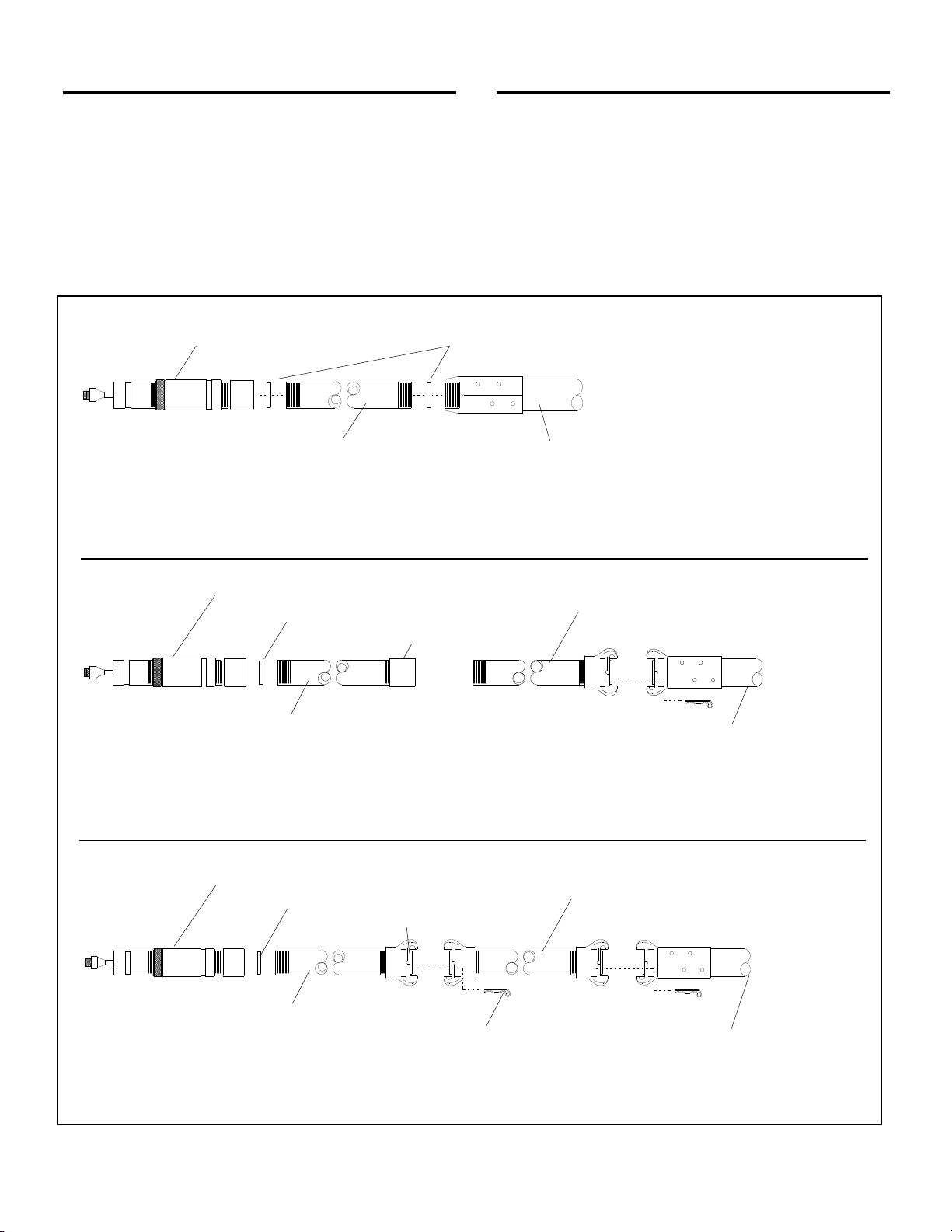
Figure 3-A is the basic setup; it should be used with all lance
setups. Alone it is suitable for blasting short lengths (the
length of the heavy-walled lance) of pipe or cylinders.
Figure 3-B is the basic setup, plus additional standard 1-1/4
pipe lance, attached with threaded pipe couplings. This setup
uses standard threaded pipe couplings to connect the lance
sections together. Using threaded pipe couplings allows it to
fit inside of 3-1/4" diameter and smaller pipe where a quick
coupling will not fit. The threaded couplings require the lance
be screwed on or off when adding or removing sections. The
threads are prone to galling, so the setup in Figure 3-C should
be used whenever possible.
Figure 3-C is the basic setup, plus additional standard 1-1/4
pipe lances, attached with quick couplings. This uses quick
couplings to connect lance sections together. Quick couplings
eliminate the need to rotate the lance when adding or
removing sections. It is limited to use with pipe diameters that
are 3-1/2" diameter and larger that will accommodate the
quick couplings.
2.5 Abrasive
2.5.1 DO NOT USE abrasives containing more than one
percent crystalline (free) silica. Obtain safety data sheets
(SDS) for the blasting abrasive prior to blasting, paying
particular attention the health risks and presence of any
hazardous/toxic substances. Use only abrasives specifically
manufactured for blasting, and that are compatible with the
surface being blasted. Abrasive produced for other
applications may be inconsistent in size and shape, and
contain particles that could jam the abrasive metering valve,
or cause irregular wear. Steel grit is an ideal media to use if
adequate recovery means are available.
2.5.2 Silicon Carbide, Aluminum Oxide, and Garnet:
Aggressive abrasives such as these should be avoided unless
required by job specification. Service life will be reduced
on any components which come in contact with these
abrasives. When an aggressive abrasive must be used,
use a boron carbide or composite deflection tip and
boron sleeves. Boron tips may chip when using large,
aggressive abrasive. Use a composite tip for 36-mesh
and coarser aggressive abrasive.
2.5.3 Abrasive Size
2.5.3.1 The choice of abrasive size depends on the
desiredprofile,cleaningrate,andnozzlesize.Generally,
larger and denser abrasives provide a deeper profile,
whilesmaller abrasivescleanfaster.Withthe 1/2" orifice
nozzle, use 25-mesh and finer; with the 5/8" orifice
nozzle, use 16-mesh and finer.
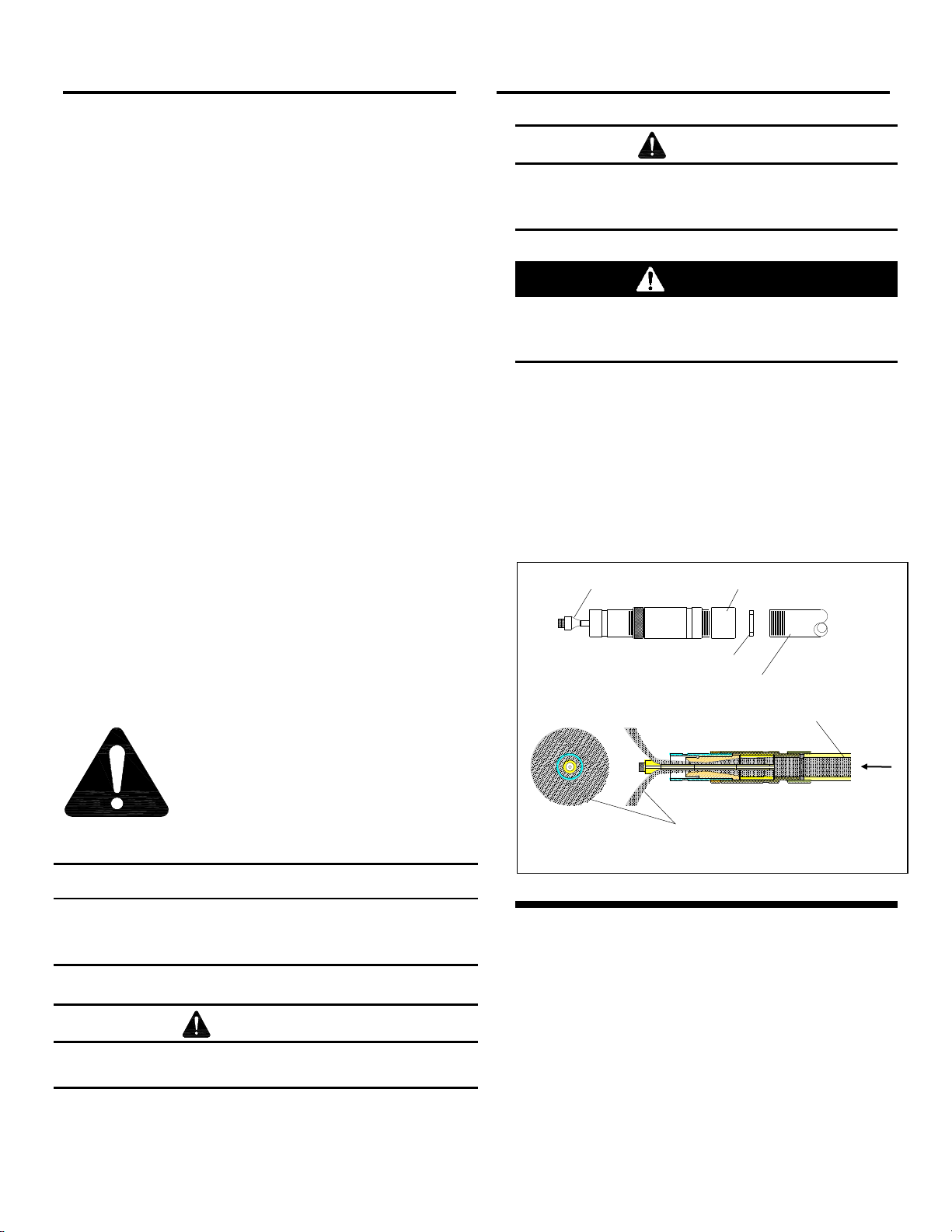
3.0 Attach Centering Device
3.1 Collar and Buttons, 3" to 5", Model HBC-1
Figures 4-A and 4-B
Collars without buttons fit inside 2-3/4" ID pipe, which
must be smooth and without seams or other
protrusions.
3.1.1 The set comes with two collars of different
inside diameters and six each of four different length
buttons to center the tool in 3" to 5" pipe. Refer to the
following steps for assembly. Additional collar and
buttons could be used to support the lance.
1. Slide the front collar over the tip protection sleeve. Align the collar setscrew with the groove in the protection
sleeve. Using the 3/16" hex key provided, tighten the setscrew to secure. Repeat the process to secure the
rear collar to the tool holder.
Figure 4-A
Front Collar has smaller
inside diameter
Rear Collar has larger
inside diameter
Tip Protection Sleeve
Tool Holder
Set Screw
Set Screw
HOLLO-BLAST Page 6
INTERNAL- PIPE BLAST TOOL
2. Determine which set of buttons centers the tool best and install them into the collars as shown.
Figure 4-B
3.2 Adjustable Centering Carriage 5" to 12"
Model HBC-2 Figures 5-A through 5-I
3.2.1 This carriage is completely adjustable to center
the tool in 5" to 12" pipe. Refer to the following 10 steps
for assembly.
1. Using the 3/16" hex key provided, loosen the setscrew, and then remove the knurled lock-ring and threaded
sleeve.
Figure 5-A
2. Loosen the knurled lock-ring on the chrome tip protection sleeve.
Figure 5-B
Push the buttons into the holes on the
collars; each button snaps into position.
Pull to remove.
In some cases the tool may
be too tight in the pipe. In
those situations, position the
collar as shown and place a
shorter button at the top.
Knurled Lock-Ring
Chrome Tip Protection Sleeve
Tool Holder
Threaded Sleeve
Setscrew
Knurled Lock-Ring
Carriage Collar
HOLLO-BLAST Page 7
INTERNAL- PIPE BLAST TOOL
3. Unscrew the chrome tip protection sleeve to remove it from tool holder assembly. It may be necessary to hold
the nozzle while the chrome sleeve is removed to prevent the nozzle and deflection tip assembly from coming
out of the tool holder. Note: The o-ring may slide off the nozzle, if so, retrieve it from inside the chrome sleeve
and place into nozzle groove.
Figure 5-C
4. Position the knurled lock-ring at about the middle of the threaded sleeve.
5. Make sure the o-ring is in place in the nozzle o-ring groove.
Figure 5-D
6. Screw the threaded sleeve into the tool holder until it is tightly seated against the nozzle flange. Make sure it is the
sleeve that is seated against the nozzle, and not the knurled lock ring seated against the tool holder. Rapid wear
on the nozzle and tool holder will occur if the tool holder is not tight against the nozzle flange.
Figure 5-E
7. Screw the lock-ring tightly against the tool holder to lock the threaded sleeve.
Figure 5-F
O-Ring
Tighten lock-ring against tool holder
Knurled Lock-Ring
Screw threaded sleeve into tool holder
Tool Holder
Nozzle Flange
Tool Holder
Nozzle
O-Ring
Chrome Tip Protection Sleeve
Knurled Lock-Ring
O-Ring Groove
HOLLO-BLAST Page 8
INTERNAL- PIPE BLAST TOOL
8. From the rear of the carriage, insert the reassembled tool through the carriage collar and yoke as shown.
Align the groove in the tool holder with collar setscrew, and tighten the setscrew to secure.
Figure 5-G
9. Screw the remaining lock-ring onto the threaded sleeve.
Figure 5-H
Yoke
Setscrew
Collar
Set Screw Groove
HOLLO-BLAST Page 9
INTERNAL- PIPE BLAST TOOL
10. Adjust the carriage by turning the lock-ring onto the threaded sleeve; the farther the ring is screwed onto the
sleeve, the more the carriage expands.
Figure 5-I
4.0 Set-Up and Operation
WARNING
Hose disconnection while under pressure could
cause serious injury or death. Use safety lock-
pins and safety cables on all coupling
connections to help prevent hose couplings
from accidental disconnection.
4.1 Follow the instructions in the applicable owner’s
manuals and setup the blast machine and all accessory
equipment.
4.2 Install the centering device and adjust it to center
the tool to the inside diameter of the pipe.
4.3 Connect the blast hose and lance to the tool.
4.4 Place the tool inside the entrance of the pipe,
being careful not to hit the deflection tip against the pipe.
4.5 Pressurize the blast machine and begin blasting.
Adjust the abrasive flow lean; too much abrasive hampers
blasting efficiency and results in heavier wear on the tool
part and reduces production.
4.6 While the tool is at the entrance of the pipe,
determine the best abrasive flow and speed that the tool
should be moved to obtain the desired degree of blasting.
4.7 Stop blasting and push the tool to the far end of
the pipe. Start blasting and pull the lance backward;
otherwise abrasive could build-up inside the pipe and
slow production. Spent abrasive will blow out the far end
of the pipe.
4.8 Pipe that requires extensive cleaning may require
a second pass. Examine the pipe and repeat the process
if necessary. If abrasive remains inside the pipe, shut off
the abrasive flow so only air comes out of the tool. Push
the tool through the pipe to blow out remaining materials.
4.9 If it is necessaryto remove the tool for any reason
before blasting is completed, mark the lance so the tool
can be inserted to the same spot.
4.10 Follow the instructions in the applicable owner’s
manuals and shutdown the blast machine and accessory
equipment.
5.0 Maintenance
5.1 Preventive Maintenance, Refer to Figure 6
5.1.1 Carbide parts are extremely hard and therefore
brittle; they break or chip easily. Be careful not to drop or
bump the tool or any of the internal carbide parts.
5.1.2 When disassembling the tool for inspection,
brush abrasive from the thread and clean the parts before
reassembly.
5.1.3 Inspect the following before each use.