Cleveland Steel Tool 55 Ton User manual

55 Ton Ironworker
Manual
800-446-4402
www.clevelandsteeltool.com
474 E. 105th St. • Cleveland, OH 44108
Serial #__________________________


1 Company Profile, Warranty
2 Operator and Supervisor Information
3 Requirements
4-5 Signal Panel Information
6 Installation
7 Machine Front View
8 Machine Back View
9 Machine Side Views
10 Maintenance Precautions and Schedule
11 Operations Diagram
12 Control Panel
13 Electric Stroke Control
14 Flat Bar Shear Station
15 Flat Bar Shear Station Maintenance
16 Angle Shear Station
17 Angle Shear Station Maintenance
18 Optional Tooling - Auto Cut
19 Optional Accessory Light
20 Punch Station
21 Punch Operation
22 Optional - Oversize Punch
23 Optional - Oversize 241 Punch
24 Punch Station Maintenance
25 Punch and Die Styles
26 Optional - Angle Notcher
27 Angle Notcher Maintenance
28 Optional - Press Brake
29 Press Brake Maintenance
30 Optional Coper Notcher
31 Coper Notcher Maintenance
32 Optional Pipe Notcher
33 Pipe Notcher Maintenance
34 Optional - Rod Shear/Multi-Shear
35 Rod Shear/Multi-Shear Maintenance
36 Optional - Hydraulic Accessory Package
37 Exploded View
38 Parts List
39 Troubleshooting
Table of Contents
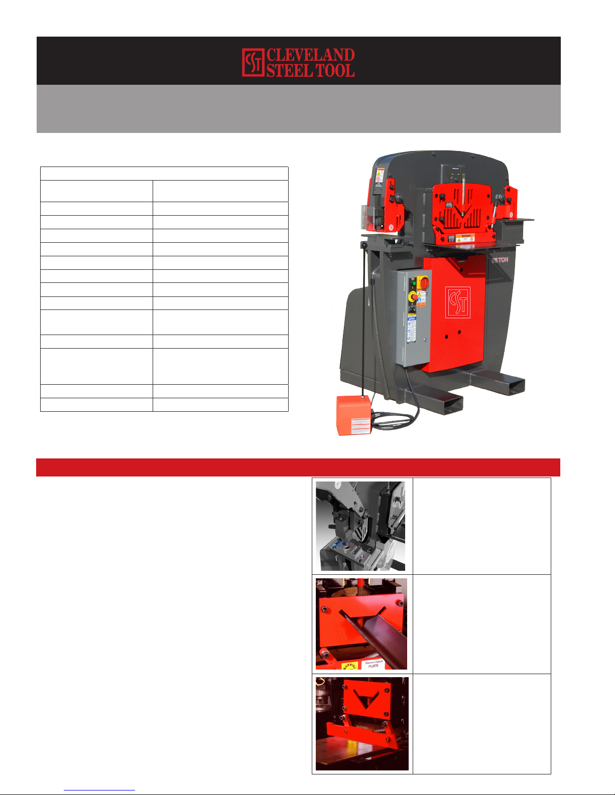
55 Ton Ironworker
STANDARD FEATURES
Technical Specifications
Rated capacity
**Rated at 65,000 psi tensile strength
55 Ton
Number of work stations 4
Throat depth 7-1/2"
Maximum capacity 1-1/16" dia. thru 5/8" plate
Largest standard punch 1-1/16" punch
Open height 8-1/8"
Closed height 6-7/8"
Stroke 1-1/4"
Table size 6" x 10"
Hydraulic system 7 gallon reservoir
2,500 PSI, 2-1/2" cylinder
Standard motor 5 HP, 3 phase 208V or 230V - 14amp
Optional motors 5 HP, 3 Phase, 460V - 7 amp
5 HP, 3 Phase, 575V - 6 amp
5 HP, 1 Phase, 208 or 230V - 23 amp
Dimensions Base 44-3/8" W x 36-1/8" D x 55-1/4" H
Shipping Weight 2,480 lbs.
Punch Station with
pedestal die table
219 Punch and 413 Die
Angle Shear
3" x 3" x 3/8"
4" x 4" x 1/4"
mild Steel
Flat Bar Shear
3/8" x 14"
1/2" x 12"
3/4" x 4"
mild Steel
• Fully guarded
• Gauge table
• Adjustable steel strippers
• Fully charged hydraulic system
• Electric stroke control
• Shear blades reversible for extra long life
• Direct drive pump
• Open station for optional tooling
1
Company Profile
The Cleveland Steel Tool Company offers a full
line of high quality, low maintenance hydraulic
ironworking machines, associated tooling and
accessories that are used in the steel fabrication
industry. With proper operation, care, and
maintenance, your Cleveland Steel Tool Ironworker
will provide years of safe, trouble-free ironworking
service. Please take time to study this manual
carefully to fully understand Ironworker safety
procedures, set-up, operation, maintenance,
troubleshooting and warranty coverage prior
to putting the machine into production. Any
questions not answered within this manual can
be directed to The Cleveland Steel Tool Company
or visit www.clevelandsteeltool.com for more
information.
474 E. 105th St.
Cleveland, OH 44108
800-446-4402 ph
216-681-7009 fx
Machine Identification
Your Cleveland Steel Tool Ironworker has been
serialized for quality control, product traceability
and warranty enforcement. Please refer to the
aluminum identification tag with the engraved serial
number and electrical and power specifications
when ordering parts or filing a warranty claim.
Record the serial number on the front of this
manual for easy reference.
Warranty
The Cleveland Steel Tool Company will, within
one (1) year of date of purchase, replace F.O.B.
the factory, any goods, excluding punches,
dies, and/or blades, which are defective in
materials and workmanship provided that the
buyer returns the defective goods, freight
prepaid, to the seller, which shall be the buyer’s
sole and exclusive remedy for the defective
goods. Hydraulic and electrical components
are subject to their respective manufacturer’s
warranties. The Cleveland Steel Tool Company
will, within thirty (30) days of date of purchase,
replace F.O.B. the factory any punches, dies,
and/or blades that prove to be defective in
material and workmanship. Proof of purchase
date required.
This warranty does not apply to machines
and/or components which have been altered,
changed or modified in any way, or subjected
to abusive and abnormal use, inadequate
maintenance and lubrication, or subjected to
use beyond seller recommended capacities
and specifications. In no event shall seller be
liable for labor costs expended on such goods
or consequential damages. Seller shall not
be liable to the purchaser or any other person
for loss, downtime, or damage directly or
indirectly arising from the use of the goods or
from any other cause. No officer, employee,
or agent of seller is authorized to make any
oral representations or warranty of fitness or to
waive any of the foregoing terms of sale and
none shall be binding on seller.
Table of contents


