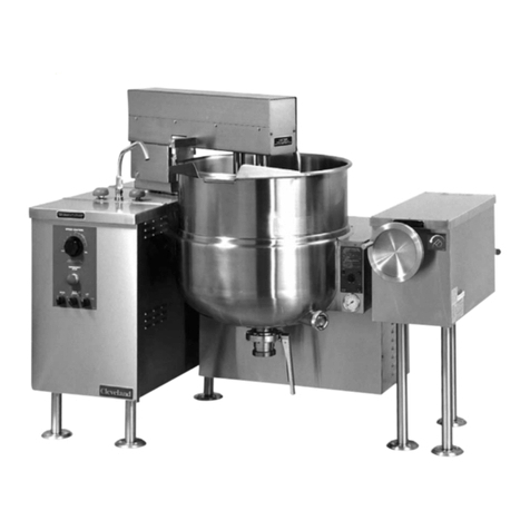
Cleveland KDM-T User manual

TABLE OF CONTENTS
Statement f Resp nsibilities . . . . . . . . . . . . . . . . . . . . . . . . . . . . . . . . . . . . . 1
F r y ur Safety . . . . . . . . . . . . . . . . . . . . . . . . . . . . . . . . . . . . . . . . . . . . . . . . . . . 2
Installati n . . . . . . . . . . . . . . . . . . . . . . . . . . . . . . . . . . . . . . . . . . . . . . . . . . . . . . . 4
Operating Instructi ns . . . . . . . . . . . . . . . . . . . . . . . . . . . . . . . . . . . . . . . . . . . . 6
Cleaning Instructi ns . . . . . . . . . . . . . . . . . . . . . . . . . . . . . . . . . . . . . . . . . . . . . 7
Preventative Maintenance . . . . . . . . . . . . . . . . . . . . . . . . . . . . . . . . . . . . . . . . 8
Maintenance . . . . . . . . . . . . . . . . . . . . . . . . . . . . . . . . . . . . . . . . . . . . . . . . . . . . . 9
Service Parts . . . . . . . . . . . . . . . . . . . . . . . . . . . . . . . . . . . . . . . . . . . . . . . . . . . . . 11
Read the manual thoroughl .
Improper installation, operation or
maintenance can cause propert
damage, injur or death.
!
For your future reference.
Model # ______________________________________
Serial # _______________________________________
Installation, Operation, Maintenance, Parts & Service
This manual is updated as new inf rmati n and m dels are released. Visit ur website f r the latest manual.
Modular Direct Steam
Kettles
Part # - KE004010-2 B August 2019
MODELS:
KDM-T
Model # &
Serial #.
Visit www.clevelandrange.c m t l cate a
service r sales representative in y ur area.

1.
STATEMENT OF RESPONSIBILITIES /
DÉCLARATION DES RESPONSABILITÉS /
DECLARACIÓN DE RESPONSABILIDADES
This document is for use by experienced
and trained Qualified Cleveland Range,
LLC Authorized Service Representatives
who are familiar with both the safety
procedures, and equipment they
service. Cleveland Range, LLC assumes
no liability for any death, injury,
equipment damage, or property damage
resulting from use of, improper use of,
or failure to use the information
contained in this document. Cleveland
Range, LLC has made every effort to
provide accurate information in this
document, but cannot guarantee that
this document does not contain
unintentional errors and omissions.
The information in this document may
be subject to technical and
technological changes, revisions, or
updates. Cleveland Range, LLC
assumes no liability or responsibility
regarding errata, changes, revisions, or
updates.
Qualified Cleveland Range, LLC
Authorized Service Representatives are
obligated to follow industry standard
safety procedures, including, but not
limited to, OSHA regulations, and
disconnect / lock out / tag out
procedures for all utilities including
steam, and disconnect / lock out / tag
out procedures for gas, electric, and
steam powered equipment and / or
appliances.
All utilities (gas, electric, water and
steam) should be turned OFF to the
equipment and locked out of operation
according to OSHA approved practices
during any servicing of Cleveland Range
equipment
Qualified Cleveland Range, LLC
Authorized Service Representatives are
obligated to maintain up-to-date
knowledge, skills, materials and
equipment.
Ce document est destiné à l’usage des
Représentants de Service qualifiés et
autorisés de Cleveland Range, LLC qui
possèdent l’expérience et la formation ainsi
que la bonne connaissance des mesures
de sécurité et du matériel qu’ils
entretiennent.
Cleveland Range, LLC décline toute
responsabilité pour tout cas de décès,
blessure, dommage matériel ou dommage
aux biens résultant de l'utilisation, de la
mauvaise utilisation ou du manquement
d’utilisation des renseignements contenus
dans ce document.
Cleveland Range, LLC s’est efforcé à
fournir des renseignements précis dans ce
document mais ne peut garantir que ce
document soit exempt d’erreurs et
d’omissions non intentionnelles.
Les renseignements contenus dans ce
document peuvent être assujettis à des
changements techniques et technologiques,
des révisions ou des mises à jour.
Cleveland Range, LLC décline toute
obligation ou responsabilité concernant les
errata, modifications, révisions ou mises à
jour.
Les Représentants de Service qualifiés et
autorisés de Cleveland Range, LLC sont
tenus de se conformer aux mesures de
sécurité normalisées de l’industrie, y
compris, mais sans s'y limiter, les
réglementations de l'OSHA, les procédures
de débranchement / verrouillage /
étiquetage relatives à tous les services
publics, dont l’approvisionnement en
vapeur, et les procédures de
débranchement / verrouillage / étiquetage
relatives aux équipements et/ou appareils
fonctionnant au gaz, à l’électricité et à la
vapeur.
Au cours de tout entretien d’un appareil
Cleveland Range, tous les services publics
(gaz, électricité, eau et vapeur) doivent être
FERMÉS au niveau de l’appareil et le
dispositif de fonctionnement doit être
verrouillé suivant les pratiques approuvées
de l’OSHA.
Les Représentants de Service qualifiés et
autorisés de Cleveland Range, LLC sont
tenus d’actualiser en permanence leurs
connaissances, compétences, matériel et
équipement.
Este documento está destinado para el uso
de los Representantes de Servicio
calificados y autorizados de Cleveland
Range, LLC quienes cuentan con la
experiencia y la capacitación así como el
buen conocimiento de las medidas de
seguridad y de los equipos que mantienen.
Cleveland Range, LLC, declina toda
responsabilidad en caso de cualquier
fallecimiento, lesiones, daños al equipo o
daños a la propiedad resultantes de la
utilización, del uso indebido o de la falta de
utilización de la información provista en este
documento.
Cleveland Range, LLC se ha esforzado en
suministrar información precisa en este
documento, pero no puede garantizar que
este documento esté exento de errores y de
omisiones no intencionales.
La información contenida en este
documento podría estar sujeta a cambios
técnicos o tecnológicos, revisiones o
actualizaciones. Cleveland Range, LLC
declina toda obligación o responsabilidad
con respecto a erratas, modificaciones,
revisiones o actualizaciones.
Los Representantes de Servicio calificados y
autorizados de Cleveland Range, LLC tienen
la obligación de seguir los procedimientos
estándar de seguridad de la industria; los
cuales incluyen pero no se limitan a los
reglamentos de la OSHA (La Administración
de la Seguridad y Salud Ocupacionales), los
procedimientos de desconexión, cierre y
etiquetado relativos a todos los servicios
públicos incluyendo el suministro de vapor y
los procedimientos de desconexión, cierre y
etiquetado para los equipos y/o aparatos
que funcionan a base de gas, electricidad o
vapor.
Cuando se esté dando servicio o
mantenimiento a un aparato de Cleveland
Range, todos los servicios públicos (gas,
electricidad, agua y vapor) deben estar
APAGADOS para el equipo en cuestión y se
debe seguir el procedimiento de cierre de
operaciones de acuerdo con las prácticas
aprobadas por la OSHA.
Los Representantes de Servicio calificados y
autorizados de Cleveland Range, LLC tienen
la obligación de actualizar constantemente
sus conocimientos, destrezas, materiales y
equipamiento.
2.
WARNING: Improper
installation, operation,
adjustment, alteration,
service or maintenance
can cause property
damage, injury or death.
Read the installation
and operating
instructions thoroughly
before installing,
operating or servicing
this equipment.
FOR YOUR SAFETY
Do not store or use
gasoline or any other
flammable liquids and
vapours in the vicinity of
this or any other
appliance.
Do not spray aerosols in the vicinity of
this appliance while it is in operation.
This appliance is not to be used by
persons with reduced physical,
sensory or mental capabilities, or lack
of experience and knowledge, unless
they have been given supervision or
instruction concerning use of the
appliance by a person responsible for
their safety.
This appliance is not for use by
children and they must be supervised
not to play with it.
Retain this manual for your reference.
AVERTISSEMENT : Toute
mauvaise pratique en matière
d’installation, de
fonctionnement, de réglage,
de modification, d’entretien ou
de maintenance peut causer
des dommages matériels, des
blessures ou la mort. Lisez la
totalité des instructions
d’installation et d’utilisation
avant d’installer, d’utiliser ou
d’entretenir cet équipement.
POUR VOTRE SÉCURITÉ
Ne pas entreposer ou
utiliser d'essence ou
d'autres liquides ou
vapeurs inflammables à
proximité de cet appareil
ou de tout autre appareil.
Ne pas pulvériser des aérosols dans le
voisinage de cet appareil alors qu'il est en
fonctionnement.
Cet appareil ne doit pas être utilisé par des
personnes dont les capacités physiques,
sensorielles ou mentales sont réduites, ou
des personnes dénuées d'expérience ou de
connaissance, sauf si elles ont pu bénéficier,
par l'intermédiaire d'une personne
responsable de leur sécurité, d'une
surveillance ou d'instructions préalables
concernant l'utilisation de l'appareil.
Cet appareil n'est pas destiné à être utilisé
par des enfants et ils doivent être surveillés
pour s'assurer qu'ils ne jouent pas avec
l'appareil.
Conservez ce manuel pour votre référence.
ADVERTENCIA: La indebida
instalación, operación,
ajuste, modificación,
servicio o mantenimiento
puede ocasionar daños a la
propiedad, lesiones o
muerte. Lea detenidamente
las instrucciones de
instalacion y de operación
antes de instalar, poner a
funcionar o dar servicio a
este equipo.
PARA SU SEGURIDAD
No guarde ni use gasolina
o cualesquiera otros
líquidos o vapores
inflamables en las
cercanías de éste o
cualquier otro aparato.
No pulverice aerosoles en las
proximidades de este aparato
mientras está en funcionamiento.
Este aparato no debe ser utilizado por
personas con capacidades físicas,
sensoriales o mentales reducidas, o
que no tengan la experiencia y los
conocimientos adecuados, a menos
que estas personas hayan recibido
supervisión e instrucciones en cuanto
al uso del aparato por la persona
responsable de la seguridad de ellas.
Guarde este manual para su
referencia.
FOR YOUR SAFETY / POUR VOTRE SÉCURITÉ /
PARA SU SEGURIDAD

3.
Improper installation, operation, adjustment, alteration,
service or maintenance can cause property damage,
injury or death. Read the installation and operating
instructions thoroughly before installing, operating or
servicing this equipment. / Toute mauvaise pratique en
matière d’installation, de fonctionnement, de réglage, de
modification, d’entretien ou de maintenance peut causer des dommages
matériels, des blessures ou la mort. Lisez la totalité des instructions
d’installation et d’utilisation avant d’installer, d’utiliser ou d’entretenir cet
équipement. / La indebida instalación, operación, ajuste, modificación,
servicio o mantenimiento puede ocasionar daños a la propiedad, lesiones o
muerte. Lea detenidamente las instrucciones de instalacion y de operación
antes de instalar, poner a funcionar o dar servicio a este equipo.
Surfaces and product may be hot! ear protective
equipment. /Les surfaces et le produit peuvent être
chauds! Portez un équipement de protection. / ¡Las
superficies y el producto pueden estar calientes!
Utilice equipo protector.
Stand clear of product discharge path
when discharging hot product. /
Écartez-vous du chemin de décharge
d’un produit chaud. / Permanezca
alejado de la ruta de descarga del
producto al vaciar producto caliente.
Keep hands away from moving parts and pinch points.
/ Gardez les mains loin des pièces mobiles et des
points de pincement. / Mantenga las manos lejos de
piezas movibles y puntos de presión muy localizada.
Hot product and surfaces. / Produit et
surfaces chaudes. / Producto y
superficies calientes.
Do not touch. / Ne pas toucher. / No
la toque
Do not climb, sit or stand on equipment. / Il ne faut pas
monter, s'asseoir ni se tenir debout sur l'équipement. /
No subirse, ni sentarse ni pararse sobre el equipo.
Pressurized device. / Appareil sous pression. /
Dispositivo de presión.
Keep clear of pressure relief discharge. / Restez à
l'écart de la soupape de sureté. / Permanezca alejado
de la descarga de presión.
Do not lean on or place objects on lip. / Ne vous
penchez pas sur oune placez pas des objets sur la
lèvre. / No se apoye ni coloque objetos en el labio.
Inspect unit daily for proper operation. / Inspectez
l’unité tous les jours pour son bon fonctionnement. /
Inspeccione diariamente el funcionamiento correcto de
la unidad.
Have a qualified service technician maintain your
equipment. / Demandez à un technicien en entretien
et en réparation qualifié d’effectuer l’entretien de votre
équipement. / Haga que un técnico de servicio
calificado mantenga su equipo
Floor may become slippery from product spillage. /
Déversement de produit peut causer de plancher à
être glissante. / Derrame de producto puede causar
piso a ser resbaladizo.
Do not fill kettle above recommended level marked on
outside of kettle. / Ne remplissez pas la chaudière en
excès du niveau recommandé marqué sur la
chaudière. / No llene la marmita arriba del nivel
recomendado marcado fuera de la marmita.
Unit must be anchored as per manual. / Unité doit être
ancrée selon les directives du manuel. / Unidad debe
estar fijado según el manual.
Heavy / Lourd / Pesado
Team or mechanical lift. / Équipe ou remontée
mécanique. / Equipo o elevador mecánico.
0
Ensure kettle is at room temperature and pressure
gauge is showing zero or less prior to removing any
fittings. / Assurez-vous que la chaudière est à
température ambiante et que le manomètre est à zéro
ou moins avant de retirer des accessoires. /
Asegúrese de que la marmita esté a temperatura
ambiente y el manómetro esté mostrando cero o
menos antes de retirar cualquier accesorio.
SERVICING / ENTRETIEN / SERVICIO
WARNING / AVERTISSEMENT / ADVERTENCIA
!
Remove electrical power prior to servicing. / Coupez
l'alimentation électrique avant l'entretien. / Desconecte
la energía eléctrica antes de darle servicio.
Risk of electric shock. / Risque de choc électrique. /
Riesgo de choque eléctrico.

4.
GENERAL
Installation of the unit must be accomplished by qualified
installation personnel working to all applicable local and
national codes. Improper installation of product could cause
injury or damage.
This unit is built to comply with applicable standards for
manufacturers. Included among those approval agencies
are: UL, NSF, ASME/Ntl.Bd., CSA, ETL, CE, and others.
Many local codes exist, and it is the responsibility of the
owner/installer to comply with these codes.
RECEIVING INS ECTION
Before uncrating, visually inspect the unit for evidence of
damage during shipping.
If damage is noticed, do not unpack the unit, follow
shipping damage instructions.
SHI ING DAMAGE
INSTRUCTIONS
If shipping damage to the unit is discovered or
suspected, observe the following guidelines in preparing
a shipping damage claim.
1. Write down a description of the damage or the reason
for suspecting damage as soon as it is discovered.
This will help in filling out the claim forms later. If
possible, take a polaroid picture.
2. As soon as damage is discovered or suspected, notify
the carrier that delivered the shipment.
3. Arrange for the carrier's representative to examine the
damage.
4. Fill out all carrier claims forms and have the
examining carrier sign and date each form.
APPROXIMATE WEIGHTS
UNCRATING
Caution:
Straps under tension and will snap when cut.
Carton may contain staples and Skid contains Nails.
Use proper safety equipment and precautions.
Unit is heavy use adequate help or lifting equipment as
needed.
1. Carefully cut any straps from container.
2. Lift off carton.
3. Inspect for hidden damage. If found refer to
“SHIPPING DAMAGE INSTRUCTIONS”.
4. Cut strap holding unit.
5. Remove manual from kettle pot. Write down
the model
# and serial#
of the unit onto the front of this manual.
6. Lift kettle off skid and move kettle to its installation
location.
7. Discard packaging material according to local and or
state requirements.
VENTILATION
Operation of these units can produce significant levels of steam
and condensate, it is recommended they be installed under a
ventilation hood in a room which has provisions for
adequate make up air. Further information can be
obtained by referring to the U.S.A. National Fire Protection
Associations NFPA96 regulations. These standards have
also been adopted by the National Building Code in
Canada.
INSTALLATION
Model # Unit Unit with
shipping box
KDM-25-T 330 lbs. 370 lbs.
KDM-40-T 385 lbs. 425 lbs.
KDM-60-T 430 lbs. 470 lbs.

5.
OSTITIONING
Position the kettle in its permanent location, and level
the kettle by turning the adjustable flanged feet. Once
positioned and levelled, permanently secure the kettle's
flanged feet to the floor using lag bolts and floor
anchors (to be supplied by the installer).
SERVICE CONNECTIONS
Install service connections as required. Locations and
other data are shown on the Specification Sheet.
FOR OWER TILT UNITS ONLY
NOTE: Ensure the electrical supply matches the kettle's
requirements as stated on the rating label.
This kettle is built to comply with CE standards. Many local
codes exist, and it is the responsibility of the owner and
installer to comply with these codes.
STEAM
All steam plumbing to and from the kettle and steam
boiler should be thoroughly cleaned and inspected for
dirt and debris before final connection to the kettle are
made.
Check the rating plate for the maximum steam pressure
that your kettle is rated for. If the steam supply pressure
exceeds the rated pressure, a pressure reducing valve
is required. The steam inlet is at the right side of the
kettle, as seen from the front.
CONDENSATE
A steam condensate trap must be plumbed to a drain,
using minimum 1/2" NPT plumbing. The condensate line is
limited to a maximum rise of 10 feet in order for the steam
pressure to adequately force the condensate through the
plumbing. Any higher rise requires a pump.
If the steam boiler to which this kettle is installed has a
condensate return (closed loop system), a 1/2" steam
strainer, a 1/2" steam trap, and a 1/2" check valve must be
installed on the output (condensate) side of the kettle.
OTABLE WATER
The water faucet (optional) with swing spout, requires 1/2
inch O.D. copper tube plumbing for hot or cold water
supplies to the faucet (SPK - cold water connection only,
DPK - hot and cold water connection).
INSTALLATION CHECK
1. Partially fill the kettle with water.
2. Slowly turn the steam supply valve's knob to the
open position.
3. Release the safety valve, ensuring that the steam
escapes freely. Stay clear of steam exhaust when
releasing the safety valve.
4. Observe that the water in the kettle comes to a
boil.
5. Close the steam supply valve.
6. Drain off the water in the kettle.
CLEANING
After installation the kettle must be thoroughly cleaned
ABCD
1Steam In
2To Drain or Boiler
Condensate Line
AStrainer
BUnion
CPressure Reducing
Valve
DShut Off Valve
STEAM REQUIREMENTS
Kettle Cap. Kettle 25 psi Steam
U.S. Gal. Dia. Lbs./Hr.
25 21" 70
40 26" 100
60 29.5" 150
pSteam requirements are maximum per hour.
pIf more than one unit is on the same line then add the
steam usage for each one to reach a total.
RECOMMENDED
I ING
SCHEMATICS
(all service connections
shown supplied by others)

6.
OPERATING
INSTRUCTIONS
# DESCRI TION
1. Steam Inlet Valve
Opens and closes the steam supply to the kettle.
2. Power Tilt Switch
Used for tilting the kettle up or down.
3. Drain Cock
Used to drain condensate from the bottom of tilting
units only.
4. Tangent Draw-Off Valve
Used for draining product or wash water from kettle.
5. Pressure Relief Valve (not shown)
In the unlikely event that there is an excess steam
build-up in the jacket, this valve automatically opens
to relieve this pressure.
O ERATION
1. Ensure that there is an adequate steam supply to the
kettle.
2. For optimum performance on free-standing floor model
tilting kettles, open drain cock to drain condensate
from the kettle’s jacket, then close drain cock before
applying steam to a cold kettle.
3. If the kettle is equipped with a tangent draw-off valve,
ensure that it is closed before filling the kettle. To keep
solid food particles out of the draw-off valve, place
either a solid or a perforated strainer in the bottom of
the kettle.
4. Turn the steam control valve to the
open position by turning the knob counter-
clockwise, then allow the kettle to preheat.
NOTE: When cooking egg and milk products, the kettle
should NOT be preheated, as products of this nature
adhere to hot cooking surfaces. These types of foods
should be placed in the kettle before heating is begun.
5. Fill kettle with product to desired level.
6. When the product has reached the
desired temperature, regulate the heat, as
required, by turning the steam control
valve clockwise for less steam, and
therefore, a lower temperature.
7. When cooking is complete, close the
steam control valve by turning the knob
clockwise.
8. Power tilt kettles are provided with a rocker-type
center-off switch for raising and lowering the kettle. To
raise the kettle, press the top of the switch. To lower
the kettle, press the bottom of the switch. Release the
switch, allowing it to return to the center “off” position
when the desired degree of tilt has been reached.
Limit switches are provided that automatically stop the
tilt motion at the maximum limit of movement in either
direction.
To raise and lower a manual tilt kettle, turn the
handwheel counter-clockwise to lower and clockwise
to raise.
FOR KETTLE/STEAMER COMBINATIONS:
If the boiler in a steamer is supplying steam to a kettle,
always heat the kettle first. After the kettle contents are
heated, and the boiler's steam pressure returns to normal,
the steamer may be used. Pressure steamer compartments
should be sequentially started, and preheated before
cooking.
2
43
1
WARNING
If for any reason this unit is
not functioning correctly
DO NOT OPERATE.
Contact your autorized
service agent.
!

7.
CARE AND CLEANING
Cooking equipment must be cleaned
regularly to maintain its fast, efficient
cooking performance and to ensure its
continued safe, reliable operation. The
best time to clean is shortly after each
use (allow unit to cool to a safe
temperature).
WARNINGS
Do not use
detergents or
cleansers that are
chloride based or
contain quaternary
salt.
Unit should never be
cleaned with a high
pressure spray hose.
Steel wool should
never be used for
cleaning the stainless
steel.
Do not leave water
sitting in unit when
not in use.
Do not use a metal
bristle brush or
scraper.
CLEANING INSTRUCTIONS
1. Turn unit off.
2. Remove drain screen (if applicable). Thoroughly wash and rinse the
screen either in a sink or a dishwasher.
3. Prepare a warm water and mild detergent solution in the unit.
4. Remove food soil using a nylon brush.
5. Loosen food which is stuck by allowing it to soak at a low temperature
setting.
6. Drain unit.
7. Rinse interior thoroughly.
8. If the unit is equipped with a Tangent Draw-Off Valve, clean as follows:
a) Disassemble the draw-off valve first by turning the valve knob
counter-clockwise, then turning the large hex nut counter-clockwise
until the valve stem is free of the valve body.
b) In a sink, wash and rinse the inside of the valve body using a nylon
brush.
c)
Use a nylon brush to clean tangent draw-off tube.
d) Rinse with fresh water.
e) Reassemble the draw-off valve by reversing the procedure for
disassembly. The valve's hex nut should be hand tight only.
9. Using mild soapy water and a damp sponge, wash the exterior, rinse,
and dry.
NOTES
➩For more difficult cleaning applications one of the following can be used:
alcohol, baking soda, vinegar, or a solution of ammonia in water.
➩Leave the cover off when the kettle is not in use.
➩For more detailed instructions refer to Stainless Steel Equipment Care
and Cleaning (www.nafem.org/resources/stainlesssteelfinal.doc) on
Nafem’s website (www.nafem.org).
Chloride Cleaners
Wire Brush &
Scrapers
Steel Pads
High Pressure
Spray Hose
Stagnant
Water
DIS OSAL INSTRUCTIONS
This unit is recyclable. Do not dispose in landfill.
The majority of the unit is composed of stainless steel.
Other alloys and electrical components make up a small
percentage of the total. Follow Federal, state and local
regulations for disposal.

8.
DAILY
RE-STARTU
INS ECTION
1. Steam valve opens and closes.
2. Product discharge valve is functioning correctly.
3. Cover opens and closes correctly and is not loose or damaged.
PREVENTATIVE MAINTENANCE
FOR MAINTENANCE AND REPAIRS CONTACT YOUR AUTHORI ED
MANITOWOC SERVICE AGENCY AND HAVE A QUALIFIED SERVICE
TECHNICIAN MAINTAIN YOUR EQUIPMENT.
SIX MONTH SERVICE INS ECTION
1 Perform daily startup inspection.
2. Test pressure relief valve.
3 Hand tilting - Check handwheel for tightness. If loose tighten Allen screw.
Power tilting - Check that kettle tilts smoothly. Grease as described in Lubrication Procedure.
4. Inspect for steam leaks inside and outside console.
5. Unit is bolted to the floor correctly.
6. Clean strainers.
Refer to maintenance procedurees and parts list manual
for detailed maintenance and testing instructions.
WARNING
If for any reason this unit is not functioning correctly DO NOT OPERATE.
Contact your autorized service agent.
!

9.
RESSURE RELIEF
VALVE TESTING
ROCEDURE
The pressure relief valve must be
checked at least twice a year as part
of the normal maintenance performed.
1. With the kettle empty, fully open the steam valve and
allow the kettle to preheat.
2.
Stand to the side of the pressure relief valve discharge tube and
pull valve open for a maximum of one second. Repeat test three
to four times. Each time the mechanism should
move freely and
be accompanied by a rapid escape of steam.
Þ
If valve appears to be sticking replace pressure relief valve.
ÞIf foreign material is discharged then drain kettle and
replace pressure relief valve.
STEAM TRA
To remove condensate that forms inside the steam jacket,
each kettle should be equipped with a steam trap in the line of
the kettle outlet to the drain. A good steam trap at startup
releases air and wet steam into the drain line for a few minutes,
then holds the steam in the jacket. During cooking, the trap
periodically releases accumulated condensate. If the kettle's
cooking performance becomes inadequate after long use,
replacement of the steam trap with a new one may restore
kettle operation to peak efficiency.
DRAW-OFF VALVE
To correct a leak at the draw-off valve, the source of the leak
must first be determined, Leaks from around the valve stem are
corrected by simply replacing the “O” ring. Faulty seating of the
valve stem disc against the valve body may cause dripping from
the valve even when the valve is tightly closed. This can often
be corrected by cleaning any residue from the disc and seat.
MAINTENANCE
ALL SERVICE MUST BE PERFORMED BY A QUALIFIED SERVICE TECHNICIAN.
This kettle requires very little preventative maintenance other than daily cleaning.
The pressure relief valve must be tested twice a year.
HINGE
ADJUSTMENT
INSTRUCTIONS
1. Insert 3/8" Allen wrench.
2. Turn clockwise to relieve tension on spring.
3. While tension is released remove one of the two
slotted screws.
4. To prevent Allen wrench from springing back abruptly
while the second slotted screw is removed, insert a pin
(approximately 1/8") in the hole where the first slotted
screw was removed from.
5. Remove second slotted screw.
6. While holding Allen wrench remove pin.
7. Turn Allen wrench clockwise to tighten or counter-
clockwise to loosen tension to produce desired effect.
8. Re-insert pin in one of the two holes.
9. Tighten one slotted screw in the other hole (it may be
necessary to turn Allen wrench slightly to align holes).
10. Remove pin and repeat step number 9. for other
slotted screw.
3/8" Allen
Wrench
WARNING
If for any reason this unit is not functioning correctly DO NOT OPERATE.
Contact your autorized service agent.
!

10.
WIRING DIAGRAM
Power Tilt Units Only
115 Volts, 1PH, 60HZ
120V
N L1
OFF
DOWNUP
JACK MOTOR
WHITE
RED
BLACK
MOTOR START CAPACITOR
SELECTOR SWITCH
TROUBLESHOOTING GUIDE
This section contains information intended for use by Authorized Service Personnel only.
A/ PROBLEM: Kettle heats too slowly or oes not come to a boil.
robable Cause Remedy
1. Inadequate steam flow. Check for correct steam.
If kettle is connected to a steamer and powered by a
generator the units should be operated sequentially (kettle boiling first, then start steamer).
2. Steam trap not operating properly. The trap should open periodically to dump condensate, then close.
If it does not open or close it should be cleaned or replaced.
3. Food batches are not always When checking make certain that the original state (ie. fresh or frozen)
the same. and quantity of food product is the same.
B/ PROBLEM: Kettle fails to tilt. (NOTE: A thermal overloa in jack motor oes not allow constant consecutive tilting.
robable Cause Remedy
1. Defective tilt switch. Shut off power to unit and remove entire control housing cover box to expose tilt
switch. Test switch for proper continuity. Replace if necessary.
2. Defective jack or capacitor. Remove cover from upper junction box. This will access the wire connections to
the power jack. Measure the resistance across each of the three wires. It is not
necessary to disconnect the wiring if proper contact can be made between
the probe and connectors. Their resistance should read (approximately):
14 ohms between the black and white,
29 ohms between the black and red, and
14 ohms between the red and white.
C/ PROBLEM: Kettle fails to lift or tilt at a normal spee .
robable Cause Remedy
1. Defective jack or capacitor. Shut off power to unit and remove entire control housing cover box to expose tilt
switch. Test switch for proper continuity. Replace if necessary..
D/ PROBLEM: The trunnion housing leaks steam.
robable Cause Remedy
1. Trunnion "O" rings are worn. Replace "O" rings
E/ PROBLEM: The steam trap makes a banging noise when steam applie to col kettle.
robable Cause Remedy
1. Kettle condensate has not On all tilting models the condensate should be drained when kettle is cold
been drained. using the drain cock valve on the bottom of the kettle.
STEAM REQUIREMENTS
Kettle Cap. Kettle 25 psi Steam
U.S. Gal. Dia. Lbs./Hr.
25 21" 70
40 26" 100
60 29.5" 150
pSteam requirements are maximum per hour.
p
If more than one unit is on the same line then add
the steam usage for each one to reach a total.

11.
KETTLE BODY
SERVICE PARTS
WARRANTY
Our Company supports a worldwide network of Maintenance and Repair Centers. Contact your nearest Maintenance and Repair
Centre for replacement parts, service, or information regarding the proper maintenance and repair of your cooking equipment
In order to preserve the various agency safety certification (UL, NSF, ASME/Ntl. Bd., etc.), only factory-supplied replacement
parts should be used. The use of other than factory supplied replacement parts will void warranty.

12.
PARTS LIST - KETTLE BODY
ITEM NO. PART NO. DESCRIPTION QTY.
1. KE50151-1 Knob, ball type . . . . . . . . . . . . . . . . . . . . . . . . . . . . . . . . . . . . . . . . . . . . . . . . . .1
2. T40294 Hose, Condensate (KDM-25) . . . . . . . . . . . . . . . . . . . . . . . . . . . . . . . . . . . . . . .1
T40295 Hose, Condensate (KDM-40, KDM-60) . . . . . . . . . . . . . . . . . . . . . . . . . . . . . . .1
5. F105028 Swivel Elbow, 1/2" . . . . . . . . . . . . . . . . . . . . . . . . . . . . . . . . . . . . . . . . . . . . . . . .2
6. KE51248-1 Steam Trap, 1/2" . . . . . . . . . . . . . . . . . . . . . . . . . . . . . . . . . . . . . . . . . . . . . . . . .1
7. KE02211-1 Left Door Hinge Bracket Assy. (used after une 02, 2000) . . . . . . . . . . . . . . . .1
KE00652 Left Door Hinge Bracket Assy. (used prior to une 02, 2000) . . . . . . . . . . . . . .1
8. KE02210-1 Left Door Assy. (KDM-25) . . . . . . . . . . . . . . . . . . . . . . . . . . . . . . . . . . . . . . . . . .1
KE02210-3 Left Door Assy. (KDM-40, KDM-60) . . . . . . . . . . . . . . . . . . . . . . . . . . . . . . . . . .1
9. KE02210-2 Right Door Assy. (KDM-25) . . . . . . . . . . . . . . . . . . . . . . . . . . . . . . . . . . . . . . . . .1
KE02210-4 Right Door Assy.(KDM-40,KDM-60) . . . . . . . . . . . . . . . . . . . . . . . . . . . . . . . . . .1
10. KE02211-2 Right Door Hinge Bracket Assy. (used after une 02, 2000) . . . . . . . . . . . . . . .1
KE00651 Right Door Hinge Bracket Assy. (used prior to une 02, 2000) . . . . . . . . . . . . .1
11. KE51340 Leg . . . . . . . . . . . . . . . . . . . . . . . . . . . . . . . . . . . . . . . . . . . . . . . . . . . . . . . . . . .4
12. KE00665 Swing Funnel Assy. (KDM-25) . . . . . . . . . . . . . . . . . . . . . . . . . . . . . . . . . . . . . .1
KE00666 Swing Funnel Assy. (KDM-40) . . . . . . . . . . . . . . . . . . . . . . . . . . . . . . . . . . . . . .1
KE00667 Swing Funnel Assy. (KDM-60) . . . . . . . . . . . . . . . . . . . . . . . . . . . . . . . . . . . . . .1
13. KE51365 Roller Wheel, 3” Dia. . . . . . . . . . . . . . . . . . . . . . . . . . . . . . . . . . . . . . . . . . . . . . .1
14. KE51683 Capacitor, 36-43 mF . . . . . . . . . . . . . . . . . . . . . . . . . . . . . . . . . . . . . . . . . . . . . .1
15. FA15010 Shoulder Bolt, 1/2" X 3 1/4", 3/8-16 . . . . . . . . . . . . . . . . . . . . . . . . . . . . . . . . . . .1
16. FA15009 Shoulder Bolt, 3/4" X 2 1/2", 5/8-11 . . . . . . . . . . . . . . . . . . . . . . . . . . . . . . . . . . .1
17. SK50680 Tilt Switch . . . . . . . . . . . . . . . . . . . . . . . . . . . . . . . . . . . . . . . . . . . . . . . . . . . . . .1
18 KE51688 Power ack, c/w Motor . . . . . . . . . . . . . . . . . . . . . . . . . . . . . . . . . . . . . . . . . . . .1
19. SE50025 Motor, Power ack . . . . . . . . . . . . . . . . . . . . . . . . . . . . . . . . . . . . . . . . . . . . . . . .1
20. KE51366-1 Magnetic Door Latch (used after October 11, 2001) . . . . . . . . . . . . . . . . . . . . .1
KE51366 Magnetic Door Latch (used prior to October 11, 2001) . . . . . . . . . . . . . . . . . . .1
21. KE00648 Drain Pipe Manifold . . . . . . . . . . . . . . . . . . . . . . . . . . . . . . . . . . . . . . . . . . . . . . .1
22. FI00040-2 Straight Elbow, 90, 1 1/2" . . . . . . . . . . . . . . . . . . . . . . . . . . . . . . . . . . . . . . . . . .1
23. F100191 End Cap, 1 1/2" . . . . . . . . . . . . . . . . . . . . . . . . . . . . . . . . . . . . . . . . . . . . . . . . . .1
24. KE51367 Check Valve, 1 1/4" . . . . . . . . . . . . . . . . . . . . . . . . . . . . . . . . . . . . . . . . . . . . . . .1
25. FI00136 Street Elbow, 90, 1 1/4" . . . . . . . . . . . . . . . . . . . . . . . . . . . . . . . . . . . . . . . . . . . .1
26. KE51372 Steam In Pipe 1/2" X 7 1/2" LG . . . . . . . . . . . . . . . . . . . . . . . . . . . . . . . . . . . . . .1
27. FI00040-1 Straight Elbow, 90, 1/2" . . . . . . . . . . . . . . . . . . . . . . . . . . . . . . . . . . . . . . . . . . . .1
28. KE51371 Steam In Pipe, 1/2" X 18 1/2" LG. . . . . . . . . . . . . . . . . . . . . . . . . . . . . . . . . . . . .1
29. KE54941-7 Safety Valve, 25 PSI, 1/2", ASME . . . . . . . . . . . . . . . . . . . . . . . . . . . . . . . . . . . .1
KE54941-32 Safety Valve, 25 PSI, 1/2", CE . . . . . . . . . . . . . . . . . . . . . . . . . . . . . . . . . . . . . . .1
30 KE02055-1 Steam Inlet Valve Assy. l/2" Brass . . . . . . . . . . . . . . . . . . . . . . . . . . . . . . . . . . . .1
31. FA11091 Screw, Valve Knob, 8/32 X 3/8" SS . . . . . . . . . . . . . . . . . . . . . . . . . . . . . . . . . . .1
32. KE50442 Knob, Steam Inlet Valve . . . . . . . . . . . . . . . . . . . . . . . . . . . . . . . . . . . . . . . . . . .1
33. FI00169 Tee, 1/2" . . . . . . . . . . . . . . . . . . . . . . . . . . . . . . . . . . . . . . . . . . . . . . . . . . . . . . . .1
34. FA15008 Shoulder Bolt 5/8" X 3 1/4", 1/2-13 . . . . . . . . . . . . . . . . . . . . . . . . . . . . . . . . . . .1
35. FI00142 Street Elbow, 1/2" . . . . . . . . . . . . . . . . . . . . . . . . . . . . . . . . . . . . . . . . . . . . . . . .1
36. T40292 Hose, Steam (KDM-25) . . . . . . . . . . . . . . . . . . . . . . . . . . . . . . . . . . . . . . . . . . . .1
T40293 Hose, Steam (KDM-40, KDM-60) . . . . . . . . . . . . . . . . . . . . . . . . . . . . . . . . . . . .1
37. KE51364 ack Mounting Pin . . . . . . . . . . . . . . . . . . . . . . . . . . . . . . . . . . . . . . . . . . . . . . . .1
38. KE51087 Blow Down Pipe, 1/2" X 17"LG. . . . . . . . . . . . . . . . . . . . . . . . . . . . . . . . . . . . . . .1
39. KE51433-1 Bracket Block, Left Hand . . . . . . . . . . . . . . . . . . . . . . . . . . . . . . . . . . . . . . . . . .1
40. KE51433-2 Bracket Block, Right Hand . . . . . . . . . . . . . . . . . . . . . . . . . . . . . . . . . . . . . . . . .1

13.
ITEM NO. PART NO. DESCRIPTION QTY.
1. - 7. KE50219 1.5” DRAW-OFF ASSEMBLY . . . . . . . . . . . . . . . . . . . . . . . . . . . . . . . . . . . . . . . .1
KE50973 3” DRAW-OFF ASSEMBLY . . . . . . . . . . . . . . . . . . . . . . . . . . . . . . . . . . . . . . . . .1
1. SE50019 WING NUT, TD-1.5 . . . . . . . . . . . . . . . . . . . . . . . . . . . . . . . . . . . . . . . . . . . . . . .1
FA21501-1 ACCORN NUT, TD-3 . . . . . . . . . . . . . . . . . . . . . . . . . . . . . . . . . . . . . . . . . . . . . .1
FA11511-1 SCREW (CORRECTIONAL PACKAGE) . . . . . . . . . . . . . . . . . . . . . . . . . . . . . . . .1
FA30505-1 WASHER (CORRECTIONAL PACKAGE) . . . . . . . . . . . . . . . . . . . . . . . . . . . . . .1
2. SE50017 KNOB, TD-1.5 . . . . . . . . . . . . . . . . . . . . . . . . . . . . . . . . . . . . . . . . . . . . . . . . . . .1
SE50018 KNOB, TD-3 . . . . . . . . . . . . . . . . . . . . . . . . . . . . . . . . . . . . . . . . . . . . . . . . . . . .1
3. FI05180-3 HEX NUT, TD-1.5 . . . . . . . . . . . . . . . . . . . . . . . . . . . . . . . . . . . . . . . . . . . . . . . . .1
FI05180-2 HEX NUT, TD-3 . . . . . . . . . . . . . . . . . . . . . . . . . . . . . . . . . . . . . . . . . . . . . . . . . .1
4. SE50011 RETAINER, TD-1.5 . . . . . . . . . . . . . . . . . . . . . . . . . . . . . . . . . . . . . . . . . . . . . . . .1
SE50013 RETAINER, TD-3 . . . . . . . . . . . . . . . . . . . . . . . . . . . . . . . . . . . . . . . . . . . . . . . . .1
5. SE50008 PISTON, TD-1.5 . . . . . . . . . . . . . . . . . . . . . . . . . . . . . . . . . . . . . . . . . . . . . . . . . .1
SE50010-1 PISTON, TD-3 . . . . . . . . . . . . . . . . . . . . . . . . . . . . . . . . . . . . . . . . . . . . . . . . . . .1
KE53290-4 PISTON, TD-3, MODIFIED (CORRECTIONAL PACKAGE) . . . . . . . . . . . . . . . . .1
6. FA05002-24 "O" RING, TD-1.5 . . . . . . . . . . . . . . . . . . . . . . . . . . . . . . . . . . . . . . . . . . . . . . . . .1
FA05002-38 "O" RING, TD-3 . . . . . . . . . . . . . . . . . . . . . . . . . . . . . . . . . . . . . . . . . . . . . . . . . .1
7. SE50005 VALVE BODY, TD-1.5 . . . . . . . . . . . . . . . . . . . . . . . . . . . . . . . . . . . . . . . . . . . . .1
KE50973 VALVE BODY, TD-3 . . . . . . . . . . . . . . . . . . . . . . . . . . . . . . . . . . . . . . . . . . . . . .1
1
2
3
4
5
6
7
8
TANGENT DRAW-OFF VALVES
ITEM NO. PART NO. DESCRIPTION QTY.
1. - 7. KE50972-B 2” DRAW-OFF ASSEMBLY . . . . . . . . . . . . . . . . . . . . . . . . . . . . . . . . . . . . . . . . .1
1. FA95049 WING NUT, TD-2 . . . . . . . . . . . . . . . . . . . . . . . . . . . . . . . . . . . . . . . . . . . . . . . . .1
FA511511-5 SCREW, TD-2 (CORRECTIONAL PACKAGE) . . . . . . . . . . . . . . . . . . . . . . . . . . .1
2. KE52755 KNOB, TD-2 . . . . . . . . . . . . . . . . . . . . . . . . . . . . . . . . . . . . . . . . . . . . . . . . . . . .1
3. FI05180-1 HEX NUT, TD-2 . . . . . . . . . . . . . . . . . . . . . . . . . . . . . . . . . . . . . . . . . . . . . . . . . .1
4. KE52753 RETAINER, TD-2 . . . . . . . . . . . . . . . . . . . . . . . . . . . . . . . . . . . . . . . . . . . . . . . . .1
5. KE52752-1 PISTON, TD-2 . . . . . . . . . . . . . . . . . . . . . . . . . . . . . . . . . . . . . . . . . . . . . . . . . . .1
KE53290-3 PISTON, TD-2 (CORRECTIONAL PACKAGE) . . . . . . . . . . . . . . . . . . . . . . . . . . .1
6. FA05002-24 "O" RING, BUNA-N (A-111), TD-2 . . . . . . . . . . . . . . . . . . . . . . . . . . . . . . . . . . . .1
7. FA05002-55 "O" RING, VITON (AS568A-322), TD-2 . . . . . . . . . . . . . . . . . . . . . . . . . . . . . . .1
8. KE52751 VALVE BODY, TD-2 . . . . . . . . . . . . . . . . . . . . . . . . . . . . . . . . . . . . . . . . . . . . . . .1
TDV 09/14
1
2
3
4
5
6
7
1.5” & 3” TANGENT
DRAW-OFF VALVE
2” TANGENT DRAW-
OFF VALVE

14.
FAUCETS
Common Part
ITEM # PART # DESCRIPTION QTY.
SPK ____ SINGLE PANTRY FAUCET KIT, (includes items 1-10) see page 2 for ordering information
DPK ____ DOUBLE PANTRY FAUCET, (includes items 1-8 & 11) see page 2 for ordering information
1. KE50825- ___ SPOUT, see page 2 for ordering information
2. ____________ FAUCET MOUNTING BRACKET, see page 2 for ordering information . . . . . . . . . . . . . .1
3. FA05002-19 "O" RING . . . . . . . . . . . . . . . . . . . . . . . . . . . . . . . . . . . . . . . . . . . . . . . . . . . . . . . . . . . . . . .1
4. KE51736 LONG FAUCET NUT . . . . . . . . . . . . . . . . . . . . . . . . . . . . . . . . . . . . . . . . . . . . . . . . . . . . . .1
5. FA95007-10 RETAINING RING . . . . . . . . . . . . . . . . . . . . . . . . . . . . . . . . . . . . . . . . . . . . . . . . . . . . . . . .1
6. FA11258 HEX CAP SCREW . . . . . . . . . . . . . . . . . . . . . . . . . . . . . . . . . . . . . . . . . . . . . . . . . . . . . . . .2
7. FA31029 LOCK WASHER . . . . . . . . . . . . . . . . . . . . . . . . . . . . . . . . . . . . . . . . . . . . . . . . . . . . . . . . .2
8. FA21008 HEX NUT . . . . . . . . . . . . . . . . . . . . . . . . . . . . . . . . . . . . . . . . . . . . . . . . . . . . . . . . . . . . . . .2
9. KE51401 SINGLE PANTRY BODY (c/w item 13) . . . . . . . . . . . . . . . . . . . . . . . . . . . . . . . . . . . . . . . .1
10. KE50335 ADAPTER WASHER . . . . . . . . . . . . . . . . . . . . . . . . . . . . . . . . . . . . . . . . . . . . . . . . . . . . . .1
11. KE51403 DOUBLE PANTRY BODY (c/w item 13 & 14) . . . . . . . . . . . . . . . . . . . . . . . . . . . . . . . . . .1
12. SE50447 REPLACEMENT HORSESHOE WASHER . . . . . . . . . . . . . . . . . . . . . . . . . . . . . . . . . . . . . .1
13. SE50021 REPLACEMENT STEM ASSEMBLY, COLD WATER . . . . . . . . . . . . . . . . . . . . . . . . . . . . . .1
14. SE50020 REPLACEMENT STEM ASSEMBLY, HOT WATER . . . . . . . . . . . . . . . . . . . . . . . . . . . . . . . .1
15. SD50097 FLANGED NUT, 3/4" NPT, CHROME PLATED . . . . . . . . . . . . . . . . . . . . . . . . . . . . . . . . . .1
16. KE51585 FAUCET SPOUT FITTING . . . . . . . . . . . . . . . . . . . . . . . . . . . . . . . . . . . . . . . . . . . . . . . . . .1
17. SD50098 LOCKNUT, 3/4" NPT . . . . . . . . . . . . . . . . . . . . . . . . . . . . . . . . . . . . . . . . . . . . . . . . . . . . . .1
18. FI00266 COUPLING, 1/2" NPT . . . . . . . . . . . . . . . . . . . . . . . . . . . . . . . . . . . . . . . . . . . . . . . . . . . . .1
19. SD50100 COPPER TUBE . . . . . . . . . . . . . . . . . . . . . . . . . . . . . . . . . . . . . . . . . . . . . . . . . . . . . . . . . .1
20. KE51899 REMOTE VALVE (c/w item 13 & 14) . . . . . . . . . . . . . . . . . . . . . . . . . . . . . . . . . . . . . . . . .1
11
12
6
5
7
8
1
5
3
4
9
10
13
6
2
7
8
1314
1/2”
NPT
3/8”
COPPER
TUBE
15
16
17
18
19
14 13
20
Page 1 of 2

15.
Model
FAUCETS
FAUCET
KIT BRACKET SPOUT
KDT12/20 ON SD TABLE SPK1 KE50825-1
DPK1
KDL60/80/100T SPK2 KE54159 KE50825-2
KEL40/60/80/100T DPK2 KE02071-1 (CP)
KET20
KGT,MKET, KDP60-100/T
KDL25/40T SPK3 KE54159 KE50825-3
KEL25T,KDP25/40T DPK3
KDM60/T SPK-KDM60 KE50825-2
DPK-KDM60
KDM25/40/T SPK6 KE50825-6
DPK6
KDL40/60/80TSH SPK7 KE54159 KE50825-7
KEL40/60TSH DPK7
KDT6 ON SD OR ST SPK8 KE50825-8
DPK8
TKET, KET3/6/12 SPK9 KE54159 KE50825-9
DPK9
KDL125/150T SPK10 KE54159 KE50825-10
KGL40/60/80T DPK10
KGL40TSH
HAMKGL60/80/100T SPK11 KE54159 KE50825-11
DPK11
KGL25T, T1 SPK13 SK00395-1 KE50825-7
DPK13 KE02071-2 (CP)
TR SPK14 SK2382300 KE50825-6
DPK14 SK2382400 (SPACER)
SET10 DPK15 SK2308800 KE50825-6
SPK15
SET15 SPK16 SK2302200 KE50825-6
DPK16
HAMKGL60/80/100 DPK17 KE50825-12
SKP17
ALL STATIONARY KETTLES DPK5 KE50825-5
SPK5
Page 2 of 2

16.
KE00597
HINGE 05/14
HINGE ASSEMBLY
1
5
32
1312
8
4
7
11
6
10
9
9
-KE00597-6
-KE00597-4
-KE00597-2
-KE00597-1
ITEM PART #
DESCRIPTION
A
QTY QTY QTY QTY
1KE50822 HINGE BASE; CHS 1111
2 KE51217 HINGE CYLINDER 1111
3KE50121-1 HINGE SPRING; HEAVY (0.187DIA/12 COILS) -11-
KE50121-2 HINGE SPRING; LIGHT (0.162DIA/16 COILS) 1--1
4KE50823-1 HINGE PIN; LIGHT SPRING 1--1
KE50823-2 HINGE PIN MODIFD; HEAVY SPRING -11-
5KE50824 HINGE BEARING; MODIFIED 1111
6KE50819-1 HINGE END PIECE; LHS 11--
KE50819-2 HINGE END PIECE; LHS MODIFIED (TO 100 DEGREE) --11
7KE50820 HINGE INSERT; CHS 1111
8KE50819 HINGE END PIECE; RHS 1111
9
10. FA11507 Cutting Screw, 2 2 2 2
11. KE54907-10 Plug Button 1 1 1 1
12. KE50151-2 Knob 1 1 1 1
13. Cover Handle (specify model) 1 1 1 1
FA11284 SCREW; 1/4-20 X 1/2" HEX SOCKET 4444

+1 -80 0.3 38- 2 204 W WW. CLE VEL A NDR ANG E.C OM
KitchenCare
StarCare – Warranty & lifeme service, cerfied OEM parts, global parts inventory, performance audited
ExtraCare — CareCode, 24/7 Support, online/mobile product informaon
LifeCare – Install & equipment orientaon, planned maintenance, KitchenConnect™, MenuConnect®
Talk with KitchenCare® • 1-844-724-CARE • www.mtwkitchencare.com
To learn how Welbilt Foodservice and its leading brands can equip you, visit our global web site at
www.welbilt.com, then discover the regional or local resources available to you.
Every new piece of Welbilt Foodservice equipment comes with KitchenCare® and you choose the level of service that meets
your operaonal needs from one restaurant to mulple locaons
©2016 Welbilt Foodservice except where explicitly stated otherwise. All rights reserved. Connuing product improvement may necessitate change of specifiaons without noce.
Table of contents
Other Cleveland Commercial Food Equipment manuals

Cleveland
Cleveland T1 Electric Owner's manual

Cleveland
Cleveland KGL-60 User manual

Cleveland
Cleveland SGY-250 User manual

Cleveland
Cleveland KEL-25 User manual

Cleveland
Cleveland SteamChef 22CCT6 Instruction Manual

Cleveland
Cleveland KGM Operating instructions

Cleveland
Cleveland SGP Series User manual

Cleveland
Cleveland SPLASH PROOF SET-10 User manual

Cleveland
Cleveland SZ-4135 User manual

Cleveland
Cleveland AWC1 User manual