Clevertronics L10 LIFELIGHT PRO LLIFE-PRO-SMS-SPOT Installation and operating instructions

1942034
V1.2
3 March 2020
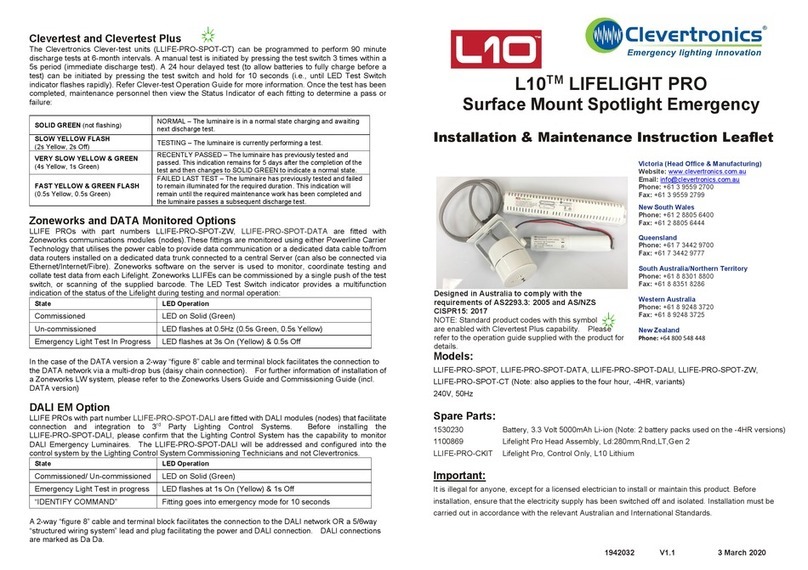
Clevertest and Clevertest Plus
The Clevertronics Clever-test units (LLIFE-PRO-SMS-SPOT-CT) can be programmed to perform 90
minute discharge tests at 6-month intervals. A manual test is initiated by pressing the test switch 3 times
within a 5s period (immediate discharge test). A 24 hour delayed test (to allow batteries to fully charge
before a test) can be initiated by pressing the test switch and hold for 10 seconds (i.e., until LED Test
Switch indicator flashes rapidly). Refer Clever-test Operation Guide for more information. Once the test
has been completed, maintenance personnel then view the Status Indicator of each fitting to determine a
pass or failure:
SOLID GREEN (not flashing) NORMAL – The luminaire is in a normal state charging and awaiting
next discharge test.
SLOW YELLOW FLASH
(2s Yellow, 2s Off)
TESTING – The luminaire is currently performing a test.
VERY SLOW YELLOW & GREEN
(4s Yellow, 1s Green)
RECENTLY PASSED – The luminaire has previously tested and
passed. This indication remains for 5 days after the completion of the
test and then changes to SOLID GREEN to indicate a normal state.
FAST YELLOW & GREEN FLASH
(0.5s Yellow, 0.5s Green)
FAILED LAST TEST – The luminaire has previously tested and failed
to remain illuminated for the required duration. This indication will
remain until the required maintenance work has been completed and
the luminaire passes a subsequent discharge test.
Zoneworks and DATA Monitored Options
LLIFE PROs with part numbers LLIFE-PRO-SMS-SPOT-ZW, LLIFE-PRO-SMS-SPOT-DATA are fitted
with Zoneworks communications modules (nodes).These fittings are monitored using either Powerline
Carrier Technology that utilises the power cable to provide data communication or a dedicated data cable
to/from data routers installed on a dedicated data trunk connected to a central Server (can also be
connected via Ethernet/Internet/Fibre). Zoneworks software on the server is used to monitor, coordinate
testing and collate test data from each Lifelight. Zoneworks LLIFEs can be commissioned by a single
push of the test switch, or scanning of the supplied barcode. The LED Test Switch indicator provides a
multifunction indication of the status of the Lifelight during testing and normal operation:
State
LED Operation
Commissioned LED on Solid (Green)
Un-commissioned LED flashes at 0.5Hz (0.5s Green, 0.5s Yellow)
Emergency Light Test In Progress LED flashes at 3s On (Yellow) & 0.5s Off
In the case of the DATA version a 2-way “figure 8” cable and terminal block facilitates the connection to
the DATA network via a multi-drop bus (daisy chain connection). For further information of installation of
a Zoneworks LW system, please refer to the Zoneworks Users Guide and Commissioning Guide (incl.
DATA version)
DALI EM Option
LLIFE PROs with part number LLIFE-PRO-SMS-SPOT-DALI are fitted with DALI modules (nodes) that
facilitate connection and integration to 3rd Party Lighting Control Systems. Before installing the
LLIFE-PRO-SMS-SPOT-DALI, please confirm that the Lighting Control System has the capability to
monitor DALI Emergency Luminaires. The LLIFE-PRO-SMS-SPOT-
DALI will be addressed and
configured into the control system by the Lighting Control System Commissioning Technicians and not
Clevertronics.
State
LED Operation
Commissioned/ Un-commissioned LED on Solid (Green)
Emergency Light Test in progress LED flashes at 1s On (Yellow) & 1s Off
“IDENTIFY COMMAND” Fitting goes into emergency mode for 10 seconds
A 2-way “figure 8” cable and terminal block facilitates the connection to the DALI network OR a 5/6way
“structured wiring system” lead and plug facilitating the power and DALI connection. DALI connections
are marked as Da Da.
L10™ LIFELIGHT PRO
Surface Mount Spotlight Emergency
Installation & Maintenance Instruction Leaflet
Models:
LLIFE
-PRO-SMS-SPOT, LLIFE-PRO-SMS-SPOT-DATA, LLIFE-PRO-SMS-SPOT-DALI,
LLIFE
-PRO-SMS-SPOT-ZW, LLIFE-PRO-SMS-SPOT-CT (Note: also applies to the four hour, -4HR,
variants)
240V, 50Hz
Spare Parts:
153
0230 Battery, 3.3 Volt 5000mAh Li-ion (Note: 2 battery packs used on the -4HR versions)
1100869
Lifelight Pro Head Assembly, Ld:280mm,Rnd,LT,Gen 2
LLIFE
-PRO-SMS-CKIT-NP LifelightPro,Control Only, L10, NP
Important
:
It is illegal for anyone, except for a licensed electrician to install or maintain this product. Before
installation, ensure that the electricity supply has
been switched off and isolated. Installation must be
carried out in accordance with the relevant Au
stralian and International Standards.
Designed in Australia to comply with the
requirements of AS2293.3: 2005 and AS/NZS
CISPR15: 2017
NOTE: Standard product codes with this symbol
are enabled with Clevertest Plus capability. Please
refer to the operation guide supplied with the product for
details.
Victoria (Head Office & Manufacturing)
Website:
www.clevertronics.com.au
Email:
info@clevertronics.com.au
Phone:
+61 3 9559 2700
Fax:
+61 3 9559 2799
New South Wales
Phone:
+61 2 8805 6400
Fax:
+61 2 8805 6444
Queensland
Phone:
+61 7 3442 9700
Fax:
+61 7 3442 9777
South Australia/Northern Territory
Phone:
+61 8 8301 8800
Fax:
+61 8 8351 8286
Western
Australia
Phone:
+61 8 9248 3720
Fax:
+61 8 9248 3725
New Zealand
Phone:
+64 800 548 448

1942034
V1.2
3 March 2020
Testing:
When the
LLIFE-PRO-SMS-SPOT unit is connected to the un-switched active, it must be allowed to
charge the battery for at least 24 hour
s. The emergency lamp only illuminates during a power fail.
Conduct the following tests:
•
The emergency lamp must illuminate for at least 2 hours after disconnection from the mains. The
results of all tests are required to be recorded in a service logbook, which is to be kept on-site at all
times. If the unit fails to illuminate for the requisite time, remedial action must be taken to repair the
situation and once completed, the unit must pass a subsequent test.
•
Press and hold Test Button or switch Off Mains Supply, check that the emergency lamp is On.
•
Release the Test Button or Switch On Mains Supply, check that the emergency lamp is Off
(Non-maintained operation).
Below are a list of common pro
blems and their possible causes:
Fault:
The Green LED indicator is not illuminated.
Check:
A.C. is connected and is turned on.
Battery is connected.
Test Switch for damage.
Fault:
Lamp does not illuminate in emergency mode.
Check:
A.C. is connected.
Lamp is correctly inserted.
Battery is connected
Fault:
Lamp illuminates in emergency mode, but only stays on for a short period.
Check:
Battery has been allowed to charge for at least 24 hours.
Battery for damage.
Rated Emergency Lumen Output
in accordance with AS2293.1 (refer to
spacing tables for installation positions)
:
N/A
Caution:
On many building sites, power circuits may be cut off in an uncontrolled and repetitive basi
s during
construction. As a result, any Lifelight Units, on these circuits, will have their batteries discharged or
“cycled”. The
Li-ion battery in the Lifelight has been selected to give excellent long life performance in a
controlled IEC 60598
-2-22 testing environment. Excessive battery cycling will reduce through-life
performance and may lead to premature battery failure. Battery warran
ty claims, as a result of such
abuse
, are specifically EXCLUDED from Clevertronics warranty terms.
Warranty:
For Product Warranty information and Terms and Conditions of Sales please refer to our website
http://clevertronics.com.au/terms
-conditions-sale-australia-nz/
Installation:
This
LLIFE-PRO-SMS-SPOT Surface Mount Non-maintained Emergency Luminaire can be installed
on solid or T
-BAR ceilings or used to replace an existing unit.
•
Locate the installation position.
•
Remove the top cover (containing the control gear) from the base plate via the two fixing screws
on the top cover. Disconnect the mains supply cable via the connector between the base and
top cover.
•
Refer Images and Dimensions below for the Cut-out Hole and other dimensions.
•
Pre-drill mounting holes.
•
Mount base plate and use suitable fixings to secure the base plate into the pilot holes.
•
Bring in supply cables via the rear entry hole or via the end of the base plate (surface mount
conduit entry).
•
Terminate the supply cables to the L, N & E terminals (in the case of the –DALI or –
DATA fittings
terminate the DALI or DATA cable to the terminals marked Da Da or DATA).
•
Install the top cover, containing the control gear, ensuring to reconnect the control gear assembly
to the connector from the supply terminal block.
•
Ensure the Battery is connected.
•
Screw the cover to the base plate, and in the case of side/conduit entry remove the knock-out at
the end of the cover to go cover the conduit.
Upgrading a
LLIFE-PRO to Clever-test, Zoneworks (incl. DATA) or
DALI EM
All
L10 Lifelight PRO Emergency Luminaires (LLIFE-PRO-SMS-SPOT) can be upgraded to
Clever
-test, Zoneworks, Zoneworks DATA or DALI EM.
When upgrading simply insert the relevant smart node board.
Unlike previous versions of product
DO NOT remove or alter the configuration of jumpers.
T
here is NO need to remove any jumper for the correct operation of the plugin node.
Mains entry hole
Images and Dimensions:
This manual suits for next models
4
Other Clevertronics Spotlight manuals
Popular Spotlight manuals by other brands
EuroLite
EuroLite LED FX Par-100 RGB user manual
Titanium
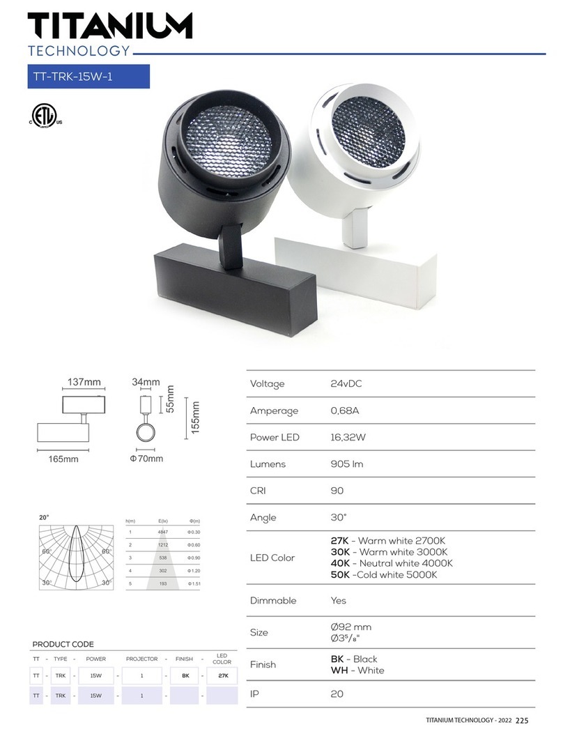
Titanium TT-TRK-15W-1 quick guide
Cooper
Cooper Invue ClearPath Bollard installation instructions
Portfolio
Portfolio FLBKS80101 manual
Brinkmann
Brinkmann 800-2200-B Owner's manual & operating instructions
Challenger
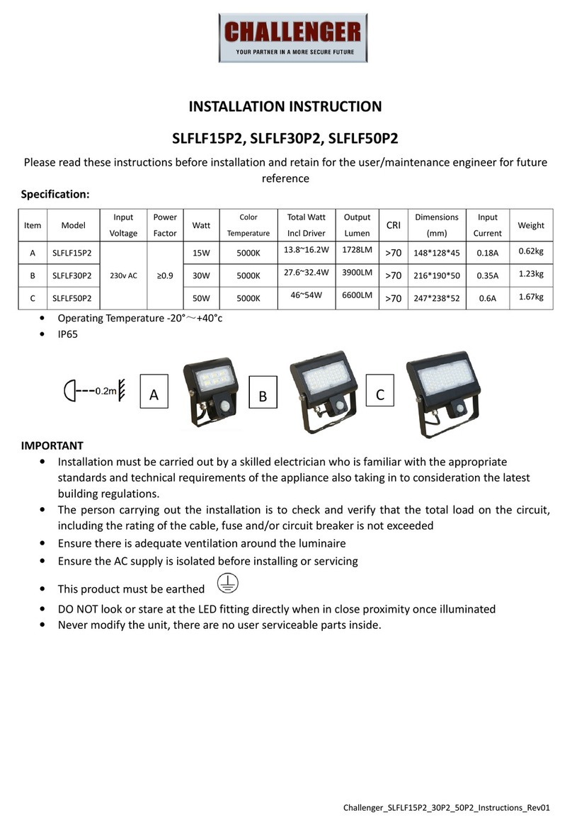
Challenger SLFLF15P2 Installation instruction

