Clevo M815L User manual


Preface
I
Preface
Notebook Computer
M815L/M816L
Service Manual

Preface
II
Preface
Notice
The company reserves the right to revise this publication or to change its contents without notice. Information contained
herein is for reference only and does not constitute a commitment on the part of the manufacturer or any subsequent ven-
dor. They assume no responsibility or liability for any errors or inaccuracies that may appear in this publication nor are
they in anyway responsible for any loss or damage resulting from the use (or misuse) of this publication.
This publication and any accompanying software may not, in whole or in part, be reproduced, translated, transmitted or
reduced to any machine readable form without prior consent from the vendor, manufacturer or creators of this publica-
tion, except for copies kept by the user for backup purposes.
Brand and product names mentioned in this publication may or may not be copyrights and/or registered trademarks of
their respective companies. They are mentioned for identification purposes only and are not intended as an endorsement
of that product or its manufacturer.
Version 1.0
August 2009
Trademarks
Intel and Atom are trademarks of Intel Corporation.
Windows®is a registered trademark of Microsoft Corporation.
Other brand and product names are trademarks and/or registered trademarks of their respective companies.

Preface
III
Preface
About this Manual
This manual is intended for service personnel who have completed sufficient training to undertake the maintenance and
inspection of personal computers.
It is organized to allow you to look up basic information for servicing and/or upgrading components of the M815L/
M816L series notebook PC.
The following information is included:
Chapter 1, Introduction, provides general information about the location of system elements and their specifications.
Chapter 2, Disassembly, provides step-by-step instructions for disassembling parts and subsystems and how to upgrade
elements of the system.
Appendix A, Part Lists
Appendix B, Schematic Diagrams

Preface
IV
Preface
IMPORTANT SAFETY INSTRUCTIONS
Follow basic safety precautions, including those listed below, to reduce the risk of fire, electric shock and injury to per-
sons when using any electrical equipment:
1. Do not use this product near water, for example near a bath tub, wash bowl, kitchen sink or laundry tub, in a wet
basement or near a swimming pool.
2. Avoid using a telephone (other than a cordless type) during an electrical storm. There may be a remote risk of elec-
trical shock from lightning.
3. Do not use the telephone to report a gas leak in the vicinity of the leak.
4. Use only the power cord and batteries indicated in this manual. Do not dispose of batteries in a fire. They may
explode. Check with local codes for possible special disposal instructions.
5. This product is intended to be supplied by a Listed Power Unit (Full Range AC/DC Adapter – AC Input 100 - 240V,
50 - 60Hz, DC Output 19V, 1.57A/1.58A).
This Computer’s Optical Device is a Laser Class 1 Product

Preface
V
Preface
Instructions for Care and Operation
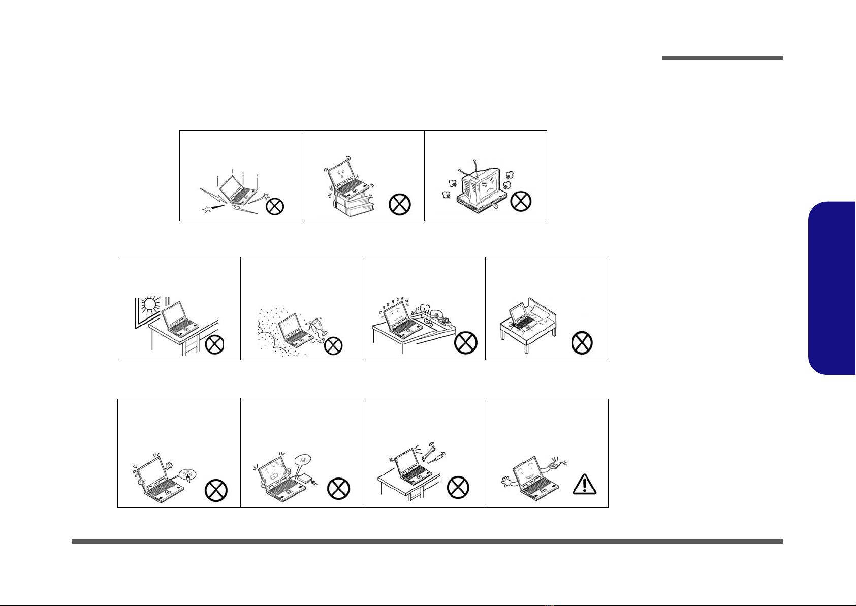
The notebook computer is quite rugged, but it can be damaged. To prevent this, follow these suggestions:
1. Don’t drop it, or expose it to shock. If the computer falls, the case and the components could be damaged.
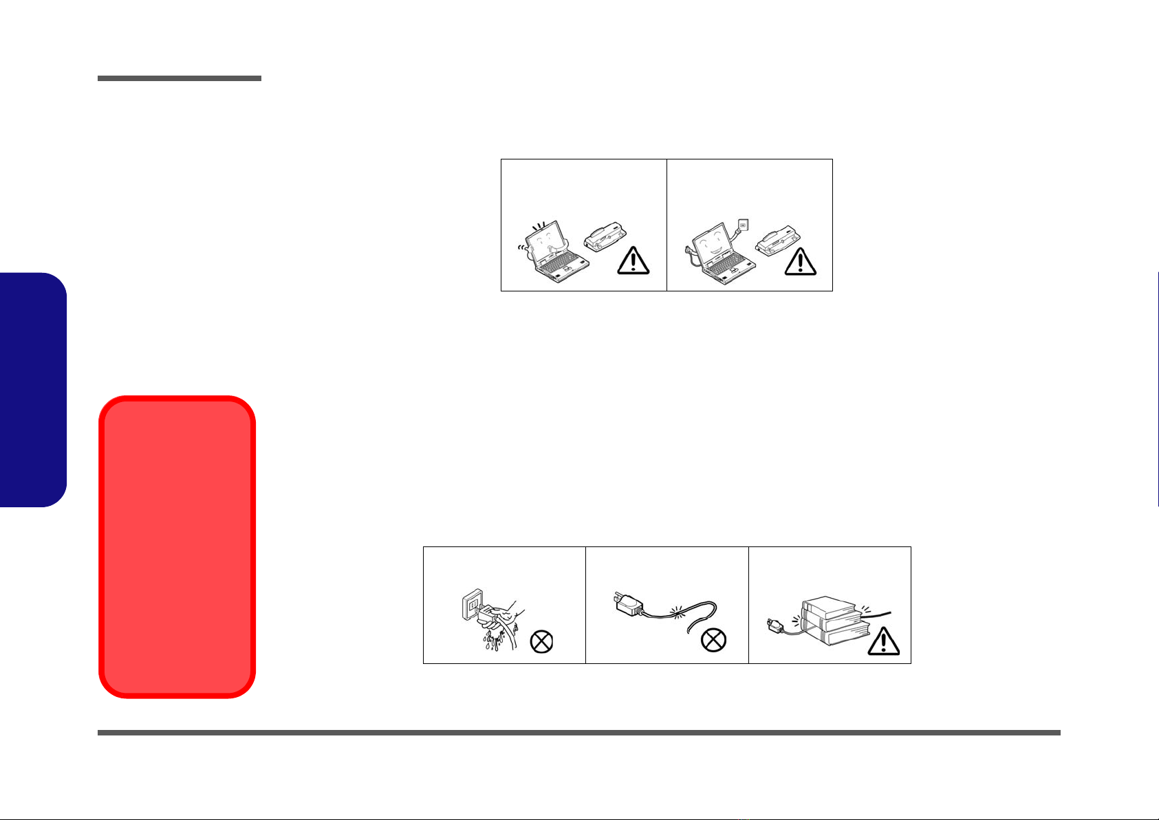
2. Keep it dry, and don’t overheat it. Keep the computer and power supply away from any kind of heating element. This
is an electrical appliance. If water or any other liquid gets into it, the computer could be badly damaged.
3. Follow the proper working procedures for the computer. Shut the computer down properly and don’t forget to save
your work. Remember to periodically save your data as data may be lost if the battery is depleted.
Do not expose the computer
to any shock or vibration. Do not place it on an unstable
surface. Do not place anything heavy
on the computer.
Do not expose it to excessive
heat or direct sunlight. Do not leave it in a place
where foreign matter or mois-
ture may affect the system.
Don’t use or store the com-
puter in a humid environment. Do not place the computer on
any surface which will block
the vents.
Do not turn off the power
until you properly shut down
all programs.
Do not turn off any peripheral
devices when the computer is
on.
Do not disassemble the com-
puter by yourself. Perform routine maintenance
on your computer.

Preface
VI
Preface
4. Avoid interference. Keep the computer away from high capacity transformers, electric motors, and other strong mag-
netic fields. These can hinder proper performance and damage your data.
5. Take care when using peripheral devices.
Power Safety
The computer has specific power requirements:
• Only use a power adapter approved for use with this computer.
• Your AC adapter may be designed for international travel but it still requires a steady, uninterrupted power supply. If you are
unsure of your local power specifications, consult your service representative or local power company.
• The power adapter may have either a 2-prong or a 3-prong grounded plug. The third prong is an important safety feature; do
not defeat its purpose. If you do not have access to a compatible outlet, have a qualified electrician install one.
• When you want to unplug the power cord, be sure to disconnect it by the plug head, not by its wire.
• Make sure the socket and any extension cord(s) you use can support the total current load of all the connected devices.
• Before cleaning the computer, make sure it is disconnected from any external power supplies.
Use only approved brands of
peripherals. Unplug the power cord before
attaching peripheral devices.
Do not plug in the power
cord if you are wet. Do not use the power cord if
it is broken. Do not place heavy objects
on the power cord.
Power Safety
Warning
Before you undertake
any upgrade proce-
dures, make sure that
you have turned off the
power, and discon-
nected all peripherals
and cables (including
telephone lines). It is
advisable to also re-
move your battery in
order to prevent acci-
dentally turning the
machine on.

Preface
VII
Preface
Battery Precautions
• Only use batteries designed for this computer. The wrong battery type may explode, leak or damage the computer.
• Do not continue to use a battery that has been dropped, or that appears damaged (e.g. bent or twisted) in any way. Even if the
computer continues to work with a damaged battery in place, it may cause circuit damage, which may possibly result in fire.
• Recharge the batteries using the notebook’s system. Incorrect recharging may make the battery explode.
• Do not try to repair a battery pack. Refer any battery pack repair or replacement to your service representative or qualified service
personnel.
• Keep children away from, and promptly dispose of a damaged battery. Always dispose of batteries carefully. Batteries may explode
or leak if exposed to fire, or improperly handled or discarded.
• Keep the battery away from metal appliances.
• Affix tape to the battery contacts before disposing of the battery.
• Do not touch the battery contacts with your hands or metal objects.
Battery Guidelines
The following can also apply to any backup batteries you may have.
• If you do not use the battery for an extended period, then remove the battery from the computer for storage.
• Before removing the battery for storage charge it to 60% - 70%.
• Check stored batteries at least every 3 months and charge them to 60% - 70%.
Battery Disposal
The product that you have purchased contains a rechargeable battery. The battery is recyclable. At the end of its useful life, under var-
ious state and local laws, it may be illegal to dispose of this battery into the municipal waste stream. Check with your local solid waste
officials for details in your area for recycling options or proper disposal.
Caution
Danger of explosion if battery is incorrectly replaced. Replace only with the same or equivalent type recommended by the manufacturer.
Discard used battery according to the manufacturer’s instructions.
Battery Level
Click the battery icon in the taskbar to see the current battery level and charge status. A battery that drops below a level of 10%
will not allow the computer to boot up. Make sure that any battery that drops below 10% is recharged within one week.

Preface
VIII
Preface
Related Documents
You may also need to consult the following manual for additional information:
User’s Manual on CD
This describes the notebook PC’s features and the procedures for operating the computer and its ROM-based setup pro-
gram. It also describes the installation and operation of the utility programs provided with the notebook PC.

Preface
IX
Preface
Contents
Introduction ..............................................1-1
Overview .........................................................................................1-1
System Specifications .....................................................................1-2
External Locator - Top View with LCD Panel Open ......................1-4
External Locator - Front & Right side Views .................................1-5
External Locator - Left Side & Rear View .....................................1-6
External Locator - Bottom View .....................................................1-7
Mainboard Overview - Top (Key Parts) .........................................1-8
Mainboard Overview - Bottom (Key Parts) ....................................1-9
Mainboard Overview - Top (Connectors) .....................................1-10
Mainboard Overview - Bottom (Connectors) ...............................1-11
Disassembly ...............................................2-1
Overview .........................................................................................2-1
Maintenance Tools ..........................................................................2-2
Connections .....................................................................................2-2
Maintenance Precautions .................................................................2-3
Disassembly Steps ...........................................................................2-4
Removing the Battery ......................................................................2-5
Removing the Hard Disk Drive .......................................................2-6
Removing the Keyboard ..................................................................2-8
Removing the System Memory (RAM) ..........................................2-9
Removing the Wireless LAN Module ...........................................2-10
Removing the 3G Module .............................................................2-11
Removing the Bluetooth Module ..................................................2-12
Removing the LCD .......................................................................2-13
Part Lists ..................................................A-1
Part List Illustration Location ........................................................A-2
Bottom ............................................................................................A-3
LCD ................................................................................................A-4
Schematic Diagrams.................................B-1
System Block Diagram ...................................................................B-2
Diamondville SC 1/2 ......................................................................B-3
Diamondville SC 2/2 ......................................................................B-4
945GSE 1/5, Host ...........................................................................B-5
945GSE 2/5 .....................................................................................B-6
945GSE 3/5, DDR ..........................................................................B-7
945GSE 4/5 .....................................................................................B-8
945GSE 5/5 .....................................................................................B-9
DDRII SO-DIMM - 0 ...................................................................B-10
CRT ...............................................................................................B-11
Panel, Inverter ...............................................................................B-12
Clock Generator ............................................................................B-13
ICH7-M 1/4, SATA ......................................................................B-14
ICH7-M 2/4, PCI, USB, SPI .........................................................B-15
ICH7-M 3/4 ..................................................................................B-16
ICH7-M 4/4 ..................................................................................B-17
USB Port, CCD, BT, LID SW ......................................................B-18
Mini Card, WLAN, 3G Card ........................................................B-19
LED, Fan, TP, Panel LED ............................................................B-20
Card Reader JMB261 ...................................................................B-21
LAN ..............................................................................................B-22
Audio Codec ALC269 ..................................................................B-23
KBC-ITE IT8502E .......................................................................B-24
AC-In, Charger .............................................................................B-25
3VS, 5VS, Power SW ...................................................................B-26
VDD3, VDD5, 3V, 5V .................................................................B-27
Power 1.8V/0.9V ..........................................................................B-28
Power 1.5VS/1.05VS, 2.5VS ........................................................B-29
VCORE .........................................................................................B-30

Introduction
Overview 1 - 1
1.Introduction
Chapter 1: Introduction
Overview
This manual covers the information you need to service or upgrade the M815L/M816L series notebook computer. Infor-
mation about operating the computer (e.g. getting started, and the Setup utility) is in the User’s Manual. Information
about drivers (e.g. VGA & audio) is also found in User’s Manual. That manual is shipped with the computer.
Operating systems (e.g. Windows XP, Windows Vista, etc.) have their own manuals as do application software (e.g. word
processing and database programs). If you have questions about those programs, you should consult those manuals.
The M815L/M816L series notebook is designed to be upgradeable. See “Disassembly” on page 2 - 1 for a detailed de-
scription of the upgrade procedures for each specific component. Please note the warning and safety information indi-
cated by the “” symbol.
The balance of this chapter reviews the computer’s technical specifications and features.

Introduction
1 - 2 System Specifications
1.Introduction
System Specifications
Processor
Intel® Atom® Processor N270
(1.6 GHz 512KB On-die L2 Cache & 533MHz FSB - BGA Package)
Intel® Atom® Processor N280
(1.66 GHz 512KB On-die L2 Cache & 533MHz FSB - BGA Package)
Core Logic
Intel® 82945GSE +82801GBM
Display
10.1” WSVGA (1024 * 600) TFT LCD
Memory
One 200 Pin SO-DIMM Socket Supporting DDRII (DDR2) 533 MHz
Memory
Memory Expandable up to 2GB
Video Adapter
Intel 945GSE Integrated Video
Supports DirectX 9.0
Shared Memory Architecture
(up to 128MB shared video memory dynamically allocated from system
memory where needed)
BIOS
One 8Mb SPI Flash ROM
Phoenix™ BIOS
Storage
One Changeable 2.5" 9.5 mm (h) SATA (Serial) Hard Disk Drive
Note: It is recommended that HDDs of a speed of 5400 RPM are used.
DO NOT use 7200rpm HDDs.
Security
Kensington Lock
Audio
High Definition Audio Compliant Interface
Compliant with Microsoft UAA (Universal Audio Architecture)
Direct Sound 3D™ Compatible
2 * Built-In Speakers
Built-In Microphone
Pointing Device
Built-in TouchPad (scrolling key functionality integrated)
Keyboard
“WinKey” keyboard (with embedded numeric keypad)
Interface
Two USB 2.0 Ports
One Headphone-Out Jack
One Microphone-In Jack
One External Monitor Port
One RJ-45 LAN Jack
One DC-in Jack
Communication
10Mb/100Mb Base-T Ethernet LAN
802.11b/g Wireless LAN Half Mini-Card Module (Option)
802.11b/g/n Wireless LAN Half Mini-Card Module (Option)
1.3M Pixel USB PC Camera Module (Factory Option)
*Bluetooth 2.1 + EDR (Enhanced Data Rate) Module (Factory Option)
*UMTS/HSPA-based 3.75G/HSPA Module with Mini Card Interface
(
Factory Option
)

Introduction
System Specifications 1 - 3
1.Introduction
Operating System
Windows XP with Service Pack 3, Windows 7
Card Reader
Embedded 7-in-1 Card Reader (MS/ MS Pro/ SD/ Mini SD/ MMC/ RS
MMC/ MS Duo)
Note: MS Duo/ Mini SD/ RS MMC Cards require a PC adapter
Slot
Two Mini-Card Slots (USB & PCIE)
Slot 1:
for Wireless LAN Module (Half Mini-Card)
Slot 2: for 3.75G/HSPA Module
Power Management
Wake On LAN
Wake On USB
Power
Full Range AC/DC Adapter
AC Input: 100 - 240V, 50 - 60Hz
DC Output: 19V, 1.57A/1.58A (30 Watts)
Battery
Polymer Battery Pack, 3550mAh
Environmental Spec
Temperature
Operating: 5°C - 35°C
Non-Operating: -20°C - 60°C
Relative Humidity
Operating: 20% - 80%
Non-Operating: 10% - 90%
Dimensions & Weight
271mm (w) * 188.6mm (d) * 19.5 - 28mm (h)
Around 1.2 kg With Battery
Optional
802.11b/g Wireless LAN Module
802.11b/g/n Wireless LAN Module
External USB Super Multi Optical Device Drive
1.3M Pixel USB PC Camera Module (Factory Option)
*Bluetooth 2.1 + EDR Module (Factory Option)
*UMTS/HSPA-based 3.75G/HSPA Module (
Factory Option
)

Introduction
1 - 4 External Locator - Top View with LCD Panel Open
1.Introduction
External Locator - Top View with LCD Panel Open
Figure 1
Top View
1. Optional Built-In
PC Camera
2. LCD
3. Speakers
4. Keyboard
5. Built-In
Microphone
6. Touchpad &
Buttons
2
5
1
4
6
3

Introduction
External Locator - Front & Right side Views 1 - 5
1.Introduction
External Locator - Front & Right side Views
Figure 2
Front Views
1. LED Power &
Communication
Indicators
2. 7-in-1 Card
Reader
3. Microphone-In
Jack
4. Headphone-Out
Jack
Figure 3
Right Side Views
5. Hard Disk Drive
Bay
6. Vent/Fan Intake/
Outlet
7. Security Lock
Slot
1432
57
6

Introduction
1 - 6 External Locator - Left Side & Rear View
1.Introduction
External Locator - Left Side & Rear View
Figure 4
Left Side View
1. DC-In Jack
2. RJ-45 LAN Jack
3. 2 * USB 2.0 Ports
4. External Monitor
Port
1234
3
Figure 5
Rear View
5. Battery
5

Introduction
External Locator - Bottom View 1 - 7
1.Introduction
External Locator - Bottom View
Figure 6
Bottom View
1. Battery
2. Vent/Fan Intake/
Outlet
3. Hard Disk Bay
Overheating
To prevent your com-
puter from overheating
make sure nothing
blocks the vent/fan in-
takes while the com-
puter is in use.
3
1
2
2

Introduction
1 - 8 Mainboard Overview - Top (Key Parts)
1.Introduction
Mainboard Overview - Top (Key Parts)
Figure 7
Mainboard Top
Key Parts
1. Card Reader
Socket
2. Audio Codec
3. Intel Atom CPU
4. North Bridge
5. Memory Slots
DDR2 SO-DIMM
6. Mini-Card
Connector
(WLAN Module)
1
3
4
2
6
5
This manual suits for next models
1
Table of contents
Other Clevo Laptop manuals