Clifford IntelliGuard 8000 User manual

Standard Features of the IntelliGuard 8000
System Components
The IntelliGuard 8000 kit contains the following components:
One Prewired 24-pin Connector Harness One PlainView 2 Coded Valet Switch
One Prewired 14-pin Connector Harness One Medallion Siren
One IntelliGuard 8000 Control UnitOne Hardware Kit
One Digital Dual-Zone Proximity Sensor 4One User’s Manual
Two Remote TransmittersTwo Window Decals
One Extended Range ReceiverOne LED Status Indicator
IntelliGuard 8000/2991
qLifetime Warranty
qHis & Hers Remote Controls
qACG™ 2 (Anti-CodeGrabbing™)
qExtended Range Receiver
qAudible Low-Battery Warning
qBuilt-In Two-Point Immobilizer™
qOptional Wireless Immobilizer™
qDigital Dual-Zone Proximity Sensor 4
qOptional Remotely Adjustable OmniSensor
qPatented UltraSecure Coded Valet Mode™
qEight-Event TotalRecall™
qEnhanced User-Selectable AutoArming
qUser-Selectable Remote Valet Mode Entry/Exit
qBuilt-In BlackJax Anti-Carjacking System
qOptional DataPort™ Interface and CliffNet Wizard
Pro™ Software
qFACT — False Alarm Control and Test
qPrewired LED, Sensor, Extended Range Receiver and
PlainView 2 Switch Connectors
qHigh Output Medallion Siren
qDual-Mode “Chirp” Silencing
qRemote Siren Silencing
qRemote Door Locking/Unlocking with Built-in Relays
qUser-Selectable AutoLock
qUser-Selectable AutoUnLock
qIntegrated Electronic Timer
qTurbo Timer Output
qCliffNet DataPort Accessory Interface
qRemote Keyless Entry and Accessory Activation Even in
Valet Mode
qRemote Panic with Smart Locking/Unlocking
qSmart Remote Trunk Release
qBuilt-In Dual Parking Light Flasher with Onboard Relay
qRemote-Controlled Courtesy Lighting
qPatented Smart AutoTesting™
qPatented Malfunction AutoBypass™ with
AutoReMonitoring
qPatented Smart Prior Intrusion Attempt Alert
q
Patented Remote Control Code Learning and MultiRemote
Recognition
qClear All Remotes
qMultiple-Car Control
qHigh-Luminescence LED Status Indicator with Automatic
Battery-Saving Mode
qMultiple Sensor/Trigger Inputs
qPatented SmartPowerUp™ 2
qFull-Time SecureAccess™ Programming
qAdvanced CMOS Microcomputer
qPre-Loomed Wiring
qThree Auxilliary Outputs with Selectable Output Types
qAutoActivation of Auxilliary Output C for Window
All-Close
qInstaller-Selectable Door Ajar/Delayed Courtesy Lights

Wiring Description for the 24-Pin Connector
PinColorConnects to
2Red/BlackOptional Digital OmniSensor input (5V+)
3White/BluePrewired Digital Proximity Sensor input connector
4VioletLED Output (+) 12V
5Black/GrayTach input
6RedProximity Sensor and Tilt Sensor power supply (+) 12V
8Gray/YellowTrunk trigger switch input (-)
9Black Sensors, LED and valet switch ground supply (-)
10 Black Ground
11WhiteValet Switch input (-) multi-plex
13 Gray/VioletAuxilliary Output A output
14 Gray/BlueAuxilliary Output B output
15 Gray/RedAuxilliary Output C output
16 White/BlueOptional remotely adjustable OmniSensor input
17 YellowOptional airhorns or siren output (-)
18 RedBattery input (+12v)
19 Black twinleadMedallion Siren output
20 GreenTilt Sensor armed output
21Black twinleadMedallion Siren output
23 White/BlackHood trigger switch input (-)
24 OrangeTilt Sensor input (-)
2IntelliGuard 8000/299

IntelliGuard 8000/2993

Wiring Description for the 14-Pin Connector
PinColorConnects to
1BrownParking light output (+)
2Blue/WhiteBrake light input/output (+)
3BrownParking lights output (+)
6White/OrangeDoor lock common
7White/GreenDoor lock common
8Red/WhiteParking & brake supply
9Brown/RedInterior light supply
10 GrayDoor trigger
11 Red/OrangeDoor unlock normally open
12 Red/Green Door lock normally open
13 Gray/GreenDoor lock normally closed
14 Gray/OrangeDoor unlock normally closed
Wiring Description for the Pigtail Connector
PinColor Connects to
1Green/BlueIgnition output (+12v)
2White/BlueStarter output (+12v)
3White/BrownIgntion input (+12v)
4White/Green Starter input (+12v)
4IntelliGuard 8000/299

IntelliGuard 8000/299 5

Passenger Compartment Connections
Control Unit and Extended Range Receiver
The IntelliGuard 8000 control unit must be installed inside the vehicle. Under no circumsta nces should the unit
be installed under the hood or other similarly hostile environment.
1.Select an area behind the dash to mount the control unit using the supplied wire tires, but do not permanently affix it until all
wiring and testing is complete.
2. Plug the extended range receiver in to the control unit. Mount the extended range receiver away fr om the control unit and run
the antenna either up the window pillar and affix it to the windshield, or under the dash, away from metal. The position and
location of the receiver will effect remote control range. Do not fold the excess cable or antenna wire. Do not make hard, sharp
bends.
Door Trigger/Interior Light Supply
Please refer to theDoor Trigger/Interior Light Supply section in this binder for information on polarity testing and connections.
Central Door Locking System
Please refer to the Door Lockssection in this binder for information on circuit types and connections.
LED Status Indicator
Select a prominent location on the dash or console visible through all windows. Discuss placement with the owner.
1.Verify there is adequate space to accommodate the LED, then drill a 5/16” (8mm) hole and route the wires through it.
2. Mate the LED connectors to the VIOLET and BLACK wire connectors as shown in the diagram on page 3.
3.Press the LED into place.
PlainView 2 Coded Valet/Programming Switch
1.Discuss placement of the switch with the vehicle owner and avoid placing the switch where it can bepressed accidentally.
2.Verify there is adequate space behind the selected location to accommodate the switch.
3.Drill a 5/16” (8mm) mounting hole, then insert the wires through the hole.
4.Mate the switch’s locking connectors to the WHITE and BLACK locking connector.
5.Remove the adhesive backing and press the switch into place.
Remotely Adjustable Dual-Zone Proximity Sensor
This efficient new-generation proprietary radar sensor is immune to the wind and temperature variations that cause ultrasonic
sensors to false alarm. The sensor must be mounted onto a metal surface and face outward into the passenger compartment. It should
be positioned as close as possible to the center of the passenger compartment. Suggested mounting l ocations include within the
centre console, behind the dash, under the carpeting of the central hump or even in the headlining.When selecting a location, keep
in mind that metal as well as metallic paint, metallic-colored plastic and metal-laced window tint material will interfere with the
radar field. Be certain not to mount the sensor under a location where the vehicle owner may store coins, CDs or cassettes
(iron-oxide tape). The radar waves of the sensor willpass through nonmetallic materials such as plastic, fabric and carpet.
1.Temporarily affix the sensor where it will be mounted, but do not yet permanently mount it until after adjusting and testing
sensitivity (the sensor may need to be relocated, so do not permanently secure it until it has beenthoroughly tested).
2.Join the Proximity Sensor to the connector with the BLACK, WHITE/BLUE and RED wires.
Trunk Trigger
Vehicles with a ground-switching trunk light will interface directly with the IntelliGuard 8000 (onpositive switching vehicles, use a relay to
invert polarity). The switch may be located in or near the trunk latch or at the trunk light. If aswitch cannot be located, you must add a pin
switch in a location away from water channels.
NOTE: If the vehicle has a dashboard trunk ajar indicator, install a 1-amp diode between the light and switch
with the diode band pointing toward the switch.
1. Connect the GRAY/YELLOW wire to the trunk switch (between the diode and switch if you added a diode ).
6IntelliGuard 8000/299

Passenger Compartment Connections
Brake Switch
The brake switch connection is required for the operation of the IntelliGuard 8000’s anti-carjacking electronics.
1. Turn the ignition to the “ON” position and press the brake pedal to verify that the brake lights ar e operational.
2. Find the one wire that carries +12V when the brake pedal is pressed, then connect the BLUE/WHITE wire to this wire.
Parking Lights
See the Door Trigger/Parking light section in this binder.
Starter and Ignition Immobilization Circuits
1.Locate the ignition switch wireloom under the dash and use a voltmeter to locate the one wire that carries +12V throughout
BOTH the cranking AND engine running cycles, and 0 volts when the ignition is off.
2. Start the engine, then cut the ignition wire. The engine should stop running.
3.As shown on page 5, connect the WHITE/BROWN wire to the key sideof the cut ignition line.
4.Connect the GREEN/BLUE wire to the engine side of the cut ignition line.
5.Use a voltmeter to locate the one wire that carries +12V during the cranking cycle ONLY. Cut this wire, then try to start the
engine. It should not crank.
6. Connect the WHITE/GREEN wire to the key sideof the cut starter line.
7.Connect the WHITE/BLUE wire to the engine side of the cut starter line.
NOTE:Thestartercircuitmaycarryaveryhigh current.Be certainthat thestarter wireconnections are solid.
Auxilliary Output A with Selectable Output Type
The output (GRAY/VIOLET wire) can be programmed as either pulsed, latched or timed and can be progr ammed to operate only
when the system is disarmed (e.g., for use as a remote trunk release). The output is activated by transmitting channel 2 from the 16-
channel master remote control or by pressing the button on the companion remote. The factory setting is pulsed output (0.5
second ground). The latched output stays at ground until channel 2 is activated a second time, and the timed output stays at ground
for any selected duration between one second and four minutes. Current is limited to 0.15 amp. See Installer-Programmable Features
on
page 16 for information on programming the output type and/or disabling operation while the system is disarmed.
Auxilliary Output B with Selectable Output Type
The output (GRAY/BLUE wire) can be programmed as either pulsed, latched or timed and is activated by transmitting channel 7
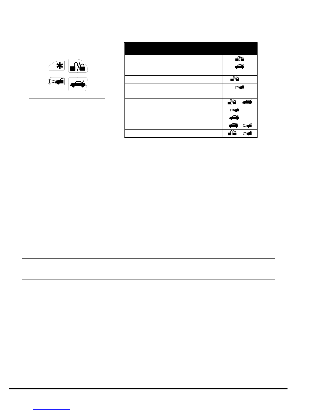
from the 16-channel master remote control or by pressing the and ✱ buttons on the companion remote. The factory setting is
pulsed output (0.5 second ground). The latched output stays at ground until channel 7 is activateda second time, and the timed
output stays at ground for any selected duration between one second and four minutes. Current is limited to 0.15 amp. See
Installer-Programmable Featureson page 16 for information on programming the output type.
Auxilliary Output C with Selectable Output Type and AutoActivation
The output (GRAY/RED wire) can be programmed as either pulsed, latched, or timed and in addition, can also be programmed to
automatically activate every time the system is armed using the remote control. The output is activated by transmitting channel 8 from
the 16-channel master remote or by pressing and on the companion remote. Current is limited to 0.15 amp. AutoActivation is
perfect when programmed as a timed-output to close the power windows and sunroof on vehicles that h ave an all-close feature. See
Installer-Programmable Featureson page 16 for more information on programming output type and/or enabling the AutoActivation
feature.
Engine Bay Connections
High Output Medallion Siren
Mount the siren in the engine compartment away from hot or moving parts and where it cannot be reac hed from under the vehicle,
preferable opposite the exhaust system. Point the siren down to avoid water collection (see the il lustration).
1.You must firmly secure the siren to the engine bay firewall or an fender well using all three sheetmetal screws supplied.
2.Using the supplied connector, fasten the GRAY twinlead wire coming from the siren to the BLACKtwinlead from the 24-pin
connector on the control unit.
IntelliGuard 8000/2997

RPM Monitoring
This is required for both RPM-activated automatic door locking and for BlackJax anti-carjacking features. See the RPM Monitoring
section in this binder for information.
Hood Trigger
Vehicles with a ground-switching hood pin switch interface directly with IntelliGuard 8000 (on posi tive switching vehicles, use a relay to
invert polarity).If a switch cannot be located, you must add a pin switch in a location away from water channels.
1. Connect the WHITE/BLACK wire to the hood pin wire.
Final Wiring Connections
1.Connect the 18 AWG RED wire to the 5-amp fuseholder as shown on page 3.
2.Connect the 18 AWG RED/WHITE wire to the 20-amp fuseholder as shown on page 5.
3.Attach the two fuseholders to the battery positive cable clamp.
4.Attach the 18 AWG BLACK wireto the battery negative cable clamp.
NOTE:Power andtest accessoriesafter thebasic systemhasbeen tested.Individually fuseallaccessory power
connections. Individually fuse all +12V fuse panel connections.
SmartPowerUp™ 2
SmartPowerUp 2 ensures that the system powers up in the same state (disarmed, armed or valet mode) it was in when power was removed.
When you first power up the IntelliGuard 8000, it will silently enter the disarmed state.
Delayed Courtesy Lights
Some vehicles have a courtesy light delay or dimming circuit, which interferes with an alarm being able to detect the doortrigger upon
remote arming. If the delay or dimming lasts more than 5 seconds, no special connections or testingare needed,simply turn on the Delayed
Courtesy Lightsfeature as noted in the Installer-Programmable Featuressection on page 16. Please note that since this feature sets the
system to arm the instant the courtesy lights turn off, the Door Ajar Warning feature will not be a vailable.
Mandatory RPM Programming
NOTE:ThisMANDATORYprogramming stepmust becompletedfortheIntelliGuard8000tooperateproperly.
1.Drivethe vehicle to a nearby open area and allow the engine to warm-up until the RPMs drop to the norma l idle speed.
2. With the engine still running, place the transmission in Park (or Neutralif the vehicle has a manual transmission).
3. Enter the code of “2” valet code using the instructions provided in the Programmable Features on page 14. The LED will briefly
illuminate. Press and hold the ✱button for 10 seconds (you will hear one confirmation chirp after three seconds—do not stop
holding the button—continue holding the button until you hear a three-chirp confirmation). Releasethe button.
4.Press the unmarked button once. After a three-second pause, the system will sound one chirp to confirm column one sel ection
(see the Installer-Programmable Featuressection on page 16).
5.Press the ✱button five times (you will hear a chirp each time you press the button) to select row five. Aftera two-second pause,
you will hear two chirps to confirm idle RPM has been set (if you hear just one chirp, check the connection of the BLACK/GRAY
wire, then repeats steps 1 - 5).
6. Turn the ignition OFF.
Remote Control Operation
The IntelliGuard 8000 comes with two ergonomically designed remote controls: a 16-channel master remote and a 10-channel
secondary “companion” remote. Up to two more ACG 2 remote controls can be added to the IntelliGuard 8000 system. Due to the
ACG 2 feature on the IntelliGuard Series systems, older Clifford ACG and non-ACG remotes are not compatible with the
IntelliGuard 8000.
8IntelliGuard 8000/299

16-Channel Master Remote Control Operation
To transmit either channel 1, 2, 3 or 4:Press button 1, 2, 3 or 4. The LED indicator on the
remote control will flash once every second: this indicateslevel 1.
To transmit either channel 5, 6, 7 or 8:Press the LevelShift button once. This shifts buttons
1–4 to level 2 (channels 5–8). Then press the desired button within the next 7 seconds. For
instance, to transmit channel 5, press the LevelShift button once, then press button 1. The
LED indicator on the remote control flashes twice, pauses, flashes twice, etc.: this indicates
level 2.
To transmit channel 9, 10, 11 or 12: Press the LevelShift button twice. This shifts the buttons to level 3 (channels 9–12). Then press
the corresponding button within the next 7 seconds. For instance, to transmit channel 10, press the LevelShiftbutton twice, then press
button 2. The LED on the remote control flashes three times, pauses, flashes three times, etc.: this indicates level 3.
To transmit channel 13, 14, 15 or 16:Press the LevelShift button three times. This shifts the buttons to level 4 (channels 13–16).
Then press the corresponding button within the next 7 seconds. For instance, to transmit channel 14 press the LevelShiftbutton three
times, then press button 2. The LED on the remote control flashes four times, pauses, flashes four times, etc.: this indicates level 4.
NOTE: One second after you stop transmitting levels 2, 3 or 4 (channels 5–16), the remote con trol
automatically returns to level 1 (channels 1–4).
Remote Control Channel Assignments
Channel # FunctionChannel # Function
1Arm/Disarm9Remote Valet
2*Activate Auxilliary Output A
(usually remote trunk release)*10 Proximity Sensor Override
3Silent Arm/Disarm11*Manual Transmission enable/AutoStart
(IS4 required)
4IntelliStart 4 Activation12*Unassigned*
5*Parking Lot Highlight Activation*13* Unassigned*
6*SmartWindows 4 Accessory*14*Unassigned*
7*Activate Auxilliary Output B*15 Adjust Sensitivity of Optional OmniSensor
8*Activate Auxilliary Output C*16 Adjust Sensitivity of Proximity Sensor
* These channels can be assigned to control other Clifford ACG 2 systems and accessories on multiple vehicles.
IntelliGuard 8000/2999

Companion Remote Control Operation
Sensor Adjustment
Digital Dual-Zone Proximity Sensor 4
The IntelliGuard 8000 is equipped with our unique Digital Dual-Zone Proximity Sensor that uses digital signal processing to detect
movement inside the passenger compartment and very near the vehicle. If a thief were to break a window and either enter or lean
into the passenger compartment, the primary zone of this sensor would trigger the full alarm. Howev er, if a thief brought his hands
and face to the window a warning tone would sound.
Be aware that the Proximity Sensor uses radar waves to detect movement. These waves pass through nonmetallic materials like
plastic, carpet, glass and wood. However, metal and metallic-colored paint, metallic-colored plasti c and even some metallic window
tinting materials will interfere with or completely block the radar waves. As such, it is not unusual that the Proximity Sensor zones
require some adjustment after installation. In some instances, you may need to try a different location for the sensor.
Since any metal objects above or near the Proximity Sensor will have a significant impact onoperation, warn
your customer never to place coins, CDs, cassettes (due to the iron oxide tape) or other metallic objects above
or near where the sensor is mounted.
1.Turn off any fluorescent lights that may interfere with the sensitivity testing of the IntelliGuard8000’s radar sensor.
2.Disarmthe system with the remote control.
3.Transmit channel 16on the master remote (LevelShift three times, then button 4). You will hear one chirp and the LED will turn on.
4. Test the Proximity Sensor’s primaryzone by rapidly leaning through an open window into the passenger compartment. You will
hear a siren chirp when the primary zone is triggered. This should not occur near the window, but instead when you would be in a
position to touch the car stereo.
To change the sensitivity of the primary zone, press and release button 2 to increasesensitivity or button 4 to decreasesensitivity.
To rapidly increase or decrease several steps, press and hold the button. For each sensitivity incr ease, you will hear a higher and
higher pitched confirmation chirp. For each sensitivity decrease, you will hear a lower and lower pitched confirmation chirp. Two
LoudChirps indicate minimum and maximum settings of the 32-step range of settings. You may now pres s button 3to adjust the
warning zone, or press button 1to fully exit the Proximity Sensor adjustment mode (you will hear 3 chirps).
10IntelliGuard 8000/299
*These channels/buttons can be assigned to control other Clifford
systems that use ACG 2 technology and accessories on other vehicles.
FunctionPress button
number(s)
Arm/Disarm
Activate Auxilliary Output A*
(usually remote trunk release)*
Silent Arm/Disarm+ ✱
Parking Lot Highlight activation
IntelliStart 4 Accessory*✱
SmartWindows 4 Accessory*+
Remote Valet Mode Enter/Exit*+ ✱
Activate Auxilliary Output B+ ✱
Activate Auxilliary OutputC+
Remote Proximity Sensor Override+

Sensor Adjustment (Continued)
To change the sensitivity of the warningzone, press button 3
(you’ll hear 1 chirp). Then use the same procedure as above, but this
time, rapidly bring your hands and face to the window as a thief would to see what’s inside. The sensitivity of the warning zone
should be set so that it is triggered when your face and hands are within a few inches of the window, no further. When done, press
button 1 to reselect the primary zone (you will hear 2 chirps), then button 1 again to fully exit ProximitySensor adjustment mode
(you will hear 3 chirps).
5.Repeat the preceding steps as required. An improperly adjusted sensor will cause the IntelliGuard 8000 to false alarm or not
respond properly to a genuine threat. Keep in mind that you may need to reposition the sensor, pos
sibly after the customer has had
the system for several days.
Remote-Controlled Override of Each Proximity Sensor Zone
Transmitting channel 10 whenever the system is armed will override the warning zone of the Proximit y Sensor. This prevents the
system from sounding warnings if the vehicle must be parked in an area with heavy pedestrian traffic. A second transmission of
channel 10 anytime afterward whilst the system is still armed will override bothzones of the Proximity Sensor. This comes in handy
when a pet or a passenger must be left in the vehicle. The channel 10 warning zone override is visually confirmed with 4 flashes of
the parking lights. A second channel 10 transmission to override both zones is confirmed with four
more flashes. The sensor zones are
automatically restored the next time you arm.
FACT—False Alarm Control and Test
The system microprocessor automatically checks for another activated sensor or trigger before sounding the siren a second time, thus
preventing any further false alarms. If you wish to test FACT, simply:
1.Arm the IntelliGuard 8000 with the remote control.
2.Wait 10 seconds after the interior light turns off, then trigger the Proximity Sensor to activate the siren.
3.Do not disarm the system, let the siren complete its cycle.
4.Attempt to trigger the sensor again. The alarm should be silent.
5.Unlock and open a door. The alarm should sound immediately. You may now disarm.
Eight-Event TotalRecall
The system’s nonvolatile memory records the identity of the last eight activated or malfunctioning triggers and sensors:
NOTE: The CliffNet Wizard Pro displays the Eight-Event TotalRecall data in a graphical forma t.
1.With the ignition OFF, press and hold the unmarked side of the PlainView 2 Switch.
2. Use the remote control to arm, and then again to disarm, and then release the button.
3.The LED will flash 1–10 times, pause, then flash 1–10 times, etc. Write down the number of flashes in each cycle.
4.Refer to the following chart. The first number you wrote down was the most recently activated trigger or sensor. The next number
is the second most recent, and so on up to as many as the last eight activations.
Number of LED flashes between pausesTrigger/sensor indication
1 flash Digital Dual-Zone Proximity Sensor
2 flashesOptional Remotely Adjustable OmniSensor
3 flashesOptional Digital Tilt/Motion Sensor
4 flashesDoor Trigger
5 flashes 0Trunk Trigger
6 flasheswhile
7 flashesAn attempt was made to turn on the
ignition or start the engine while the system was armed
8 flashesMore than three consecutive incorrect
valet codes were entered while the system was in BlackJax mode
9 flashes BlackJax Activation
10 flashesSystem Power Interruption
5.If a sensor is often activated, decrease that sensor’s sensitivity (or reposition the sensor, if necessary). If a certain trigger is often
activated, check pin switch operation, verify that the pin switch is not exposed to moisture and check the trigger wire for possible
shorting.
IntelliGuard 8000/299 11

Programmable Features
IntelliGuard 8000 comes from the factory with its features preprogrammed as noted in boldtext in the tables on pages 15 and 16.
Some features can be programmed by the installer or the user, others can only be programmed only bythe installer. There are two
tables provided which define the user-programmable and installer-programmable features.
Using the CliffNet Wizard Pro
The CliffNet Wizard Provides intuitive access to all installer and user-programmable features through a user-friendly, graphical user
interface. Because CliffNet Wizard Pro is Windows™-compatible, most operations can be accomplishedby simply pointing and
clicking a mouse. CliffNet Wizard Pro totally eliminates complicated programming charts and lengthy programming sequences.
Please refer to the CliffNet Wizard Pro User’s Guidefor more programming information if you are using the CliffNet Wizard Pro.
Otherwise, for manual programming refer to the tables provided in the following sections.
Programming the User-Selectable Features
1.Write down the column (across) number and row (down) number of the feature(s) you wish to program.
2.Turn the ignition to the “ON” position or start the engine.
3.Enter the factory preset valet/programming code of “2” by pressing the PlainView 2 Switch’s ✱button twice, then press the
unmarked button.
4.After entering the code, press and hold the ✱for about 3 seconds until you hear one siren chirp and the LED turns on to
acknowledge program mode entry. The IntelliGuard 8000 is now in the “Feature Select” position for User-Programmable Features.
5.Select the feature column: Press the unmarked button the same number of times as the column number.Pause. You will then hear
the same number of chirps as the column number you have selected, audibly confirming your selection.
6.Within five seconds, select the feature row: Press ✱button the same number of times as the feature’s row number. You’ll hear a
chirp each time you press the unmarked side to help you count.
7.If there is aNOTE for the selected feature, perform the actions noted.
8. Pause. You will hear either one or two chirps: two chirps = ON, one chirp = OFF.
9.You can select another feature, or you can exit program mode:
a.To select another feature in that same column, repeat step 6 within the next five seconds (after five seconds, three chirps
indicate that the IntelliGuard 8000 is now back in the “Feature Select”position).
b.To select a different feature column, repeat step 5.
c.To exit program mode, turn the ignition off (you’ll hear three chirps and the LED will turn off to indicate exit of program
mode), or wait 60 seconds and the IntelliGuard 8000 will automatically exit program mode.
It may sound a little complicated, but it really isn’t. Briefly, here is all you do: choose the feature you want to change, enter program
mode, select that feature’s column and row, wait for the on/off chirp confirmation, then turn off t he ignition. That’s it!
12IntelliGuard 8000/299

User-Programmable Features
User-Programmable Features (1 Chirp = OFF, 2 Chirps = ON)
Feature
SelectUnmarked 1 Unmarked 2 Unmarked 3 Unmarked 4
✱ 1AutoProgram New Master
Remote
NOTE 1
Chirps
(Off/LoudChirps/QuietChirps)
(1 chirp/2 chirps/3 chirps)
AutoArming
(Off/On)
Arm/Disarm with
Secondary Remote
NOTE 5
✱ 2Personalized Siren Sounds
NOTE 2 NOT USEDAutoArm&Lock
(Off/On)
Trunk Release with
Secondary Remote
NOTE 6
✱ 3Play Siren Sounds
(Always/Trigger Only)
(1chirp/2 chirps)
Remote Valet Feature
(Off/On)Entry Delay
(Off /On)
Silent Arm/Disarm with
Secondary Remote
NOTE 6
✱ 4Siren Duration
(30 /60/90 Seconds)
(1 chirp/2 chirps/3 chirps)
AutoStart
(Neither/Battery/Temperature/Both)
(1 chirp/2 chirps/3 chirps/4 chirps)
Requires optional Intellistart 4
FACT
(Off/On)
Parking Lot Highlight
Activation with Secondary
Remote
NOTE 6
✱ 5AutoLock
(Off/Instant/RPM-Dependent)
(1 chirp/2 chirps/3 chirps)
BlackJax
(Off/On) NOT USEDRemote Start** with
Secondary Remote
NOTE 6
✱ 6AutoUnlock
(Off/On)Clear All Remotes
NOTE 4NOT USEDWindow Rolldown/Venting
with Secondary Remote
NOTE 6
✱ 7
Reset All to Factory Settings
(except remote controls and
valet code)
NOTE 3
Valet Code
SHOULD ONLY BE
PROGRAMMED BY THE VEHICLE
OWNER
NOT USEDRemote Valet Mode
with Secondary Remote
NOTE 6
nNOTE 1:Press button 1 on the 16-channel master remote, you will hear one chirp. Press button 1 again,you will hear two
chirps.
nNOTE 2:When this feature is selected, siren sound 1 will play for five seconds. Press marked to turn thesiren sound off,
press unmarked to activate the sound. Next, siren sound 2 will play for five seconds. Press marked to turn the siren sound
off, unmarked to activate it. The system will cycle through all six siren sounds.
nn NOTE 3:You will hear two chirps when all features are reset.
nNOTE 4:When you hear two chirps, all remote controls will have been erased from the system memory. You must now add
the new and/or existing remote controls to the system (i.e., AutoProgram each remote that will be used with the
IntelliGuard 8000).
nNOTE 5:Programs a 4-channel secondary, 16-channel master, or any other remote control from another Intell iGuard
system to arm or disarm the vehicle. For instance, to set button 13 of the other car’s master remot e control to arm/disarm
the system, select column 4, row 1, then transmit channel 13 from the remote you are programming. T he system will
respond with one chirp. Immediately transmit channel 13 again. The system will respond with two chirps. Button 13 of the
other vehicle’s remote will now arm/disarm the system.
nNOTE 6:This feature can be programmed onto the remote control of another IntelliGuard system, after that remote has
been programmed to arm/disarm this system. Select the row and column number, then transmit the unused button on the
other remote that you want to use to perform that function. The IntelliGuard 8000 will respond withthe same number of
chirps as the row number. Please note that you must first set a button on the remote that will arm/ disarm the system
(column 4, row 1) before these others will be accepted.
IntelliGuard 8000/29913

Installer-Programmable Features
To access the installer-programmable features, use the procedure defined in the User-Programmable section, but in step 4, hold and
press the ✱side of the PlainView 2 Switch for 10 seconds. You will hear three confirmation chirps indicating that the system is in
installer-program mode.
Table of Installer-Programmable Features (1 chirp = OFF, 2 chirps = ON)
Feature
SelectUnmarked 1 Unmarked 2 Unmarked 3
✱1 Single/Double Lock Pulse
(1 chirp/2 chirps)
Auxilliary Output Timer
Duration
(10 seconds)
See NOTE 1
Door Ajar Warning /Delayed
Courtesy Lights
(1 chirp/2 chirps)
✱2Single/Double Unlock Pulse
(1 chirp/2 chirps)
Auxilliary Output A Type
(Pulsed/Timed/Latched)
(1 chirp /2 chirps/3 chirps)
Auxilliary Output A Interlock
(On/Off)
✱3Lock/Unlock Pulse
3 second/1 second
(1 chirp/2 chirps)
Auxilliary Output B Type
(Pulsed/Timed/Latched)
(1 chirp /2 chirps/3 chirps)
Auxilliary Output B Interlock
(On/Off)
✱4 AutoActivate Auxilliary Output C
upon Remote Arming
(On/Off)
Auxilliary Output C Type
(Pulsed/Timed/Latched)
(1 chirp /2 chirps/3 chirps)
Auxilliary Output C Interlock
(On/Off)
✱5 Program RPM
See
Mandatory RPM Programming
Diesel Engine/GasEngine
(1 chirp/2 chirps)
(For IntelliStart 4 only)*
Program optional
SmartWindows 4
See NOTE 2
✱6 Auxiliary Siren Output
(Constant/Pulsed)
(1 chirp/2 chirps)Learn PageMate 4 IDNOT USED
* Must program RPM’s AFTER changing this feature
nNOTE 1: Once this feature is selected, one chirp is provided to indicate that the timer has started. You can set this anywhere
from one second to 4 minutes. When the desired duration has been reached, press the unmarkedside of the PlainView 2
switch. The system responds with two chirps to confirm the new system timer duration.
System Checklist & Troubleshooting
The following checklist and troubleshooting tips will assure that you have installed the IntelliGuard 8000 correctly. If the system does
not react as noted, follow the troubleshooting tip(s) denoted with a black box below that it em, then repeat the step. Each successive
step requires that the previous step has been completed as indicated.
The Clifford Wizard simplifies the troubleshooting process by providing system diagnostic information in a graphical format. All
system settings are provided at-a-glance, and adjustments to the system settings can be made with aclick of a mouse. This reduces
the amount of time required for performing the following tests.
Step 1.
Re-enable the courtesy lights.
In step 1 of the ImportantInformation section in this binder, the interior courtesy lights were disabled. You must now re-enable
the courtesy lights by replacing the fuse you removed or reset the courtesy light switch back to its normal “DOOR” position before
proceeding.
14IntelliGuard 8000/299

System Checklist & Troubleshooting (Continued)
Step 2.
Test the Immobilization circuits.
Arm the IntelliGuard 8000 (either from inside or outside the vehicle) and wait 10 seconds. Turn the
ignition to the “ON” position.
oEngine does not respond. This is the correct response, proceed to the Immobilization test.
oEngine starts or cranks. The starter/ignition/fuel pump or immobilization circuits have been miswired. Carefully retes
t the
vehicle wires as noted in the Starter and Ignition Immobilization Circuitssectionon page 7. Be sure the ignition input/output
is correct!
oEngine still starts or cranks after retesting all the wiring as noted on page 7,check the power and ground connections.
Then make sure the fuses are in the fuseholders, verify the control unit connectors are securely fastened, verify the ignition
input and output wires are connected to the true ignition line instead of a 12V or accessory line, and verify that the
transmitters are programmed correctly.
Step 3.
Test the chirps.
Close all doors and arm the IntelliGuard 8000 by pressing button 1 on the remote control.
n2 Chirps: This is the correct response. Proceed to step 4.
n4 Chirps: If you hear 4 chirps either immediately or 5-10 seconds after the initial two chirps, a trigger or sensor is open or
active, or the vehicle has delayed courtesy lights and the Delayed Courtesy Lights feature has not been programmed on.
Disarm with the remote control, enter the vehicle and turn on the ignition. The LED will fl ash 1–10 times, pause, then repeat
the same number of flashes (the flash cycle repeats five times for your convenience). Refer tothe following chart.
Number of LED flashes between pausesTrigger/sensor indication
1 flash Digital Dual-Zone Proximity Sensor 4 4
2 flashesOptinal Dual-Zone OmniSensor
3 flashesOptional Digital Tilt/Motion Sensor
4 flashes*Door Trigger*
5 flashes Trunk Trigger
6 flashesHood Trigger
7 flashes An attempt was made to turn the ignition “ON” or start the engine while the
system was armed
8 flashes More than three consecutive incorrect valet codes were entered while the system
was in BlackJax mode
9 flashesBlackJax Activation
10 flashesPower Interruption
*If the delayed courtesy lights feature is activated, this trigger/sensor indication will not be provided.
oIf the Proximity Sensoris indicated, check the mounting location and sensitivity setting as noted in the Sensor Adjustment
section on page 12. If one of the trigger points is indicated, check pin switch operation and check for shorts in the trigger
line.
oIf the tilt sensor is indicated, check the mounting location and, if necessary, cut the small black wireloop (see diagram on
page 3) to enable the two-minute arming delay.
oIf the door triggeris indicated, activate the delayed courtesy lights feature.
nNo chirps. If there are no chirps, verify that the Chirps feature (column 2, row 1) is “On” and check the wiring connections
as noted in the MedallionSirensection on page 8.
NOTE: If none of the troubleshooting techniques described in steps 3 - 7 corrects the problem, perform the
following diagnostics:
oMake sure the fuses are in the fuseholders.
oCheck the power and ground connections.
oVerify that the control unit connectors are properly inserted into the control unit.
oVerify that the ignition input and output wires are connected to the true ignition line instead of a 12V line. Find the true
ignition line by following steps 1-4 of the Starter and Ignition Immobilization Circuitssection on page 7.
oVerify that the transmitters are programmed correctly.
IntelliGuard 8000/29915

System Checklist & Troubleshooting (Continued)
NOTE: If the 20-amp fuse blows upon arming:
oDisconnect the IntelliGuard 8000’s two parking light wires, replace the 20-amp fuse and rearm. If t he fuse does not blow,
one (or both) of the vehicle’s parking light wires is shorting. Find and correct the short(s), reconnect the parking light
wires, then rearm.
oIf the fuse blows while the parking light wires are disconnected, the door locks are not wired correctly. Reconnect the
vehicle’s power locking system to its original condition, then retest the voltages as ind icated in the Door Locks section of
this binder and wire the locks as indicated, then replace the 20-amp fuse.
Step 4.
Test the parking lights.
Arm the system by pressing button 1 on the remote control.
nTwo flashes.This is the correct response, proceed to step 5.
nOne flash. If the parking lights flash only once, the IntelliGuard 8000 had previously AutoArmed itself passively and by
pressing button 1 the system disarmed (remote disarming is acknowledged with one parking l ight flash). Repeat step 1.
nNo flashes. If no flashes, verify the parking light bulbs are operational. If not, they must be replaced. I f so, repeat steps 1-5 of
the Parking lightssection in this binder.
nOnly one side flashes.If only the right or the left side parking lights flash, see theParking Lightssection in this binder.
Step 5.
Test the door locks.
Arm the system by pressing button 1 on the remote control.
nDoors lock. This is the correct response, proceed to step 6.
nDoors do not lock.You either selected the wrong door lock diagram or connected the wires incorrectly. Reconnect the vehicle’s
power locking system to its original condition, then retest the voltages as indicated in t he Door Lockssection of this binder and
wire the locks as indicated.
WARNING: If the doors do not lock, DO NOT activate the vehicle’s lock switches. If the locks h ave been
miswired, doing so may damage the IntelliGuard 8000 control unit, the vehicle’s electrical system and/or the
power lock servo motors.
nDoors unlock. You either selected the wrong door lock diagram or connected the wires incorrectly. Reconnect the vehicle’s
power locking system to its original condition, then retest the voltages as indicated in t he Door Locks section of this binder and
wire the locks as indicated.
nOnly one door locks. You either selected the wrong door lock diagram or connected the wires incorrectly. Reconnect the
vehicle’s power locking system to its original condition, then retest the voltages as ind icated in the Door Locks section of this
binder and wire the locks as indicated.
Step 6.
Test the LED.
Arm the system by pressing button 1 on the remote control.
nFlashes repeatedly.This is the correct response, proceed to step 7.
nNo flashes. If the LED does not flash, verify that the LEDs VIOLET and BLACK wires are solidly connected tothe same color
wires on the IntelliGuard 8000’s wireloom. Warning: This is a 2-volt LED, testing with 12 volts will destroy the LED.
Step 7.
Test the Valet Switch.
nTest the valet code and switch operation. Use the instructions provided on page 14 to enter progra mming mode. If the system
enters programming mode, the switch and valet code are in operating order. If not, perform the fol lowing tests:
nTest the WHITE/BROWN wire, ignition input and verify it has +12V when the ignition is turned ON and+0V when the
ignition if OFF. If not refer to Starter and Ignition Immobilization Circuitson page 7.
nTest the WHITE wire at the control unit connector. It should rest at 5 volts. When pressing the marked side, it should read 3
volts and when pressing the unmarked side it should read 0 volts. If any reading is incorrect, mov e the voltmeter to the BLACK
wire at the valet switch. It should read 0 volts at rest, 0 volts when the marked side marked is pressed, and 0 volts when the
unmarked side is pressed. If the BLACK wire tests correctly and the WHITE wire does not, replace t he switch. If the BLACK
wire tests incorrectly, repair the ground circuit. If both wires test correctly, then the valet code has been changed. Use the
CliffNet Wizard to reset the valet code.
16IntelliGuard 8000/299

System Checklist & Troubleshooting (Continued)
Step 8.
Test the disarm function.
nDisarm by pressing remote control button 1. The following should occur:
oSiren chirps once. If the siren does not chirp once, refer to step 3.
oParking lights flash once. If the parking lights do not flash once, refer to step 4.
oLED stops flashing.If not refer to step 6.
oDoors unlock. If not refer to step 5.
oImmobilizer circuits immediately disengage(test this by turning the key in the ignition switch; the engine should crank,
start and idle normally). If the Immobilizer circuits do not disengage, refer to step 2.
oInterior courtesy light(s) turn onand stay on for 30 seconds or until the ignition is turned on, whichever occurs first.
oIf the interior light(s) do not turn on, verify that you replaced the interior light fuse you r emoved or have turned the
lights back on as noted in step 1 of this section.
oCheck the IntelliGuard 8000’s 10-amp fuse. If the fuse blew when you disarmed, the vehicle usesa positive door trigger
and you connected the interior light supply wire to ground instead of +12 volts. Replace the 10-amp fuse and retest.
oCheck the door trigger circuit. See step 9 for more information on testing the door trigger circuit.
Step 9.
Test the door trigger circuit.
Rearm the system. Wait at least 10 seconds (if the vehicle has delayed or dimming courtesy lights,be sure to wait until the interior
lights have turned off). Use the key to unlock and open the driver’s door.
nSiren sounds, parking lights flash repeatedly. This is the correct response, proceed to step 10. (You can silence the siren by
pressing the arm/disarm on the remote control once or disarm by pressing the button twice.)
nSiren does not sound immediately.
If the alarm does not sound immediately when one of the doors is opened, make sure that
that door’s pin switch is working properly and, when open, is consistently showing less than 1.5 volts if the vehicle has
negative-switching door triggers or more than +11 volts if the vehicle has positive-switching door triggers, also make sure the
pin switch is connected to the correct wire. If not, then the door pin switch (or pin switches) iseither defective or in need of
cleaning.
Step 10.
Test the trunk trigger circuit.
Arm the system, then use the key to unlock the trunk.
nSiren sounds immediately, parking lights flash repeatedly.This is the correct response, proceed to step 11. (You can silence
the siren by pressing button 1 on the remote control or disarm by pressing button 1 two times.)
nAlarm does not sound immediately.If the alarm does not sound immediately, make sure that the trunk pin switch is working
properly and, when open, is consistently showing less than 1.5 volts. Also make sure the trunk pin switch is connected to the
correct wire. If not, the trunk pin switch must be thoroughly cleaned or replaced.
Step 11.
Test the hood trigger circuit.
Arm the system, then open the hood. The following should occur:
nSiren sounds immediately, parking lights flash repeatedly.This is the correct response, proceed to step 12. (You can silence
the siren by pressing button 1 on the remote control or disarm by pressing button 1 two times.)
nAlarm does not sound immediately.If the alarm does not sound immediately, make sure that the hood pin switch is working
properly and, when open, is consistently showing less than 1.5 volts. If not, the hood pin swit
ch must be thoroughly cleaned or
replaced.
Step 12.
Test the AutoArming feature.
Turn the ignition “ON” and let the car idle for 10 seconds. Turn the ignition “OFF,” then open andclose the door. Wait five
seconds.
nParking lights flash twice. 25 seconds later, the vehicle is passively armed indicated by a rapidly flashing LED . This is the
correct response, proceed to step 14.
nSystem does not passively arm.
oMake sure that Instant AutoArming has been programmed using the instructions on page 16.
oVerify the door trigger connection (see step 9).
Step 14.
Test the BlackJax anti-carjacking feature.
Refer to the System Check section in the BlackJaxsection of this binder, then proceed to step 15.
IntelliGuard 8000/29917

System Checklist & Troubleshooting (Continued)
Step 15.
Test the Proximity Sensor.
nTurn off any flourescent lights that may interfere with the sensor.
nArm the system.
nTest the warning zone by bringing your hands and face to the window rapidly.
oThe warning buzzer sounds.This is the correct response, proceed to test the warning zone.
oNo response. Check the mounting position and sensitivity adjustment.
nTest the trigger zone by leaning in to the passenger compartment.
oThe full alarm sounds.This is the correct response, proceed to step 16.
oNo response.Check the mounting position and sensitivity adjustment.
Step 16.
Complete and provide all necessary paperwork including:
nUser’s Manual must be given to the customer.
nAdhere the Clifford window decals to the vehicle’s windows.
Step 17.
Demonstrate Basic System Operation
nRemote Operations:
oArming/disarming and locking/unlocking
oPanic Feature
oProximity Sensor Override
oValet Mode Activation/Deactivation
oAccessory Activation
oSensor Adjustment
nAutoArming and AutoArming Bypass
nImmobilization
nValet code entry
nUser-programming mode
18IntelliGuard 8000/299
Other manuals for IntelliGuard 8000
1
Table of contents
Other Clifford Security System manuals
Popular Security System manuals by other brands

FLAJZAR
FLAJZAR FISHTRON e3TX Instructions for operation and use

DS Produkte
DS Produkte MD-328J instructions

Olympia
Olympia Protect 9 Series operating manual

SVAT
SVAT VIS101 instruction manual

Voxx Electronics
Voxx Electronics Prestige APSSEC Quick installation guide

ITS Telecom
ITS Telecom EAR 1000 Installation and programming manual