Clinispin Horizon 755VES User manual
Operator’s Manual
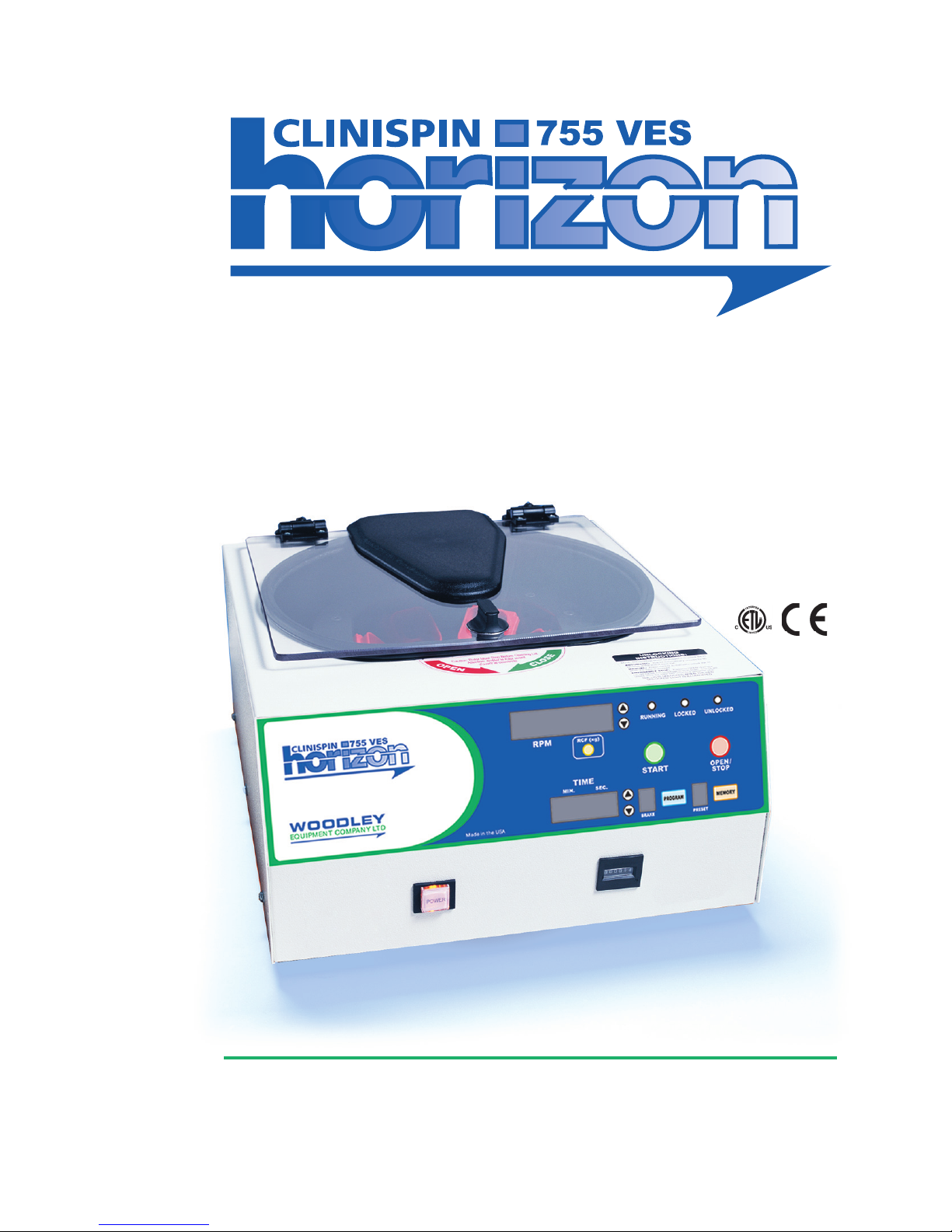
CLINISPIN HORIZON 755VES Laboratory Centrifuge
Rev. 1.3
P/N 7711037

Table of Contents
Model Description page 3
Supplied Equipment page 3
Warranty Information page 3
Specications page4
Control Panel / Parts of the Centrifuge page 5
Setup Location page 6
Initial Setup Procedure pages 6,7
Operation page 7
RotorCongurations
Horizontal Rotor page 8
6-Place 50mL Fixed-Angle Rotor page 8
20-Place Fixed Angle Rotor page 9
Control Panel Functions
Time Adjustment and Timer Operation page 10
Speed Adjustment / RCF Display page 10
Starting and Stopping a Run page 10
Unlocking the Lid page 10
Advanced User Settings
Acceleration Rate page 10
Braking Rate page 11
Countdown Delay page 11
Imbalance Detection page 11
Audible Setting page 11
Memory Locations / Storing and Recalling page 12
Mechanical Cycle Counter page 12
Care and Preventative Maintenance page 13
Troubleshooting page14
Safety page 15
Emergency Rotor Chamber Entry page 15
Calibration and Earth Ground Testing page 15
Replacement Parts page 16
page 2
WARNING: For the safety of both the operator and service
personnel, care should be taken when handling substances that are known to be toxic, radioactive
or contaminated with pathogenic microorganisms when using this centrifuge. When Risk Group II
materialsareused(asidentiedintheWorldHealthOrganization“LaboratoryBio-SafetyManual”),
a Bio-Seal should be employed. More than one level of protection must be provided in the case of
materialsofahighergroup.Theuseofammableorexplosivematerialsaswellasthosematerials
which chemically react vigorously is prohibited.
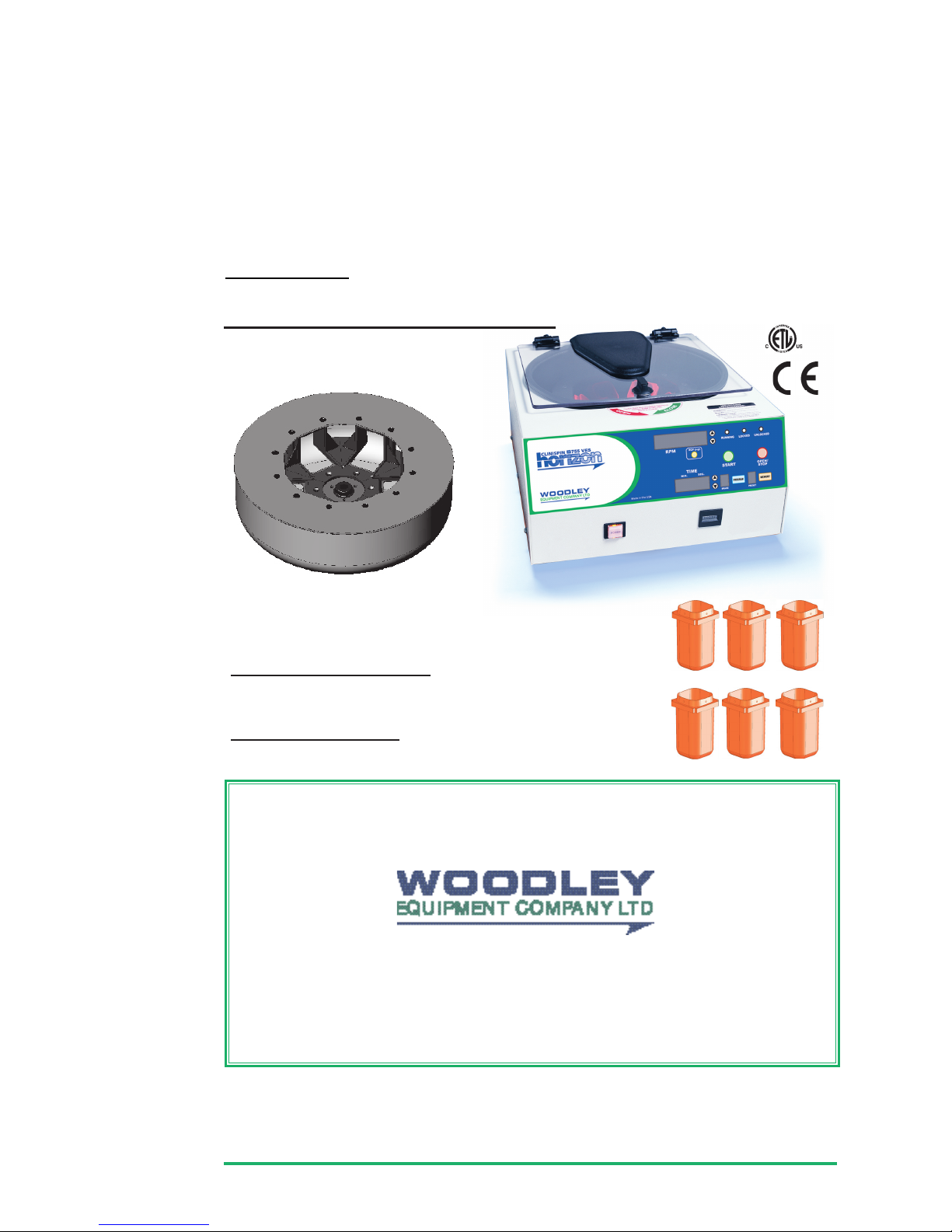
SUPPLIED ACCESSORIES (Standard)
One(1)6-Carrier
Horizontal Rotor*
Also included (not shown):
•One(1)MainsLead•One(1)Operator’sManual
Six(6)
60mL Carriers*
page 3
Available Accessories:
• 6-Place Carrier, for tubes up to 17mm x 125mm • 30-50mL Carrier
WARRANTY:
Woodley Equipment Company warranties that this centrifuge is free from
defects in workmanship and parts for 12 months.
Old Station Park Buildings
St. John’s Street, Horwich
Bolton BL6 7NY, United Kingdom
Tel: +44 (0) 1204 669033 • Fax: +44 (0) 1204 669034
www.woodleyequipment.com Email: sales@woodleyequipment.com
Made in the USA
•Therotorandrotoraccessoriesareratedforarotationalspeedof3500RPM(aforceof2200xg).
Intended Use:
General purpose laboratory centrifuge for sample separation.

Maximum Speed: 3500 RPM
Maximum Force (RCF): 2200 xg
Overall Dimensions (H x W x D): 23x37x43cms
Centrifuge Motor: 1/2 H.P. Brushless DC
Protection Breaker: 4Amp.re–settable
Timer: electronic, with hold
or 0 to 99 minutes, +/- 1%
Weight: 17.7 kgs
Permitted Environmental Conditions
Ambient Temperature During Operation: 2 oC - 35 oC
Maximum Relative Air Humidity: 90%
Electrical Requirements:
Power: 200 Watts
Voltage: North America: 115Volts(+/-10%)
Japan: 100Volts(+/-10%)
Europe: 230Volts(+/-10%)
Frequency: 50/60 Hz
Any use other than those specied by the Manufacturer is explicitly prohibited. Maximum sample density is 1.15 grams / mL,
(waterdensity=1.0grams/mL)*See label on rear of centrifuge for voltage requirements.
SPECIFICATIONS:
Specications for the Clinispin Horizon 755VES Centrifuge
page4
PART NO. # MAX TUBE SIZE SPEED RANGE FORCE RANGE
6-Carrier Horizontal (Standard)
7786022 Comes with your choice of 6 of the holders listed
w/4-Place Carrier 7713023 24 17mm x 100mm 500 to 3,500 RPM 40 to 2,200 xg
w/4-Place Carrier 7713023 12 17mm x 125mm 500 to 3,500 RPM 40 to 2,200 xg
w/50mL Hor. Carrier 7713037 6 34mm x 115mm 500 to 3,500 RPM 40 to 2,200 xg
6-Place 50mL Fixed-Angle 7786044 Comes with 6 of the holders listed
w/50mL Fixed-angle holder 7787051 6 34mm x 125mm 500 to 4,000 RPM 40 to 2,000 xg
20-Place Fixed-Angle 7786042 Comes with 20 of each of the holders listed
w/75mm tube holder 7713043 20 17mm x 75mm 500 to 4,000 RPM 40 to 1,700 xg
w/100mm tube holder 7713040 20 17mm x 100mm 500 to 4,000 RPM 40 to 1,900 xg
w/125mm tube holder 7713044 20 17mm x 125mm 500 to 4,000 RPM 40 to 2,000 xg
12-Place Horizontal 7786024 Comes with 20 of each of the holders listed
w/75mm tube holder 7713043 20 17mm x 75mm 500 to 3,200 RPM 40 to 1,240 xg
w/100mm tube holder 7713040 20 17mm x 100mm 500 to 3,200 RPM 40 to 1,540 xg
w/125mm tube holder 7713044 20 17mm x 125mm 500 to 3,200 RPM 40 to 1,830 xg
75 mm Tube
Holder
p/n 7713043
100 mm
Tube Holder
p/n 7713040
125 mm
Tube Holder
p/n 7713044
Tube Holder Cap
p/n 7713011
50mL
tube holder
xed-angle
p/n 7787051
4-Place Carrier
p/n 7713023
50mL Carrier
p/n 7713037
Carrier
Cap
p/n
7713035

page 5
CONTROL PANEL / PARTS OF THE CENTRIFUGE:
Lid Knob
Lid
Lid Safety
Interlock System
Control Panel
(see below)
Cycle Counter
Power Button
Up/Down RPM
Change Buttons
RPM Display
Running
Indicator
Light
Locked
Indicator
Light
Unlocked
Indicator
Light
Start Button
Open / Stop
Button
Up/Down Time Change Buttons
Time Display

SETUP LOCATION:
1. Unpack the centrifuge and verify that all of the supplied equipment is present.
2. Choose a setup location which meets the following criteria:
a) Abenchtopclearanceheightof51cms”isrequiredinordertoopenthelid.
b) Theclearanceenvelopeisthespacearoundthecentrifugewhichisrequiredfor
safety. Choose a setup location which will allow for a clearance envelope of at least
76x76cms,(withthecentrifugeatthecenter).Nopersonorhazardousmaterialshall
be permitted in the clearance envelope during operation. The operator time within
the envelope shall be limited to the time necessary for loading, unloading and
centrifuge operation only.
c) Properventilationisnecessarytopreventtheoverheatingofsamplesaswellas
premature failure of the centrifuge. Choose an area which will allow unencumbered
airow.
d) Thecentrifugeisdesignedtorestonitsfourrubberfeet.Noadjustmentisnecessary
forlevelingthecentrifuge,however,thesurfaceshouldbeatandlevel.
e) Be sure the outlet is always within reach as the mains lead is the means of
emergency disconnection!
INITIAL SETUP PROCEDURE: If any problems are found during the initial setup
procedure, refer to the troubleshooting section. For further assistance, contact Woodley
Equipment Company. +44 (0) 1204 669033.
1. Plug the female end of the mains lead into the rear of the centrifuge. Plug the male end into
an approved electrical outlet. For electrical safety, the unit must always be properly
grounded.
2. Engagethepowerbuttononthefrontofthecentrifuge(ifitisnotalreadyengaged).The
power button is engaged when it is illuminated.
3. For operator safety, the locking system is always active; requiring power and direction
from the user to disengage it (the lid also automatically unlocks at the end of a run when
itissafetodoso).Tounlockthelid(inordertoaccesstherotorchamber)pressthe
‘OPEN/STOP’buttononthecontrolpanel.The‘UNLOCKED’indicatorlightshould
illuminate. If it does not, refer to the section on troubleshooting. The lid will remain
unlockedfor15secondsafterpressingthe‘OPEN/STOP’button.
4. TurntheLockcounterclockwiseandopenthelid.
5. Spin the rotor by hand; check for free and level rotation. If the rotor does not spin freely,
refer to the section on troubleshooting.
6. Place the test tube carriers into the rotor and verify that they are seated properly.
7. Close the lid. Rotate the lid knob clockwise to its complete stop position. The
’LOCKED’indicatorlightshouldbeilluminated.Ifitisnot,makesurethatthelidis
latched properly. The centrifuge will not run unless the lid is latched properly and the
’LOCKED’indicatorlightisilluminated.
8. Initiateatestrunbypressingthe‘START’button.
9. The‘RUNNING’indicatorlightwillilluminateandthecyclecounterwillincrementbyone.
10. The test tube carriers will slide up into the horizontal position and the unit will accelerate
to the current set speed.
11. Listen to the sound of the centrifuge. A smooth whirring sound should be heard. If there
areanyloudorunusualsounds,stopthecentrifugebypressingthe’OPEN/STOP’button
immediately and refer to the section on troubleshooting.
(continuedonnextpage)
page 6

OPERATION:
NOTE: Follow the initial setup procedure before initial operation.
1. Pressthe‘OPEN/STOP’buttontounlockthelidandthenopenthelid.
2. Place the test tube samples into the tube carriers. Be sure to follow the rules for
balanced loads.
3. Close the lid and turn the lid knob clockwise to its complete stop position. The
LOCKED’indicatorlightshouldilluminatetoindicatethatthelatchisclosed
properly.Ifthelidknobisnotcompletelylatched,the‘LOCKED’indicatorlightwillnot
illuminate and the centrifuge cannot be operated.
4. Setthedesiredspeedandruntimeusingtheappropriateupanddownarrowbuttons.
5. Begintherunbypressingthe‘START’buttononthecontrolpanel.
6. Thecentrifugeshouldbegintospin.The‘RUNNING’indicatorlightshouldilluminate.
IF A PROBLEM IS FOUND DURING A SPIN THAT REQUIRES THE CENTRIFUGE
TO SHUT DOWN, PRESS THE ‘OPEN / STOP’ BUTTON IMMEDIATELY !
7. Aftertimehaselapsed,the‘RUNNING’indicatorlightwillextinguishandtherotorwill
decelerate to a complete stop.
8. The‘UNLOCKED’indicatorlightwillilluminateandthelockingmechanismwill
disengage, allowing entry into the rotor chamber. If the automatic unlock times out
after60seconds)simplypressthe‘OPEN/STOP’button.
9. Turn the lid knob counterclockwise and open the lid.
10. Remove the samples.
11. The centrifuge may be used immediately.
INITIAL SETUP PROCEDURE (continued):
12. Pressthe‘OPEN/STOP’buttontoterminatethetestrun.Therotorwilldeceleratetoa
completestopandthelidwillthenunlockautomaticallyforsixty(60)seconds.
13. The centrifuge is now ready for operation.
page 7

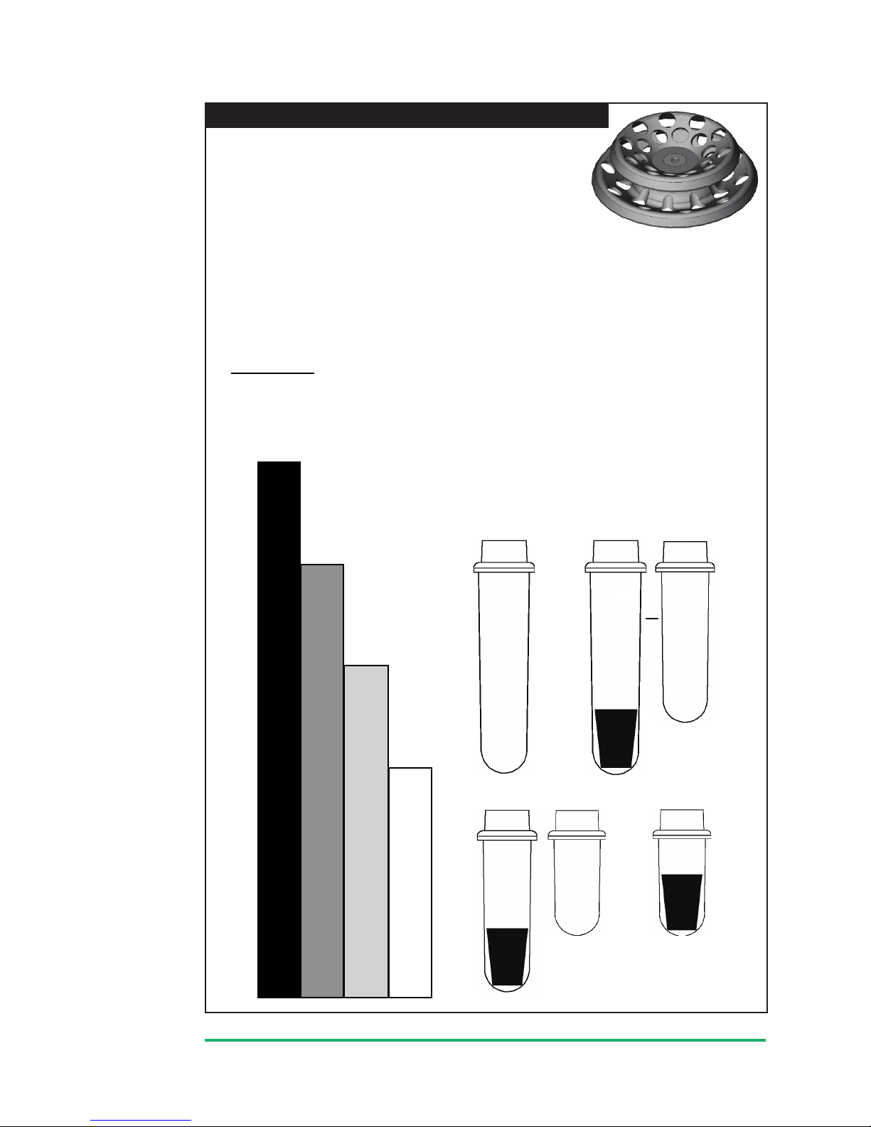
ROTOR CONFIGURATIONS:
1. Opposing tube carriers must be identical.
2. Opposing tube carriers must be empty or loaded with an equal number of
equally weighted samples.
3. If an odd number of samples is to be spun, use a water-lled tube to mate
with the unpaired one.
Your centrifuge must contain a balanced load in order
to work properly. To ensure that the load is balanced,
keep these rules in mind when inserting test tube
samples into the four (6) position horizontal rotor:
This rotor is designed to hold up to 6 tube carriers.
Follow the procedure below for proper tube loading.
page 8
1. Opposing tube carriers must be identical.
2. Opposing tube carriers must be empty or loaded with an equal number of
equally weighted samples.
3. If an odd number of samples is to be spun,
use a water-lled tube to mate with
the unpaired one.
NOTE: Do not load more than two (2) tubes per carrier if the tubes are greater than
100mm long (15mL). When loading these tubes into the carriers, place them all
on either side. For example, to load twelve (12) 15mL tubes, place two tubes on
the right-hand side of each carrier.
WARNING: When using glass test tubes, place a 7mm cushion at the bottom of each
location in the carriers. Failure to do so may result in damage to the test tube.
Six (6) Place 50mL Fixed-angle Rotor (optional):
Your centrifuge must contain a balanced load in order to
work properly. To ensure that the load is balanced, keep
these rules in mind when inserting test tube samples into
the 6 place, 50mL xed-angle rotor:
1. Opposing tube holders must be identical.
2. Opposing tube holders must be empty or loaded equally weighted samples.
3. If an odd number of samples is to be spun, use a water-lled tube to mate
with the unpaired one.
4. (Four Position Carriers Only):
When loading tubes into opposing
carriers, the carriers will be
balanced when the tubes are loaded
diagonally from one another
(not across from one another).
For example: six tubes are to be loaded
into two carriers. In each carrier, two tubes
are placed in the bottom and one tube is
placed in the upper left-hand position.
See picture at right.
Thisrotorisdesignedtoholduptosix(6)50mLtubeholders.
Six (6) Carrier Horizontal Rotor (standard):
page 9
75mm Tube Holder
with
1525 cushion
75mm
Tube
Holder
100mm
Tube
Holder
125mm
Tube
Holder
with
1525
cushion
B1. B2.
or
D.
ORANGE PURPLE
BLUE BLUE
C1. C2.
B.
C.
D.
A.
100mm
Tube
Holder
with
1525
cushion
A.
125mm
Tube
Holder
PURPLE
For Example: A tube is found to be as long as box B. Accordingly, we can
use a 125 mm tube holder with a 1525 cushion or a 100mm tube holder
with no cushion, (congurations B1 or B2).
Thisrotorisdesignedtoholduptotwenty(20)tubeholders.
It comes with three tube holder types. The orange holders are
designedtoholdtubesupto15mL(upto17mmx125mm).The
purple holders are designed to hold tubes up to 10mL
(upto17mmx100mm).Theblueholdersaredesignedtohold
tubesupto5mL(upto17mmx75mm).
Your centrifuge must contain a balanced load in order to work properly. To ensure
that the load is balanced, keep these rules in mind when inserting test tube samples
into the 20 place xed-angle rotor:
1. Opposing tube holders must be identical.
2. Opposing tube holders must be empty or loaded equally weighted samples.
3. If an odd number of samples is to be spun, use a water-lled tube to mate
with the unpaired one.
DIRECTIONS:
1. Compare the tube to be spun with the four boxes shown below.
2. Findtheboxthatmostcloselymatchesthetube’slength.NOTE: The tube length with
its stopper or cap must be shorter then the chosen box.
3. Matchtheletterfromthechosenboxwithoneofthecongurationsshown.
Twenty (20) Place Fixed-angle Rotor (optional):
ORANGE

CONTROL PANEL FUNCTIONS:
Time Adjustment and Timer Operation
The run time may be set from 30 seconds to 99 minutes and 30 seconds.
Press the up and down arrow buttons next to the time display to change the run time. Adjustments
may be made prior to a run or after a run begins. A quick tap will adjust the time by 30 seconds.
Hold down the button for 1 minute adjustments - continue to hold for 5 minute adjustments.
Pressthedownbuttononcewhile00:30isdisplayedtoaccessthe“hold”feature.Whena“hold”
run is initiated, the timer will count up to keep track of total run time. The unit will run for a maximum
of99minutesand30secondsandwillthenshutoffautomatically.The“hold”runmayalsobe
terminatedbypressingtheSTOP/OPENbutton.Thetotalruntimeduringa“hold”runisdisplayed
on the time display until the operator unlocks the lid by pressing the OPEN button or opens the lid
(duringtheautomaticunlockaftertherunends).
Speed Adjustment/ RCF Display
Press the up and down arrow buttons next to the speed display to change the run speed.
Adjustments may be made prior to a run or after a run begins. A quick tap will adjust the speed
by 50 RPMs. Hold down the button for 100 RPM adjustments. Continue to hold for 500 RPM
adjustments.
Press the RCF button at any time to convert the current speed setting to the corresponding force
value(xg).ThespeedmaybesetbyRCFbyholdingdowntheRCFbuttonwhileusingtheup/down
speed set buttons. The jumps made in the RCF value while holding down the RCF button and
pressing the up and down arrow buttons correspond to 50 RPM adjustments in speed. Since the
RCF is a function of the square of the speed, this jump size will vary.
Starting and Stopping a Run
With the lid switch closed, press the START button to begin a run.
Press the STOP/OPEN button at any time during a run to terminate it.
Unlocking the Lid
ThelidisunlockedwhenevertheredUNLOCKEDindicatorlightisilluminated.Thelidunlocks
automatically for 60 seconds at the end of a run. The lid can also be unlocked for an additional 15
seconds by pressing the OPEN/STOP button while the unit is idle. The lid cannot be unlocked while
the rotor is spinning.
Imbalance Detection
This centrifuge is equipped with imbalance detection. If an imbalance is detected, the centrifuge will
terminatethecurrentrunandwillbegintobraketoastop.Thewords“BALANC”and“ERROR”will
ashonthespeeddisplay.Oncetherotorhasstopped,openthelidtocanceltheerrorreporting,
balance the load and begin a new run. Alternately, the error reporting can be canceled by pressing
the OPEN/STOP button.
Advanced User Settings:
This centrifuge allows for total control of the run by the user. You may adjust the acceleration rate,
adjust the braking rate, adjust the imbalance sensitivity level, select from several audible settings,
and use the optional countdown delay.
Acceleration Rate - Theusermayadjusttheaccelerationratefromminimum(1)tomaximum
(10)usingthefollowingprocedure:
1. While the centrifuge is idle, press the PROGRAM button.
2. UsetheUP/DOWNarrowbuttonsnexttothespeeddisplayuntil“ACCEL”is
displayed in the speed display.
3. The current acceleration rate is displayed in the time display. Use the ‘UP/
DOWN arrow buttons next to the time display to adjust the acceleration rate
from1(minimum)to10(maximum).
4. PressthePROGRAMbuttontoexitorusetheUP/DOWNarrowbuttonsnextto
the speed display to adjust additional settings.
page 10

Advanced User Settings (continued):
Braking Rate - Theusermayadjustthebrakingratefromminimum(slowestdeceleration,0)to
maximum(quickestdeceleration,9)usingthefollowingprocedure:
1. While the centrifuge is idle, press the PROGRAM button.
2. UsetheUP/DOWNarrowbuttonsnexttothespeeddisplayuntil“BRAKE”is
displayed in the speed display.
3. The current braking rate is displayed in the brake display. Use the UP/DOWN
arrow buttons next to the brake display to adjust the braking rate from 0
(minimum)to9(maximum).
4. PressthePROGRAMbuttontoexitorusetheUP/DOWNarrowbuttonsnextto
the speed display to adjust additional settings.
Countdown Delay - When the countdown delay is turned on, the timer will not begin
decrementing until the rotor has reached full speed as set by the user. This feature ensures that the
samples see full force for the total run time.
1. While the centrifuge is idle, press the PROGRAM button.
2. UsetheUP/DOWNarrowbuttonsnexttothespeeddisplayuntil“CNTDLY”is
displayed in the speed display.
3. Thecurrentstatusofthisfeature(ONorOFF)isdisplayedinthetimedisplay.
Press UP/DOWN arrows next to the time display to toggle the status between
ON and OFF.
4. PressthePROGRAMbuttontoexitorusetheUP/DOWNarrowbuttonsnextto
the speed display to adjust additional settings.
Imbalance Detection - This centrifuge is equipped with imbalance detection. This ensures that
the centrifuge will safely shut down in the event that an imbalanced load is run or a malfunction
occurs. This feature is intended to provide for operator safety and to extend the life of the
centrifuge. The LOW setting will allow for a greater imbalance before shutting the centrifuge down.
1. While the centrifuge is idle, press the PROGRAM button.
2. UsetheUP/DOWNarrowbuttonsnexttothespeeddisplayuntil“BALANC”is
displayed in the speed display.
3. Thecurrentstatusofthisfeature(LOWorHI)isdisplayedinthetimedisplay.
Press UP/DOWN arrows next to the time display to toggle the status between
LOW and HI.
4. PressthePROGRAMbuttontoexitorusetheUP/DOWNarrowbuttonsnextto
the speed display to adjust additional settings.
Audible Settings - The user may select from six different audible indicator levels:
Setting ButtonPressBeep? End-of-runaudiblenotication
1 NO NONE
2 YES NONE
3 NO YES, 5 beeps
4 YES YES,5beeps
5 NO YES, continuous, user must press STOP/OPEN button to cancel
6 YES YES, continuous, user must press STOP/OPEN button to cancel
1. While the centrifuge is idle, press the PROGRAM button.
2. UsetheUP/DOWNarrowbuttonsnexttothespeeddisplayuntil“BEEPER”is
displayed in the speed display.
3. The current audible selection is displayed in the time display. Use the UP/
DOWNarrowbuttonsnexttothetimedisplaytoselectasetting(1to6).
4. PressthePROGRAMbuttontoexitorusetheUP/DOWNarrowbuttonsnextto
the speed display to adjust additional settings.
page 11

TheClinispinhorizon755VEScentrifugeiscapableofstoringupto10user-denedpresets.
Thesememorypresetscontainallofthesettingsneededtodeneaspecicrun,(runtime,speed,
accelerationrate,brakingrate,etc.).Theusercanusethesememorylocationstoquicklycongure
thecentrifugeforaspecictesttypeandensurethatthetestisruninthesamewayeachtimeby
recalling this same setting.
Store a conguration in a memory location
1. Adjustthevarioussettings(speed,time,accelerationrate,etc.)forthe
congurationtobesaved.
2. PressandholdthePROGRAMbuttonuntilthepresetdisplaybeginstoash.
3. Press the MEMORY button to increment the memory location by one. Continue
to press the memory button until the desired location is displayed.
4. Presstheprogrambuttontostorethecurrentcongurationintothememory
location that is displayed.
Recall a conguration from a memory location
1. Press the MEMORY button until the desired memory location is displayed in the
memory display.
2. As you review the presets, the settings on the control panel will change to
reectthesettingsstoredinthememorypresetcurrentlydisplayed.
3. When the desired preset is found, pause and the memory display will
momentarilyash.Thestoredcongurationisnowloaded.
Notes:
Onceacongurationhasbeenloaded,itwillremainactiveuntilanychangeismadeonthecontrol
panel.Ifforinstancetheuseradjuststhetime,thecurrentcongurationwillnolongermatchthe
previouslyloadedcongurationandthememorydisplaywillchangetoa“-”dash.Theprevious
congurationmayberecalledusingtheproceduredescribedabove.
Memory locations may be overwritten by selecting them during the store procedure.
Cycle Counter:
This centrifuge is equipped with a mechanical cycle counter to monitor machine usage and for
routine maintenance. The cycle counter is located on the front of the centrifuge.
Memory Locations / Storing and Recalling:
page 12

CARE AND PREVENTATIVE MAINTENANCE:
With proper care and maintenance your Horizon centrifuge will provide years of laboratory service.
For proper care, the following steps should be taken:
1. Provide Adequate Ventilation: For cooling purposes, the Horizon draws in ambient air
through the air intake cover on the top of the lid and exhausts this air in the rear of the base.
The centrifuge should be placed on a hard smooth surface for good air circulation.
2. Always Spin Balanced Loads: This centrifuge is equipped with imbalance detection.
However, it is still possible to run loads that are minimally imbalanced. Refer to page 8 on
balanced loads for additional information on balancing the load.
3. Keep the Tube Carriers / Holders Clean: NOTE: Always follow the safety guidelines of
your laboratory to properly clean up and/or dispose of materials in the event that a
substance known to be potentially toxic, radioactive or contaminated with a pathogenetic
microorganism is spilt in or on the centrifuge. Small glass fragments left in the tube carrier
/ holder after a tube breakage may adhere to the next test tube inserted in that carrier /
holder. When this tube is handled, these fragments may puncture protective gloves and
laceratetheoperator’sngersorhand.Remainingfragmentsmayprovidestresspoints
on subsequent tubes and result in additional breakage. If a tube breakage occurs,
carefully remove the tube holder. Properly dispose of the sample and tube fragments and
thoroughly clean both the inside and outside of the tube carrier / holder. Insert a new tube
cushion(ifnecessary)andreplacethetubecarrier/holderintherotor.
4. Motor and Electrical Maintenance: This centrifuge uses a brushless-DC motor. There
are no brushes to replace and it should not need routine servicing for the life of the
centrifuge. The electrical components are selected for high reliability and should not need
service.
5. Keep the Centrifuge Clean: The cabinet, rotor top and accessories shall be thoroughly
cleaned using either isopropyl alcohol, soap and water, or a mild bleach solution. The use
ofFully/PartiallyHalogenatedHydrocarbons,Ketones,Estersandallotherchemicalsnot
prescribed by the manufacturer may cause damage to the rotor and tube carriers / holders
and should not be used.
Ifitisnecessarytoremovetherotorforadditionalcleaningitisrequiredthataqualied
technician remove the outside housing and rotor assembly. Contact Woodley Equipment
Company for additional information.
Apply cleaning solutions with a towel or cloth. Do not submerge the centrifuge in water or
other cleaning solutions as this will cause damage and void your warranty!
6. Tube Carrier / Holder Replacement: Tube carriers are stamped with an expiration date and
should be replaced according to this stamp.
page 13

TROUBLESHOOTING:
1. Problem: The rotor does not spin freely.
Solutions: • Make sure that nothing has fallen into the rotor chamber.
• If there is nothing obstructing the rotor, the motor may be damaged.
Contact your authorized dealer or Woodley Equipment Company for further
assistance.
2. Problem: There is excessive noise when the machine is running.
Solutions: • Check to see that the load is balanced.
• Make sure that nothing has fallen into the rotor chamber.
• Make sure that the screw in the center of the rotor is snug.
• The motor may be damaged. Contact your authorized dealer or
Woodley Equipment Company for further assistance.
3. Problem: The centrifuge does not run or an error message is displayed.
Solutions: • Make sure that the centrifuge is getting power. Do the control panel
displays come on? Check the electrical outlet that the unit is plugged into.
Check the circuit breaker on the base near the rear of the centrifuge.
• If the unit is getting power, make sure that the lid latch is closed properly.
Thelatchisclosedproperlywhentheyellow‘LOCKED’indicatorlightis
illuminated.
•Ifthecentrifugestopssoonafterstart-upand‘ERROR’isdisplayedonthe
speed display, refer to the following table for fault information:
ERROR / SPEED
The centrifuge cannot reach full speed due to a problem with the rotor, an
inadequate power supply, or other electrical problems. Press the OPEN/
STOP button to cancel the error and then check the rotor and the line
voltage. Contact your authorized dealer or Woodley Equipment Company for
further assistance.
ERROR / BALANC
The centrifuge has detected an imbalance. Press the OPEN/STOP button to
cancel the error and balance the load. If the load is balanced, make sure
that the centrifuge is installed on a secure, level location.
4. Problem: The lid knob cannot be turned / the lid cannot be unlocked.
Solutions: • Make sure the centrifuge has power and that the rotor is stopped. Press the
‘OPEN/STOP’button.Thered‘UNLOCKED’indicatorlightshouldilluminate
and the unlocked mechanism should disengage, allowing entry into the
rotor chamber.
•Ifthelidisstilllocked,makesurethatthered‘UNLOCKED’indicatoris
illuminatedandturnthelidknobrstcompletelyclockwiseandthen
counterclockwise.
•Ifthered‘UNLOCKED’indicatorwillnotilluminateorthelocking
mechanism will not disengage, the electronics or locking mechanism may
be damaged. Have a technician service the centrifuge or contact Woodley
Equipment Company for further assistance.
page14
For additional assistance, services and technical support
contact Woodley Equipment Company LTD.

SAFETY:
Horizon Lid Safety Switch: The Horizon lid is secured to the top of the cabinet by a latching
knob and pawl system. When the knob is rotated clockwise, the pawl grips the underside of the
cabinet opening and prevents the lid from opening. A mechanical stop positions the pawl and
prevents it from rotating completely. When rotated to the stop position, the pawl makes contact
withamicro–switchmountedunderneaththecabinettop.Thelidsafetyswitchpreventsthe
centrifugefromoperatingwhilethelidisopen.Theyellow‘LOCKED’indicatorlightonthefrontof
the machine will illuminate when the lid has been latched properly.
Horizon Lid Safety Interlock System: In addition to the Lid Safety Switch, the Horizon has a
true“0RPM”lidlockingsystem.Thelidsafetyinterlocksystemkeepsthelidlockedatalltimes,
(evenduringpowerfailure),andrequiresthattherotorbeatrestinordertounlockthelid.The
centrifuge will not allow entry into the rotor chamber unless the centrifuge has power and the rotor
is stopped. To open the lid, make sure that the centrifuge is plugged in and, with the rotor stopped,
pressthe‘OPEN/EMERGENCYSTOP’button.
Note: After the centrifuge has started spinning, it may be possible to rotate the lid knob
enough to cause the pawl to lose contact with the lid safety switch. If this happens, the
centrifuge motor may lose power, but the lid will still remain locked. If the knob is accidentally
moved and this situation should occur, rotate the knob fully clockwise to its stop position and
the centrifuge will resume operation.
Circuit Breaker: TheHorizonisprotectedwitha4Ampcircuitbreakerlocatedattherearofthe
machine mounted to the base. Any electrical short circuit will cause the breaker to cut power to the
machine.
Calibration and Earth Ground Testing:
It is recommended that the top speed, ground continuity and line leakage be tested every two
years for continued safe operation. Contact Woodley Equipment Company. for further information
or testing availability.
Emergency Rotor Chamber Entry:
In the event of power failure, it may be impossible to unlock
the lid by conventional means. In this case, entry into the rotor
chamber may be made by removing the latch label and using
a pen to manually disengage the locking mechanism (see
photo).Pullthemechanismtowardsthecontrolpanelandthen
unlatch and open the lid. If the unit is damaged, contact your
authorized dealer or Woodley Equipment Company.
page 15
The Clinispin Horizon 755VES complies with all requirements of CE EN 61000-3-2, -3-3, EN
61000-4-2, -4-3, -4-4, -4-5, -4-6, -4-11, EN 61010-1, -2-020 and UL standard 3101–2–20, Can/
CSA C22.2 No. 1010.1 , Can/CSA C22.2 No. 1010.2.20

Made in the USA
Contact your authorized dealer or Woodley Equipment Company
to order replacement parts or accessories.
Old Station Park Buildings
St. John’s Street, Horwich
Bolton BL6 7NY, United Kingdom
Tel: +44 (0) 1204 669033 • Fax: +44 (0) 1204 669034
www.woodleyequipment.com Email: sales@woodleyequipment.com
Replacement Parts:
Part No. Description
7728052 Foot, rubber
7751068 Lid Tray Micro-Switch
7723002 Lid Tray Solenoid
7735016 Motor, 1/2 H.P. Brushless DC
7717041 PCControlBoard
3056001 Step Down Transformer
7751043 CircuitBreaker
7724149 FrontPanelLabel
7760003 Mains lead
7714101 Pawl,lock,lid
7714103 Knob,lock,lid
7712263 Lid
7724071 Hinge,friction
7732018 Gasket, cabinet opening
7732019 Gasket, rotor chamber
125 mm
Tube Holder
p/n 7713044
Tube
Holder Cap
p/n 7713011
75 mm
Tube Holder
p/n 7713043
100 mm
Tube Holder
p/n 7713040
20-Place
Fixed-Angle Rotor
p/n 7786042
4-Place
Carrier
p/n 7713023
50mL
Carrier
p/n 7713037
Carrier Cap
p/n 7713035
6-Carrier
Horizontal
Rotor
p/n 7786022
50mL
tube holder
xed-angle
p/n 7787051
6-Place 50mL
Fixed-Angle Rotor
p/n 7786044
250mm Tube
Cushion
p/n 1525
7mm Tube
Cushion
p/n 9150
Table of contents
Other Clinispin Horizon Laboratory Equipment manuals


