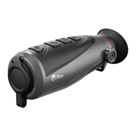
InfiRay MINI MH25 V2 User manual

INFIRAY OUTDOOR
MINI MH25V2
Multi-function Thermal Imager
User’s Manual
Outdoor

1
WARNING!
ITAR REQUIREMENTS
These products may be subject to export and foreign trade control laws of
the United States and may not be exported without prior approval of the
U.S. Department of State. Learn more at irayusa.com/ITAR.
FCC ID: 2AYGT-24-00
This device complies with part 15 of the FCC Rules. Operation is subject to the following two
conditions: (1) This device may not cause harmful interference, and (2) this device must accept
any interference received, including interference that may cause undesired operation.
CAUTION: Changes or modifications not expressly approved by IRayUSA could void the
user’s authority to operate the equipment.
NOTE: This equipment has been tested and found to comply with the limits for a Class
B digital device, pursuant to part 15 of the FCC Rules. These limits are designed to
provide reasonable protection against harmful interference in a residential installation.
This equipment generates, uses and can radiate radio frequency energy and, if not
installed and used in accordance with the instructions, may cause harmful interference
to radio communications. However, there is no guarantee that interference will not occur
in a particular installation. If this equipment does cause harmful interference to radio or
television reception, which can be determined by turning the equipment o and on, the
user is encouraged to try to correct the interference by one or more of the following
measures:
• Reorient or relocate the receiving antenna.
• Increase the separation between the equipment and receiver.
• Connect the equipment into an outlet on a circuit dierent from that to which the
receiver is connected.
• Consult the dealer or an experienced radio/TV technician for help.
This device was tested for typical body-supported operations and use. To comply with RF
exposure requirements, a minimum separation distance of 0.5cm must be maintained between
the user’s body and the handset, including the antenna. Third-party belt-clips, holsters,
and similar accessories used by this device should not contain any metallic components.
Body accessories that do not meet these requirements may not comply with RF exposure
requirements and should be avoided. Use only the supplied or an approved antenna.
TABLE OF CONTENTS
1. Overview ................................................................................ 2
2. Features ................................................................................. 2
3. Tech Specs .............................................................................. 3
4. Accessories ............................................................................. 4
5. Components and Controls ...................................................... 5
6. Quick Start Guide.................................................................... 6
7. Installing the Battery ...............................................................7
8. Charging the Battery............................................................... 8
9. Removing the Battery.............................................................. 8
10. Battery Safety Warnings ......................................................... 9
11. External Power Supply ...........................................................10
12. Mounting the MH25V2 to a Helmet ......................................10
13. Operating Instructions ............................................................11
14. Non‑uniformity Correction ..................................................... 17
15. Photography and Video Recording ........................................ 18
16. Accessing the Internal Memory............................................. 20
17. Using the Bluetooth Remote .................................................. 21
18. Using the InfiRay Outdoor App ............................................. 22
19. Video Output......................................................................... 23
20. Digital Zoom ......................................................................... 24
21. Picture in Picture (PIP).......................................................... 24
22. Stadiametric Rangefinder ..................................................... 25
23. Main Menu Options and Descriptions................................... 26
24. Basic Inspection ................................................................... 35
25. Basic Maintenance ................................................................ 35
26. Warranty ................................................................................ 36
27. General Troubleshooting .......................................................37

2 3
1. OVERVIEW
The InfiRay Outdoor MINI MH25V2 is a compact, lightweight thermal imager
designed for handheld or helmet-mounted use. Its unique design allows for
seamless operation as a handheld monocular, and it can easily transition to a
helmet mount for hands-free use. The MH25V2 is powered by a 50hz 12 μm
sensor and features next-generation MATRIXIII processing for an unmatched
viewing experience. In addition to the features found on the original MH25,
the MH25V2 adds several highly-requested features including an upgraded
AMOLED display, an upgraded eyepiece, and onboard video and audio
recording.
2. FEATURES
• 12 μm high-performance thermal detector
• High image quality
• Aluminum/ABS housing
• Maximum detection range 1375 yards
• Rechargeable battery included
• HD 1280×960 AMOLED display
• High frame frequency: 50hz
• Stepped digital zoom from 1.0×to4.0×
• Built-in 32 GB storage to support
image capture and video recording
• Built-in motion sensor
• Bluetooth remote control
• Built-in Wi-Fi module
• Mobile device App compatible
• Automatic standby
• Multiple color palette options
• Picture in Picture (PIP)
• User-friendly interface
3. TECH SPECS
MINI MH25W
SENSOR
Resolution 640×512
Pixel Size 12 μm
Frame Rate 50hz
Image Processing MATRIX III
Core InfiRay Micro II 640
OPTICS
Objective Lens 25 mm f/1.0
Magnification 1×
Digital Zoom 4×, Stepped
Field of View 17.5° × 13.1°
Detection Range 1375 Yards
Display Type AMOLED
Display Resolution 1280×960
Color Palettes White Hot, Black Hot, Red Hot, Color
Mounting System MUM Rail
P.I.P. Ye s
Rangefinder Stadiametric
Eye Relief 20 mm
Diopter Range -4 to +3
ELECTRONICS
Onboard Recording Video and Image
Onboard Storage 32 GB
Data Connector USB-C, Analog Video Out
Data/Power Connector USB-C
Power Supply USB-C External, 16340 Battery (1+ Hour), 16650 Battery (2.5+ Hours)
Start Up Time <10 Seconds, Instant from Standby
PHYSICAL
Size 5.03” × 2.75” × 1.77”
Weight 12.1 Oz
ENVIRONMENTAL/WARRANTY
Warranty 5 Years
Housing Material Aluminum/ABS
Ingress Protection IP67
Operation Temperature 14°F~122°F

4 5
4. ACCESSORIES
The MINI MH25V2 thermal imager ships with everything you need to get out
and hunt.
• MINI MH25V2
• Standard Eyeguard for MINI
• Bluetooth Remote Control
• USB-C to Analog RCA/USB Cable 36”
• 16340 Rechargeable Battery
• Micro-USB Cable
• Adapter for 16650 Battery*
• USB Power Adapter
• Soft Case and Shoulder Strap
• Lens Cloth
• User Manual
*16650 battery is optional/not included.
Replacement accessories are available for purchase. Contact 800-769-7125
or irayusa.com/support.
5. COMPONENTS AND CONTROLS
8 9
1 2 3 4 5 6 7
1Objective Lens Cap
2Objective Lens Focus Ring
3Battery Cover
4USB-C Port
5 Rotary Encoder
6Eyepiece / Diopter Adjustment Ring
7Eyeguard
8 MUM Rail Interface
9 Dovetail Interface for Optional IRAY-AC49

6 7
6. QUICK START GUIDE
Step 1: Prepare to Use the MINI MH25V2
1. Compare the box contents to the accessories list and examine each for
any shipping damage. See Accessories on page4.
2. Check the lens to ensure there are no smudges or dirt present. Clean
with the included lens cloth, if necessary.
3. Install the eyeguard (7).
4. Insert the 16340 battery into the battery compartment. See Installing the
Battery on page7.
5. Mount the MH25V2 to a helmet (optional). See Mounting the MINI
MH25V2 to a Helmet on page10.
Step 2: Turn On the MH25V2
1. Open the objective lens cap (1).
2. Long press the Rotary Encoder (5) for 3 seconds to power on the
MH25V2. The InfiRay Outdoor logo will appear.
3. Rotate the diopter adjustment ring (6) of the eyepiece until the interface
icons are clearly visible.
WARNING: Do not point the objective lens toward intense energy
sources, such as the sun. This may render the electronic components
inoperative. The warranty does not cover damage caused by improper
operation.
Step 3: Adjust Image and Device Settings
1. Short press the Rotary Encoder (5) to enter the quick menu to adjust
the following settings (see Using the Quick Menu on page15):
a. Set the color palette to white hot, black hot, red hot, or color.
b. Set the display brightness level, from 1–5.
2. Long press the Rotary Encoder to enter the main menu to adjust the
following settings, as needed:
a. Turn on the motion sensor. See Device Menu > Msensor on
page28.
b. Turn on the PIP window. A 2× zoomed image (2× that of the total
zoom shown in the status bar) will appear at the top of the screen.
See Function Menu > PIP on page30.
c. Set the date and time. See Calibration Menu > Time on
page31.
d. Set the image sharpness level, from 1–4. See Setting Menu >
Sharpness on page33.
e. Set the non-uniformity correction (NUC) mode to automatic or
manual. See Setting Menu > NUC Mode on page33.
3. From the home screen, rotate the Rotary Encoder to zoom in or out,
from 1.0 to 4.0×, in increments of 0.1. The real-time amplification number
appears in the status bar. See Digital Zoom on page24.
7. INSTALLING THE BATTERY
1. Remove the battery cover (3) by turning it counterclockwise.
2. Insert a 16340 battery (or a 16650 battery plus adapter) into the
battery compartment following the polarity markings on the outside
of the compartment. The positive [ + ] battery terminal faces in and the
negative[ − ] terminal faces out
3. Replace the battery cover.

8 9
8. CHARGING THE BATTERY
The MINI MH25V2 thermal imager comes with a 16340 rechargeable lithium-
ion battery which provides 1+ hours of operation. One 16650 rechargeable
li-ion battery (optional/not included) is also compatible with MH25V2 but
requires the use of the included battery adapter.
WARNING: The MINI MH25V2 is ONLY compatible with one 16340
battery or one 16650 battery (with the included adapter). Do NOT use
CR123 batteries or two 16340 batteries at the same time as this will
damage the thermal imager and void your warranty.
Fully charge the battery before using the MINI MH25V2 for the first time:
1. Connect the micro-USB cable to the port on the side of the battery.
2. Connect the standard USB end of the cable to:
a. The included 5V–2A USB power adapter; OR
b. Any standard USB 3.0 port on a laptop or computer; OR
c. An external power supply, such as a USB power bank.
WARNING: The MH25V2 can only be powered by a factory-supplied
16340 battery or a 16650 battery (optional/not included) plus adapter.
Using any other battery may cause irreparable damage to the thermal
imager or cause a fire. Any damage from using an improper battery will not
be covered by warranty.
9. REMOVING THE BATTERY
1. Remove the battery cover (3) by turning it counterclockwise.
2. Remove the 16340 battery.
10. BATTERY SAFETY WARNINGS
WARNINGS:
• Do not use a power adapter or USB cable that has been modified or
damaged.
• Do not expose the battery to high temperatures or flames, and do not
immerse in water.
• Do not leave the battery unattended while charging.
• Do not leave the battery charging for long periods after full charge is
reached. Charging time should not exceed 24 hours.
• Keep batteries out of the reach of children and pets.
• The battery is equipped with short-circuit protection. However, any
situation that may cause short-circuiting should be avoided.
• Do not disassemble, modify, hit, or drop the battery.
• Do not connect the battery to any external device with an electrical
current that exceeds permitted levels.
• Do not connect an external device with a current supply that exceeds
the 3.0 USB port.
To maintain optimal battery capacity and service life:
• Avoid storing a fully charged or discharged battery for long periods.
Partial charging of the battery is necessary if the battery will be stored
for an extended period.
• Do not charge an extremely cold battery without bringing it into a warm
environment. Let the battery warm up for 45 minutes before charging.
• Charge the battery at a temperature range from 32°F to 113°F; otherwise,
the service life of the battery may be reduced.
• The recommended operating temperature range is -4°F to 122°F.
Avoid using the battery above the maximum or below the minimum
recommended temperature as this may decrease the battery capacity
or service life.

10 11
IRAY‑AC49 Mount
Dovetail Interface
Socket Head Screws (2)
2. Insert the two socket head screws included with the dovetail shoe
through the screw holes in the shoe.
3. Tighten until snug. Take care not to damage the threads in the body of
the MH25V2.
4. Finish mounting to your helmet with a compatible dovetail-style bridge
and mount interface.
13. OPERATING INSTRUCTIONS
WARNING!
Do not point the objective lens towards any intense energy sources, such as laser
radiation or the sun. This may render the electronic components inoperative. The
warranty does not cover damage caused by improper operation.
Control Buttons
The MINI MH25V2 features simple, one-button operation via the Rotary
Encoder (5). The MH25V2 may also be operated via the included Bluetooth
remote control. See Using the Bluetooth Remote on page21.
11. EXTERNAL POWER SUPPLY
The MINI MH25V2 supports the use of an external power supply, such as a
5V mobile power bank.
1. Connect the external power supply to the USB-C port (4).
NOTES:
• Always power o the MH25V2 before disconnecting the external
power supply, or data will not be saved.
• Do not connect the MH25V2 to an external device with a power supply
that exceeds the 3.0 USB cable.
12. MOUNTING THE MH25V2 TO A HELMET
The MINI MH25V2 can be mounted to a helmet using the MUM rail interface
or with the optional dovetail shoe (IRAY-AC49).
NOTE: Torque all hardware to a maximum of 15 inch-pounds (in/lbs) unless
noted otherwise. Please note, torque is inch-pounds, NOT foot-pounds. If
you do not have a torque wrench, apply until snug. Do not over-tighten.
No threadlocker is required for proper use; but if you do decide to use a
threadlocker, use only a small amount of low-strength LOCTITE 222.
MOUNTING WITH THE BUILTIN MUM RAIL INTERFACE
Mount the MINI MH25V2 to your helmet with compatible dovetail-style
helmet interface and hardware.
MOUNTING WITH THE OPTIONAL AC49 MINI DOVETAIL SHOE
1. Place the MINI Dovetail Shoe (IRAY-AC49) on the MH25V2 over the
dovetail interface (9) on the bottom of the imager, with the narrow end
of the dovetail facing towards the eyepiece as shown on the next page.

12 13
Power On / Starting
1. Open the objective lens cap (1).
2. Long press the Rotary Encoder for 3 seconds to turn on the thermal
imager. The InfiRay Outdoor logo will appear.
To determine the current battery charge, check the battery icon in the
upper-right corner of the screen. See Battery Status on page15.
Powering O / Stopping
To power o the MH25V2:
1. Point the objective lens down and long press the Rotary Encoder for
3seconds to turn o the thermal imager.
STANDBY MODE
In the main menu, the MH25V2 may be set to automatically enter standby
mode after 5minutes of inactivity.
1. In the main menu, turn on standby mode. See Setting Menu > Standby
on page34 for instructions.
2. Once set, the MH25V2 will automatically enter standby mode after
5minutes of inactivity to conserve battery life.
3. When in standby mode, short press the Rotary Encoder to exit and
return to the home screen.
NOTES:
• The MH25V2 will not enter standby if Wi-Fi, Bluetooth, or video
recording is on.
• When standby is o, the thermal imager will operate until the battery
runs out.
Adjusting the Focus
ADJUSTING THE DIOPTER/EYEPIECE
1. Rotate the eyepiece diopter adjustment ring (6) at the rear of the
thermal imager right or left until the user interface is clear.
2. Look closely to ensure all screen symbols and the status bar appear
sharp and in focus. No additional diopter adjustments are required
unless the user wishes to make changes.
NOTES:
• After the initial adjustment, there is no need to rotate the eyepiece
adjustment ring (6) for long distances or other conditions.
• If necessary during standard use, the objective lens focus ring(2) may
be rotated to adjust fine focus on the target object being observed. See
Focusing the Objective Lens below.
FOCUSING THE OBJECTIVE LENS
To adjust the focus on the target object:
1. Rotate the objective lens focus ring (2) left or right to adjust fine focus
on the target object being observed.
NOTE: Re-adjusting the focus will be necessary if the distance to the
target changes.

14 15
Status Bar Overview
The status bar at the top of the screen shows information on the operating
status of the MINI MH25V2.
1 5 6 73 42
1Color Palette: Shows the color palette icon and selected palette,
white hot(W) , black hot (B), red hot (R), or color (C). White hot is the
default.
2Non‑uniformity Correction (NUC) Mode: Shows the non-uniformity
correction (NUC) icon and selected mode, automatic (A) or manual
(M). Automatic is selected by default.
3Bluetooth: When Bluetooth is turned on, the Bluetooth icon will
appear in the status bar and flash to indicate that the MH25V2 is
ready to connect to the Bluetooth remote control. When successfully
connected, the Bluetooth icon will stop flashing. Bluetooth is o by
default.
4Wi‑Fi: Shows the Wi-Fi icon when on. Wi-Fi is o by default.
5Total Magnification: Shows the real-time magnification, 1.0–4.0×.
6Video Output: Shows the video output icon when on. Video
output is o by default.
7Battery: Shows the current battery status.
BATTERY STATUS
The battery icon color and fill level indicate the current battery status. The
battery icon is replaced by the USB icon when an external power supply is
connected.
COLOR / ICON BATTERY STATUS
Green Battery 41% – 100%
Yellow Battery 20% – 40%
Red Battery <20%; charge the battery right away.
USB External power supply or computer is connected via the data cable.
Using the Quick Menu
In the quick menu, perform a
non-uniformity correction (NUC),
take a photo or video, and set
the color palette and display
brightness.
1. On the home screen, short
press the Rotary Encoder to
enter the quick menu.
2. Rotate the Rotary Encoder
left or right to move through
the menu options below. The icon for the selected menu item turns
blue.
a. (Perform a NUC ): Short press the Rotary Encoder to perform
a manual NUC. If the objective lens is pointed down when the
Rotary Encoder is pressed, a background NUC will be performed.
The device’s internal shutter will not close; the user must manually
close the objective lens cap.

16 17
In all menu interfaces:
• The cursor position in the main menu and submenus is indicated by a
blue back-highlight.
• Short press the Rotary Encoder to move right to left through the four
main menu selections, Device, Function, Calibration, and Setting.
• Rotate the Rotary Encoder to move up or down through the submenu
options.
• In a submenu, short press the Rotary Encoder to change the
parameters for the selected submenu option.
• Long press the Rotary Encoder to confirm any changes and exit to
the home screen. After 15 seconds of inactivity, the MH25V2 will
automatically save any changes and exit to the home screen.
14. NON-UNIFORMITY CORRECTION
A non-uniformity correction (NUC) allows a thermal imager’s sensors to
correct its pixels and eliminate any image defects caused by pixel drift.
A NUC will be performed automatically each time the MINI MH25V2 is
powered on.
The MH25V2 has two NUC modes, automatic and manual. The selected
NUC mode, A or M, appears in the status bar. For instructions on setting the
NUC mode in the main menu, see Setting Menu > NUC Mode on page33.
Automatic Mode
In automatic mode (A), the MH25V2 will perform a NUC automatically
according to the internal software algorithm. There is no need to close the
objective lens cap(1) as the MH25V2’s internal shutter covers the sensor.
NOTE: A manual NUC (see next page) may be performed at any time
while in Automatic(A) mode.
b. (Take a Photo or Start/Stop Video): Short press the Rotary
Encoder to take a photo. Long press the Rotary Encoder to start a
video recording or stop a video recording already in progress.
c. (Set the Color Palette): Short press the Rotary Encoder to
set the color palette to white hot, black hot, red hot, or color. The
selected palette will display in the status bar.
d. (Set the Display Brightness): Short press the Rotary Encoder
to set the display brightness level from 1–5.
3. Long press the Rotary Encoder to exit the quick menu (except when
the camera icon is selected as this will start or stop a video recording
instead).
NOTE: After 5 seconds of inactivity, the MH25V2 will automatically save
any changes and exit to the home screen.
Navigating the Main Menu
From the home screen, long press the Rotary Encoder to enter the main
menu. NOTE: If the objective lens is pointing down when the Rotary Encoder
is long-pressed, the imager will power o.

18 19
3. Short press the Rotary Encoder to take a photo.
4. The camera icon will appear in the upper-right corner of the screen.
Video Recording
To record video:
1. From the home screen, short
press the Rotary Encoder to
enter the quick menu.
2. Rotate the Rotary Encoder
right to select the camera
menu item .
3. Long press the Rotary
Encoder to begin recording
a video.
4. The video icon and recording timer, in HH:MM:SS (hour: minute:
second) format, appear in the upper-right corner of the screen.
5. While video recording, you may enter the quick menu to take a photo.
6. To stop the video recording, enter the quick menu, select the camera
menu item, and long press the Rotary Encoder.
Video and Photography Tips
• You may enter and navigate the menu as normal during video
recording. The user interface (the status bar, icons, and menu) is not
captured in recorded video or photo files.
• Recorded photos are saved to the internal memory card.
• Photos are saved in IMG_HHMMSS_XXX.jpg format.
• Videos are saved in VID_HHMMSS.mp4 format.
• HHMMSS is hour/minute/second.
• XXX is a 3-digit counter number.
• The counter used for multimedia file names cannot be reset.
Manual Mode
In manual mode (M), the user independently determines the need to perform
a NUC based on the quality of the observed image. It is not necessary to
close the objective lens cap(1) during a manual NUC, as the internal shutter
covers the sensor.
To perform a manual NUC while in manual or automatic mode:
1. From the home screen, short press the Rotary Encoder to enter the
quick menu. The NUC menu item is selected by default.
2. Short press the Rotary Encoder to perform a manual NUC.
15. PHOTOGRAPHY AND VIDEO RECORDING
The MINI MH25V2 is equipped with video recording and image capture. All
videos and photos are automatically saved to the 32GB internal memory
storage.
NOTE: Photo and video files are named with the time and date; therefore,
it is recommended to set the date and time before using the photo and
video functions. See Calibration Menu > Time on page31. Alternatively,
the date and time may be synchronized in the InfiRay Outdoor App. See
Using the InfiRay Outdoor App on page22.
Photography
To take a photo:
1. From the home screen, short
press the Rotary Encoder to
enter the quick menu.
2. Rotate the Rotary Encoder
right to select the camera
menu item .

20 21
• If a file is deleted from the internal memory, its counter number is not
taken by another file.
NOTES:
• The maximum duration of a recorded video file is 10minutes. After this
time, video recording will begin a new file automatically.
• The number of recorded files is limited only by the capacity of the
internal memory.
• Check the available space on the internal storage card regularly and
move video footage and images to other storage media to free up
space on the memory card.
• Graphic data (icons and menu) are not displayed in recorded video and
photos.
16. ACCESSING THE INTERNAL MEMORY
When the MINI MH25V2 is turned on and connected to a computer via the
included data cable, it is recognized by the computer as a flash memory
(USB) drive. This allows the user to access the saved multimedia files and
copy or delete any desired files.
To access the internal memory:
1. Turn on the MH25V2.
2. Plug the smaller USB-C end of the data cable into the USB-C port(4).
3. Plug the larger USB end of the data cable into your computer.
4. Double-click My Computer on your computer desktop.
5. Double-click to open the device named MH25W.
6. Double-click to open the device named Internal Storage to access the
memory.
a. Shows the available space (in GB) remaining of the total memory
storage.
b. Recorded photos and videos are separated by date into folders.
c. Folders are named by date, in YYYYMMDD (year/month/day)
format.
7. Select the desired files or folders to copy or delete.
17. USING THE BLUETOOTH REMOTE
The Bluetooth remote control has a
rotary encoder and three buttons, Power,
M, and C.
Connecting the Bluetooth
Remote to the MH25V2
1. Turn on Bluetooth in the main menu.
See Device Menu > Bluetooth for
instructions on page27. The
Bluetooth icon will flash in the status
bar indicating that it is waiting to
connect.
2. Long press the Power Button on the remote control for 15
seconds until the Bluetooth icon in the status bar stops flashing. Once
connected, you may release the Power Button.
3. If the Bluetooth connection is lost, the remote control will automatically
reconnect within one minute.
NOTE: The Bluetooth remote control must be manually connected to the
MH25V2 each time it is used.
Using the Bluetooth Remote
• Press the Button to change the color palette.
• Press the
C
Button to perform a manual non-uniformity correction
(NUC).

22 23
f. Enter the Wi-Fi password and tap the Join button. The default
password is 12345678.
3. Operate the MH25V2 via the App:
a. Take real-time photos and videos, with or without audio.
b. View, share, download, and delete photos and videos taken via the
App, which are saved to the mobile device.
c. Change the Wi-Fi password and SSID.
d. Synchronize the date and time from the mobile device.
e. Update the MH25V2 firmware.
NOTE: When a factory reset is performed, the Wi-Fi SSID and password
are reset to the defaults, MH25W_XXXXXX and 12345678. See Setting
Menu > Factory Reset on page32.
19. VIDEO OUTPUT
The video output function enables connectivity with an external display or
recording device via analog video.
To output video:
1. Turn on the video output toggle in the main menu. See Function Menu >
Video Output on page29 for detailed instructions.
2. Connect the smaller USB-C end of the data cable to the USB-C port(4)
on the MH25V2.
3. Connect the RCA connector to the RCA jack on the external display or
recording/display device.
• The Rotary Encoder has the same functionality as the main Rotary
Encoder on the imager.
Disconnecting the Remote Control
1. To disconnect, turn o Bluetooth in the main menu. The Bluetooth
remote control will automatically power o within one minute if it cannot
find a connection.
18. USING THE INFIRAY OUTDOOR APP
The MINI MH25V2 can be operated
using the InfiRay Outdoor App when
connected to a smartphone or tablet
via Wi-Fi.
1. Download the App for free and
install it on your smartphone or
tablet:
a. Scan one of the QRcodes
to download the InfiRay
Outdoor App from the AppStore or GooglePlay; OR
b. Download from any app store.
2. Connect the MH25V2 to Wi-Fi:
a. Turn on the Wi-Fi toggle in the main menu. See page27 for
instructions.
b. Open the App and press the ViewFinder icon on the home
screen.
c. Click the Connect Device Wi-Fi button.
d. On the mobile device, go to Settings >Wi-Fi.
e. Select the MH25V2 from the list of Wi-Fi networks. It will appear
in the list as “MH25W_XXXXXX”, where XXXXXX is the six-digit
device serial number.

24 25
20. DIGITAL ZOOM
The MINI MH25V2 uses stepped
zoom and can quickly increase
the base magnification from
1.0×to4.0× by enlarging the
image from 1to 4 times digitally.
To use digital zoom:
1. From the home screen,
rotate the Rotary Encoder
to zoom in and out on the
observed object.
a. Rotate clockwise to zoom in or counterclockwise to zoom out.
b. Each rotation click zooms in / out in increments of 0.1×.
2. The real-time amplification number, 1.0–4.0×, appears in the status bar.
21. PICTURE IN PICTURE (PIP)
The Picture in Picture (PIP)
function opens a small floating
window with a magnified image
view at the top of the screen. PIP
allows for increased magnification
while still being able to see the
wide field of view in the main body
of the screen.
To open the Picture in Picture
window:
1. Turn on the PIP toggle in the
main menu. See Function
Menu > PIP for instructions on page30.
2. A2×zoomed image will appear at the top of the screen. Please note
that the PIP image is 2× that of the total magnification shown in the
status bar.
3. To close the PIP window, return to the menu and turn o the PIP toggle.
NOTE: When the image in the main body of the screen is enlarged via
digital zoom, the PIP image will enlarge accordingly.
22. STADIAMETRIC RANGEFINDER
The MINI MH25V2 is equipped
with a stadiametric rangefinder,
which allows the user to calculate
the approximate distance to an
object if its size is known.
To open the stadiametric
rangefinder:
1. Turn on the rangefinder
toggle in the main menu.
See Function Menu >
Rangefinder for instructions
on page29.
2. The stadiametric rangefinder interface has the following features:
1 Stadia Lines: The two horizontal lines in the center of the screen
can be adjusted to measure the size of the target object.
2 Icons and Distances: Icons and distance values for three
pre-configured objects will be displayed on the right side of the
screen. The pre-configured objects are Bear: 5.6’ tall, Hog: 3.0’ tall,
and Rabbit: 7.9” tall.

26 27
DEVICE MENU > WIFI
Turn Wi‑Fi on / o
Turn on Wi-Fi to manipulate the
MH25V2 via the InfiRay Outdoor
App.
1. Rotate the Rotary Encoder
to select the Wi-Fi submenu
item.
2. Short press the Rotary
Encoder to toggle Wi-Fi on /
o. Wi-Fi is o by default.
3. When Wi-Fi is on, the Wi-Fi icon appears in the status bar.
4. Long press the Rotary Encoder to save and return to the home screen.
DEVICE MENU > BLUETOOTH
Turn Bluetooth on / o
The Bluetooth function enables
connectivity to the included
Bluetooth remote control. See
page21 for remote control
connection and usage instructions.
1. Rotate the Rotary Encoder
to select the Bluetooth
submenu item.
2. Short press the Rotary
Encoder to toggle Bluetooth on / o. Bluetooth is o by default.
3. When Bluetooth is on, the Bluetooth icon appears in the status bar.
4. Long press the Rotary Encoder to save and return to the home screen.
Calculate the approximate distance of the observed object:
1. Rotate the Rotary Encoder to expand or contract the space between the
horizontal lines until they touch the top and bottom edges of the target
object.
a. Rotate clockwise to expand the space between the lines.
b. Rotate counterclockwise to shrink the space between the lines.
c. As you adjust the space between the horizontal lines, the
rangefinder distance values on the right side of the screen are
automatically recalculated.
2. Long press the Rotary Encoder to turn o the stadiametric rangefinder.
23. MAIN MENU OPTIONS AND
DESCRIPTIONS
Menu and submenu options from left to right are:
• Main Menu: Device, Function, Calibration, Setting.
• Device Menu: Wi-Fi, Bluetooth, Msensor.
• Function Menu: Video Output, Rangefinder, PIP.
• Calibration Menu: Time.
• Setting Menu: Factory Reset, Sharpness, NUC Mode, Standby.
Menu option details, descriptions, and navigation instructions are listed in
order on the following pages.
Device Menu
Adjust the device settings
1. Long press the Rotary Encoder to enter the main menu. The Device
Menu is selected by default.
2. Rotate the Rotary Encoder to move through the Device submenu items,
Wi-Fi, Bluetooth, and Msensor.

28 29
DEVICE MENU > MSENSOR
Turn the motion sensor on / o
1. Rotate the Rotary Encoder to
select the Msensor submenu
item.
2. Short press the Rotary
Encoder to toggle the motion
sensor on / o. The motion
sensor is o by default.
3. When the motion sensor is
on, it appears on the left side
of the screen.
4. Long press the Rotary
Encoder to save and return
to the home screen.
Function Menu
Adjust the function settings
1. Long press the Rotary
Encoder to enter the main
menu.
2. Short press the Rotary Encoder to move through the menu options to
select the Function Menu.
3. Rotate the Rotary Encoder to move through the Function submenu
items, Video Output, Rangefinder, and PIP.
FUNCTION MENU > VIDEO OUTPUT
Turn video output on / o
The video output function enables
connectivity with an external
display or recording device via
analog video.
1. Rotate the Rotary Encoder
to select the Video Output
submenu item.
2. Short press the Rotary
Encoder to toggle video
output on / o. Video output
is o by default.
3. When video output is on, the video output icon appears in the
upper-right corner of the screen.
4. Long press the Rotary Encoder to save and return to the home screen.
FUNCTION MENU > RANGEFINDER
Open the stadiametric
rangefinder
See Stadiametric Rangefinder
on page25 for instructions for
using the stadiametric rangefinder
1. Rotate the Rotary Encoder
to select the Rangefinder
submenu item.
2. Short press the Rotary
Encoder to turn on the
rangefinder toggle. The
rangefinder is o by default.

30 31
3. The stadiametric rangefinder interface will open and the menu will close
automatically.
4. When the rangefinder is open, long press the Rotary Encoder to close it
and return to the home screen.
FUNCTION MENU > PIP
Turn the PIP window on / o
1. Rotate the Rotary Encoder to
select the PIP submenu item.
2. Short press the Rotary
Encoder to toggle PIP on /
o. The PIP window is o by
default.
3. When PIP is turned on,
a2×zoomed image will
appear at the top of the
screen.
4. Long press the Rotary Encoder to save and return to the home screen.
Calibration Menu
Adjust the time and date
1. Long press the Rotary
Encoder to enter the main
menu.
2. Short press the Rotary
Encoder to move through the
menu options to select the
Calibration Menu.
3. Rotate the Rotary Encoder to
select the Time submenu item.
CALIBRATION MENU > TIME
Set the date and time
1. Short press the Rotary
Encoder to enter the time/
date setting interface.
2. The date and time are
displayed in YYYY.MM.DD
and HH:MM format. Blue
triangle icons appear above
and below the year value.
3. Rotate the Rotary Encoder to
select the value for each digit (year, month, day, hour, second).
4. Short press the Rotary Encoder to switch between digits. The two
triangle icons move to indicate the selected digit.
5. Long press the Rotary Encoder to save the date and time and return to
the home screen.
Setting
Adjust the general settings
1. Long press the Rotary Encoder to enter the main menu.
2. Short press the Rotary Encoder to move through the menu options to
select the Setting Menu.
3. Rotate the Rotary Encoder to move through the Setting submenu items,
Factory Reset, Sharpness, NUC Mode, and Standby.

32 33
SETTING MENU > FACTORY RESET
Restore factory default settings
1. Rotate the Rotary Encoder
to select the Factory Reset
submenu item.
2. A pop-up window shows the
message “Restore to Factory
Settings” and two options,
Yes and No. Yes will restore
factory settings and No will
cancel the operation. No is
selected by default.
3. Short press the Rotary
Encoder to confirm cancellation of the factory reset and return to the
submenu; OR
4. Rotate the Rotary Encoder to move to Ye s and short press the Rotary
Encoder to select Ye s to confirm the factory reset. Factory settings will
be restored instantly.
NOTES:
• A factory reset cannot be undone.
• The settings listed below will be reset to the factory defaults:
• Color Palette: White hot
• Display Brightness: 3
• Magnification: 1.0×
• Wi-Fi: O
• Bluetooth: O
• Motion Sensor: O
• Video Out: O
• PIP: O
• Image Sharpness: 2
• NUC Mode: Automatic
• Standby: O
• Wi-Fi SSID: MH25W_XXXXXX
• Wi-Fi Password: 12345678
SETTING MENU > SHARPNESS
Set image sharpness
1. Rotate the Rotary Encoder
to select the Sharpness
submenu item.
2. Short press the Rotary
Encoder to toggle through
the four sharpness level
options, 1–4. Level 2 is
selected by default.
3. Long press the Rotary
Encoder to confirm the selection and return to the home screen.
SETTING MENU > NUC MODE
Set non‑uniformity correction
mode
The MINI MH25V2 has two
non-uniformity correction (NUC)
modes, Automatic(A) and
Manual(M).
1. Rotate the Rotary Encoder
to select the NUC Mode
submenu item.
2. Short press the Rotary
Encoder to toggle between the two NUC mode options, Automatic(A)
or Manual (M). Automatic(A) is selected by default.
3. The selected NUC mode, A or M appears in the status bar.
4. Long press the Rotary Encoder to confirm the selection and return to
the home screen.

34 35
SETTING MENU > STANDBY
Turn standby on / o
To conserve battery, the MH25V2
may be set to automatically enter
standby mode after 5minutes of
inactivity.
1. Rotate the Rotary Encoder to
select the Standby submenu
item.
2. Short press the Rotary
Encoder to toggle standby
on / o. Standby is o by default.
3. Long press the Rotary Encoder to save and return to the home screen.
4. When standby is turned on, the MH25V2 will automatically enter
standby mode after 5 minutes of inactivity.
5. When in standby mode, short press the Rotary Encoder to exit and
return to the home screen.
NOTES:
• The MH25V2 will not enter standby if Wi-Fi, Bluetooth, or video
recording is on.
• When standby is o, the thermal imager will operate until the battery
runs out.
24. BASIC INSPECTION
It is recommended to carry out a technical inspection before each use.
Please check the following:
• The thermal imager appearance: there should be no cracks in the body
or visible damage.
• The condition of the objective lens and eyepiece: there should be no
cracks, greasy spots, dirt, or other deposits on the lens.
• The rechargeable battery should be fully charged.
• The rotary encoder and Bluetooth remote control should be in working
order.
25. BASIC MAINTENANCE
Always replace the objective lens cap (1) after use to avoid damaging or
scratching the lens. Never touch the lens directly; oil from your skin can
damage the lens coating and surface.
Basic maintenance should be carried out at least twice a year and includes
the following steps:
• Wipe the surface of the external metal and plastic components
with a clean, dry cotton cloth. Do not use chemical, corrosive, or
abrasive cleaners. Canned air may also be used to clean the external
components.
• Clean the electric contacts and battery slots on the thermal imager
using a non-greasy organic solvent.
• Check the lens and eyepiece. If necessary, remove any dirt or sand from
the optics; a non-contact cleaning method is preferred.
• Cleaning the exterior of the lens should only be done with the included
microfiber lens cloth or a similar product. Only clean the lens when
it is visibly soiled. Frequent wiping or cleaning can degrade the
anti-reflective lens coating.

36 37
26. WARRANTY
At iRayUSA we’re first and foremost hunters and users of our products and
we understand that failure isn’t an option. We also understand that having
to wait extended periods for repair isn’t something that a customer should
have to put up with when something does go wrong. During your published
warranty period, iRayUSA will repair or replace, at its discretion, any optic
that becomes defective during normal use. Additionally, if we cannot fix your
optic in less than one week, we will oer to replace it with a replacement
product in like or better condition.If you would rather wait for your specific
optic to be repaired, we can handle that too.
We know you’ve never seen this from a thermal manufacturer and neither
have we; that’s why we started iRayUSA.
Our warranty follows the product and is not tied to the original owner. The
warranty period is tied to the date of sale to the dealer. This warranty only
covers normal use and does not cover cosmetic damage, normal wear,
intentional damage, theft, loss, any act of God, or a condition caused by use
other than intended. Any product that is modified, opened, or tampered with
will void any warranty coverage. Any serial number damage or alteration on
the product will be considered a modification. Be sure to register your MINI
MH25V2 thermal imager at irayusa.com/register.
To return a product for repair:
1. Go to irayusa.com/warranty and click the Request an RMA button to
request an RMA number. Returns will not be accepted without an RMA.
2. The customer is responsible for shipping the product to iRayUSA, per
the instructions included with the RMA. iRayUSA will return the product
at no cost.
NOTES:
• The one-week timeline starts from the time of receipt of the product at
iRayUSA.
• iRayUSA is not liable for any damages or loss incurred when shipping to
iRayUSA.
• This warranty gives you specific legal rights, and you may also have
other rights which vary from state to state.
Please give us a call at 800-769-7125, visit irayusa.com/warranty, or email
27. GENERAL TROUBLESHOOTING
The troubleshooting table on the next page lists issues that may occur when
operating the MINI MH25V2. Carry out the recommended troubleshooting
steps in the order shown in the table. Please contact iRayUSA at
800-769-7125 or irayusa.com/support or an authorized vendor for assistance
before attempting to perform any modifications or repairs beyond the scope
of the troubleshooting procedures in this manual. Unauthorized repairs or
modifications will void your warranty.
This manual suits for next models
1
Table of contents
Other InfiRay Laboratory Equipment manuals
Popular Laboratory Equipment manuals by other brands

Waters
Waters Positive Pressure-96 Operator's guide

Mind Peak
Mind Peak WaveRider operating manual

Drucker Diagnostics
Drucker Diagnostics 642VFD Service manual

Fisher Scientific
Fisher Scientific MARATHON 3000 Operation manuals

EYELA
EYELA FDS-1000 instruction manual

Hettich
Hettich HettInfo II operating manual

Endress+Hauser
Endress+Hauser StamoSens CNM 750 operating instructions

Barska
Barska MICROi AY12586 manual

Koehler
Koehler K430 5 Series Operation and instruction manual

Ivoclar Vivadent
Ivoclar Vivadent Programat P710 Short instructions

Binder
Binder 9020-0338 operating manual

FARMALABOR
FARMALABOR TOP BLISTER Use and maintenance manual