6
2
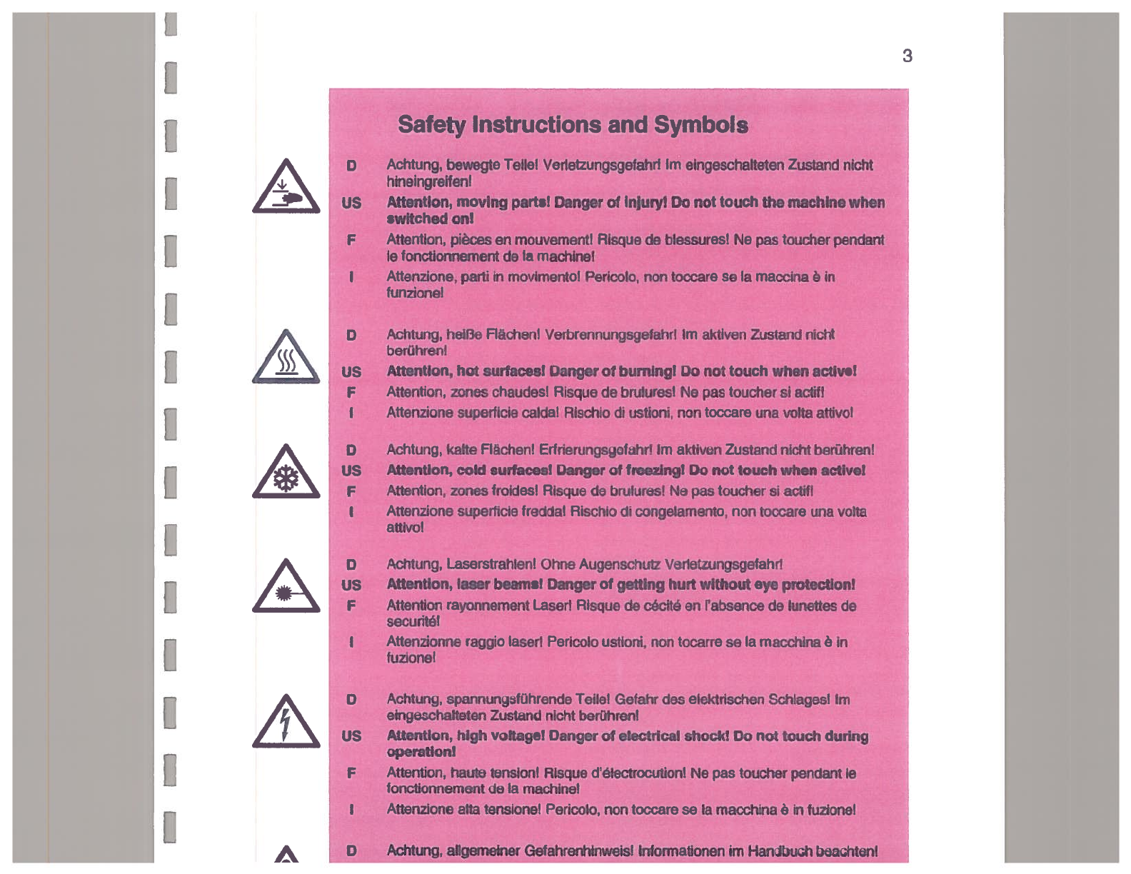
Safety
IMPORTANT:
This section contains informationthat the operator must know
and understandto minimizethe risk of injuries.This information
is consistent with German local and federal safety regulations.
SUSS
equipment is designed to protect the user against all possible hazards. After
review by qualified safety personnel, the user should generate specific safety
procedureswith regardto the particular application ofthe equipmentand localcodes.
Itshould also be made certain that operators are familiar with the procedures. Ifthe
equipment is being usedto probe high voltage devices, the safety proceduresshould
alsobe postedinanobvious locationwhere all operators of theequipmentcannotfail
to readthem.
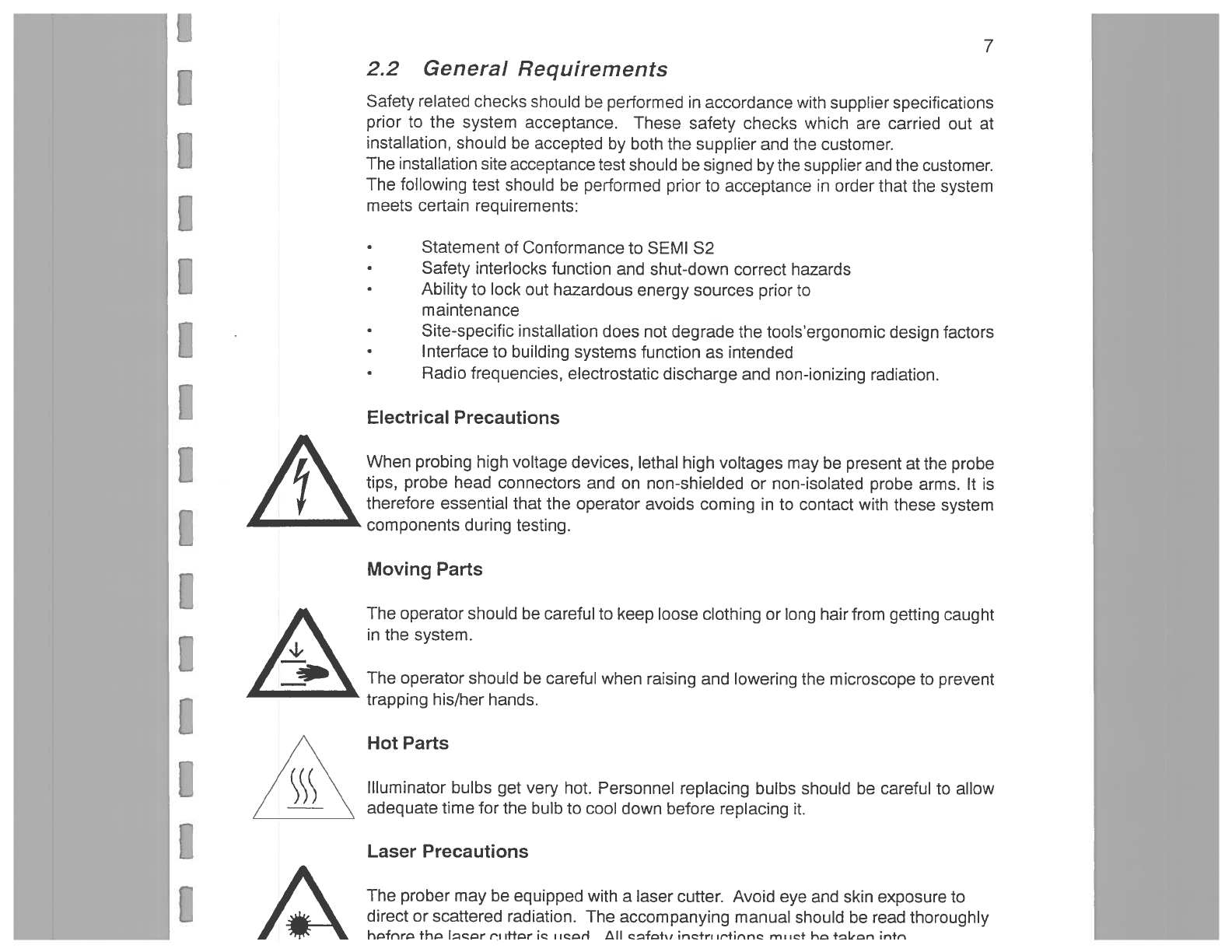
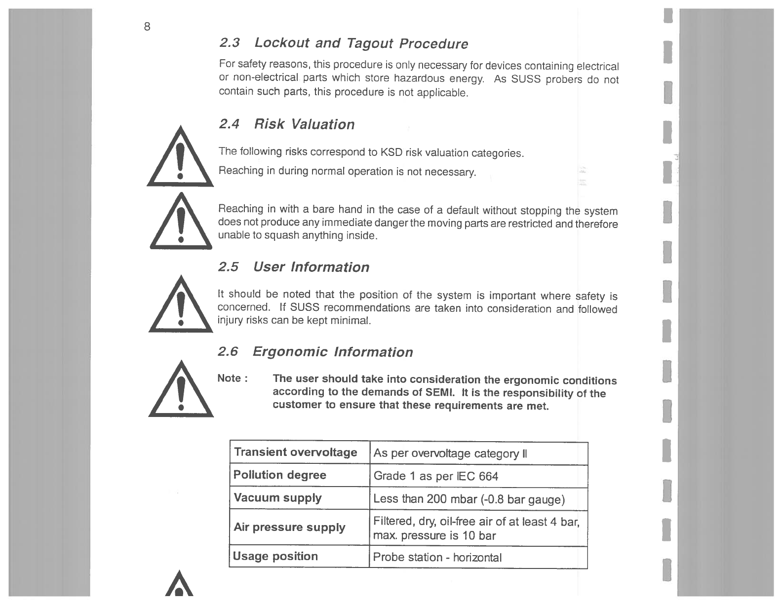
A
2.1
General Safety Precautions
1.
Read and understandthe User manual before usingthe system.
2.
This system must be handled carefully to ensure no harm comesto the user.
During usethere isthe danger of crushing, tripping, burningor beingcaught
up inthe equipment. Thesedangers cannot beavoided dueto the function of
the devices but any possible danger areas are labelledwith the signs onthe
following pagesand will also be highlighted throughout this manual. These
should be studied carefully inorder to avoid any unnecessary risk.
Donotreachintothe proberwhen it is plugged intothe mains. Avoid reaching
intothe chuck area as there is a danger of getting caught. The reararea is
open when workingwith a probe adapter which increasesthis risk.
Never usethe equipment with an open or removed safety cover as
this will increasethe danger of injurythrough moving parts.
A
6.
The device is underlow voltage (upto
28
V
DC). Incaseof equipmentfailure
the lowvoltage can bepresent untilthe operator switchesthecurrentoff atthe
main switch. Do not touch the electrical connections.
7.
Do nottouch the probehead needles with your fingers as this will
dirtythem and may result in injury.
A
Pleasetake noteof the nationaland international safety regulationsfor example
-
,
.