manuals.online logo
Brands
  1. Home
  2. •
  3. Brands
  4. •
  5. Clippard
  6. •
  7. DC Drive
  8. •
  9. Clippard EVPD User manual

Clippard EVPD User manual

WARNING: Installation and operation of electronic and high pressure systems (fluids and
compressed gas) involves risk including property damage and personal injury or death.
Users should be properly trained or certified and take safety precautions.
EVPD PROPORTIONAL VALVE DRIVER
Installation & Operations Manual
Section 1 Wiring
Step 3: Connect Valve to Valve + and Valve -
Terminals (Valve is not polarity sensitive.)
Step 2: Configure Jumper 2 Based on Valve
Step 1: Configure Jumper 1 Based on Command
Step 5: Connect Power to +VDC and GND Terminals. Power requirements are determined by valve
voltage specification. The table below shows the recommended input voltage range for each valve type.
Upon successful powering of the board, the Power
LED (red) will become lit.
Current Max. (Imax)
Current Min. (Imin)
Command
Threshold (DB)
Status Indicator
LED
Power
LED
St
L
E
D
tatu
St
D
Power (See Step 5)
Common (GND)
Valve +
Valve -
Voltage Command
5V
Current Command
0 to 100 mA
0 to 200 mA
0 to 400 mA
10V
Jumper 2 (J2)
EVPD Output
370 mA
185 mA
92 mA
Valve
Jumper 1 (J1)
1.56”
(39.6 mm)
1.31”
(33.3 mm)
1.00” (25.4 mm)
1.26” (32 mm)
0.104”
dia.
DVP/EVP J2 Jumper Board Valve Max.
Valve Type Configuration Output Current*
0 to 5 VDC 400 mA 370 mA
0 to 10 VDC 200 mA 185 mA
0 to 20 VDC** 100 mA** 92 mA
* As per DVP or EVP specifications ** Factory Jumper setting
DVP/EVP J2 Jumper Board Valve Max.
Valve T
y
pe Con
f
iguration Output Current*
0 to 5 VDC 400 mA 370 mA
0 to 10 VDC 200 mA 185 mA
0 to 20 VDC** 100 mA** 92 mA
0 to 5 VDC or
Command 0 to 20 mA or 0 to 10 VDC*
Type 4 to 20 mA
J1
Jumper
Configuration
* Factory Jumper setting. PWM voltage must correspond to
Power LED
DVP/EVP Drive Supply Ideal Supply
Valve Type Voltage Range Voltage
0 to 5 VDC 7 to 12 VDC 12 VDC
0 to 10 VDC 12 to 28 VDC 24 VDC
0 to 20 VDC 24 to 28 VDC 28 VDC
Step 4: Connect Command Source
Unused command input should be grounded to
ensure proper operation of the driver. For PWM command,
use voltage command terminal.
Wiring Configuration
Current Command Type Voltage Command Type
Clippard DVP or
EVP Series Valve
Δ
Jumper selected voltage.
Caution: Do not exceed Command Input Range by more than
25% or permanent damage may occur to the driver.
877-245-6247 | clippard.com
CLIPPARD INSTRUMENT LABORATORY, INC. • ISO 9001:2015
Status Indicator LED
EVPD PROPORTIONAL VALVE DRIVER
Installation & Operations Manual
Section 2 Tuning
Step 1:
Adjusting Command Threshold
This will assure the valve remains closed until the
Command Signal is greater than the Command Threshold
Step 1a: Apply a Command Signal according to the table
below to the driver
Step 1b: Turn DB clockwise until Status Indicator LED (green)
turns Off. Then turn counter-clockwise just enough to turn
the LED On
Step 2: Adjusting Opening Current
This will assure the valve opens at just above the
minimum Command Signal.
Step 2a: Connect supply air to the valve
Step 2b: Apply a Command Signal according to the table
below to the drive (same as Step 1)
Step 2c: Turn Imin
clockwise until valve opens
Command Range 0 to 5 VDC 0 to 10 VDC 4 to 20 mA 0 to 20 mA
Min. Command Signal* 0.1 VDC 0.1 VDC 4.2 mA 0.2 mA
Command Range 0 to 5 VDC 0 to 10 VDC 4 to 20 mA 0 to 20 mA
Min. Command Signal* 0.1 VDC 0.1 VDC 4.2 mA 0.2 mA
Step 3: Adjusting Max Current
This will assure that the maximum Command corresponds to
maximum desired flow
Step 3a: Apply maximum Command Signal according to the
table below to the driver
Step 2d: Turn Imin slightly
counter-clockwise until
valve barely closes
Command Range 0 to 5 VDC 0 to 10 VDC 4 to 20 mA 0 to 20 mA
Signal to Apply 5 VDC 10 VDC 20 mA 20 mA
Step 3b: Turn Imax clockwise to
increase flow to desired maximum. To
reduce maximum flow, turn Imax
counter-clockwise to below the target
flow, then clockwise to the desired
maximum.
Caution: Do not exceed the
maximum current of the DVP/EVP valve
or permanent damage may occur to the valve.
S
ignal to Appl
y
Command Ran
g
e
Status Indicator LED
Turn DB (RP1) clockwise until Status LED is Off
Status Indicator LED (green) will be On at first
Current
Min.
Current
Min.
Current
Max.
1.0
0.9
0.8
0.7
0.6
0.5
0.4
0.3
0.2
0.1
0
0 2 4 6 8 10 12
Command Signal (0 to 10 VDC for this example)
Normalized Driver Output Current
Tuning Parameters
lmax
The output current of the Driver
when the Command Signal is at
maximum value
Command Threshold
When the Command
Signal is less than this
value, the Driver
output current is zero
lmin
The output current of the Driver
when the Command Signal just
exceeds the Command Threshold
WARNING: Installation and operation of electronic and high pressure systems (fluids and
compressed gas) involves risk including property damage and personal injury or death.
Users should be properly trained or certified and take safety precautions.
* The 0.1 VDC value for the Command Threshold is a minimum value that may be increased according to the needs of the application, therefore the Command Signal
values given in steps 1 and 2 are given as minimum values, not as the only possible values.
Turn DB counter-clockwise just enough to turn the Status
Indicator LED (green) On
Status Indicator LED Δ
!
877-245-6247 | clippard.com
CLIPPARD INSTRUMENT LABORATORY, INC. • ISO 9001:2015
877-245-6247 | clippard.com
CLIPPARD INSTRUMENT LABORATORY, INC. • ISO 9001:2015
EVPD PROPORTIONAL VALVE DRIVER
Installation & Operations Manual
Fault Codes
Indicators
The EVPD has two LEDs. A red LED indicates that a power signal
of sucient voltage is properly connected to the board. The
green LED is for status and faults. Its functionality is described
below:
Normal Conditions
Under normal conditions (no faults) the green LED is on when
the command is larger than the command dead band
(command value at which the driver starts supplying current).
3 Blinks
If the voltage command is more than 29.2 volts, the driver will
be operating in the fault mode. The PWM output is forced to
zero and disable. While in high voltage fault, the green LED will
blink 3 times, pause for 1.5 seconds, and then start blinking
again. If the Voltage command drops under 29.2 volts, the driver
will return to working normally.
4 Blinks
If the power supply voltage is less than 6.5 volts, the driver
will also be in the fault mode, the LED will blink 4 times,
pause for 1.5 seconds and then begin blinking again. The
same will occur if the outputs (M+ and M-) are shorted, or
if the driver is overheating. These 3 faults have the same
visualization process (4 blinks).
Once in fault mode, the driver will remain in fault mode
until the condition causing the fault is corrected. The driver
tests for the fault every 5 blinking cycles assuming the
driver has been set-up properly (correct power supply,
wiring and command signal). The only possible“unknown
fault” may be a noise command signal with amplitude in
the range of the Command Dead Band (CDB) setting. Since,
when in normal operation the status LED is programmed
to be ON when the command is bigger than the CDB, and
OFF otherwise, a noisy signal around the CDB may cause
the LED to blink randomly.
A quick way to determine whether the driver is actually
visualizing a fault condition, is to measure the voltage
across the valve (V+ and V-) and change the command to
a value larger than the CDB . If the output voltage remains
zero regardless of the command input, it is a fault, and
should blink 3 or 4 times. If the voltage changes with the
command, the driver is not detecting any fault as
described herein.

Popular DC Drive manuals by other brands

Texas Instruments DRV8811 user guide

Texas Instruments

Texas Instruments DRV8811 user guide

HSB Beta 60-ZSS Original Assembly and Maintenance Manual

HSB

HSB Beta 60-ZSS Original Assembly and Maintenance Manual

Toshiba ATAPI installation manual

Toshiba

Toshiba ATAPI installation manual

SEW-Eurodrive Movigear Performance MGF**-DFC-C Series operating instructions

SEW-Eurodrive

SEW-Eurodrive Movigear Performance MGF**-DFC-C Series operating instructions

Universal Lighting Technologies EVERLINE D700C120UVT-V Series manual

Universal Lighting Technologies

Universal Lighting Technologies EVERLINE D700C120UVT-V Series manual

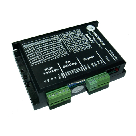
Leadshine Technology DM856 user manual

Leadshine Technology

Leadshine Technology DM856 user manual

Hitachi WJ200-001S instruction manual

Hitachi

Hitachi WJ200-001S instruction manual

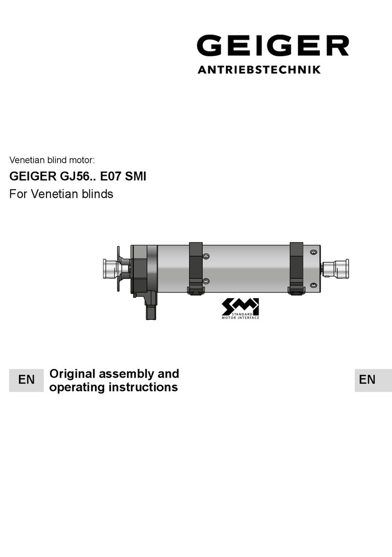
GEIGER GJ56 E07 SMI Series Original assembly and operating instructions

GEIGER

GEIGER GJ56 E07 SMI Series Original assembly and operating instructions

Aumuller FVM2 Assembly and commissioning instructions

Aumuller

Aumuller FVM2 Assembly and commissioning instructions

ABB ACS880-07 user manual

ABB

ABB ACS880-07 user manual

Fröling FBR-G Installation and operating instructions

Fröling

Fröling FBR-G Installation and operating instructions

Lenze E82ZAFVC001 Mounting instructions

Lenze

Lenze E82ZAFVC001 Mounting instructions

Rockwell Automation Allen-Bradley PowerFlex 6000 user manual

Rockwell Automation

Rockwell Automation Allen-Bradley PowerFlex 6000 user manual

Nidec LEROY-SOMER ORTHOBLOC 3000 installation guide

Nidec

Nidec LEROY-SOMER ORTHOBLOC 3000 installation guide

Power Electronics SD 500 Series manual

Power Electronics

Power Electronics SD 500 Series manual

Vacon NXP/P user manual

Vacon

Vacon NXP/P user manual

Danfoss VLT HVAC FC 100 operating instructions

Danfoss

Danfoss VLT HVAC FC 100 operating instructions

Bosch Active Line Original operating instructions

Bosch

Bosch Active Line Original operating instructions

manuals.online logo
manuals.online logoBrands
  • About & Mission
  • Contact us
  • Privacy Policy
  • Terms and Conditions

Copyright 2025 Manuals.Online. All Rights Reserved.