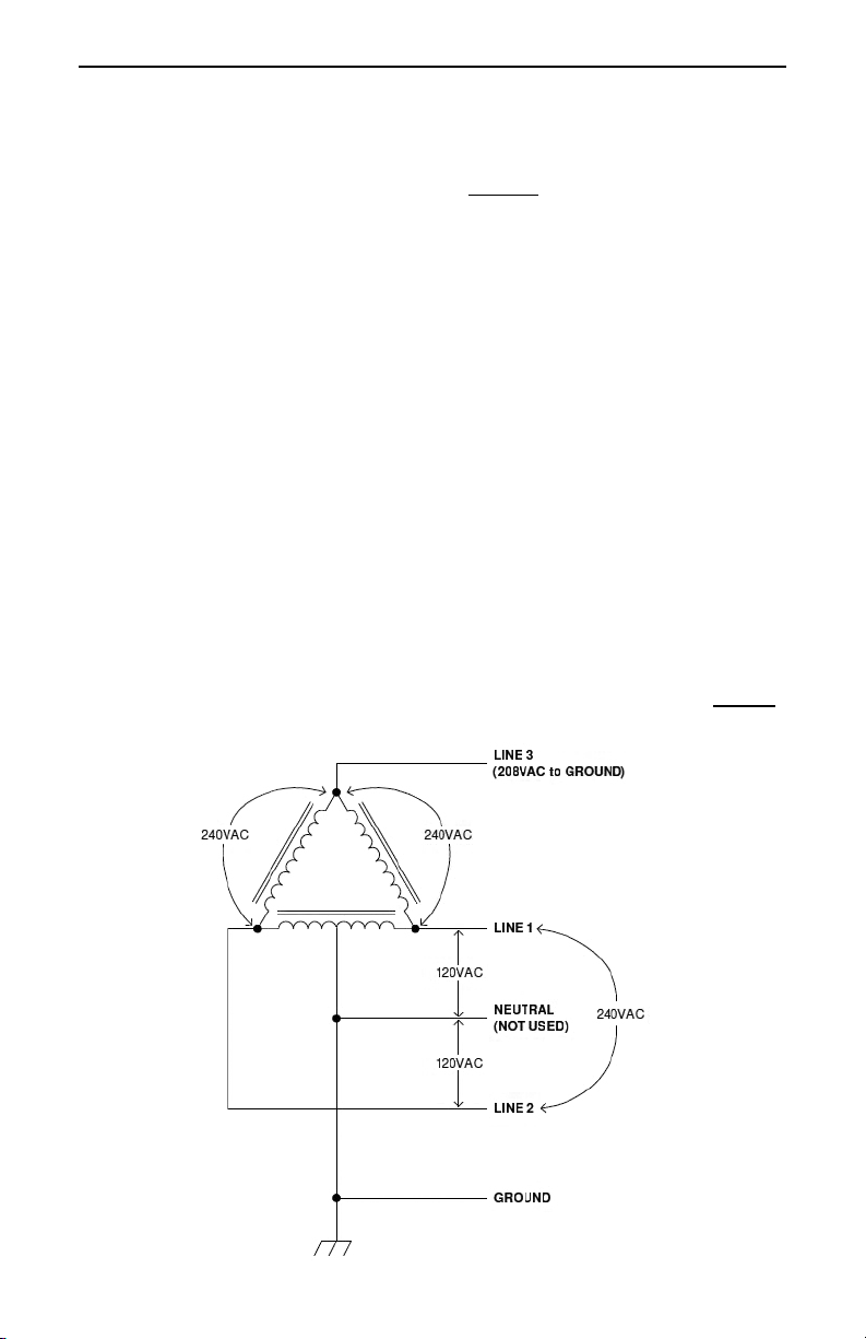
CS 3-Phase Installation Manual
Page 10
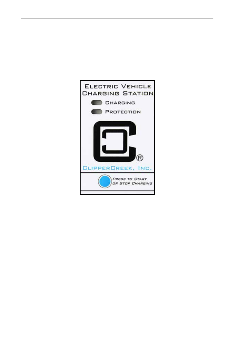
Cold Load Pickup: This feature is built-in to the CS 3-Phase,
but will only be apparent when the utility power fails during
charging. If the charging connector is still plugged into the vehicle
when utility power is restored, the Green CHARGING light will
blink and the unit will not energize the cable for a random time
between 2 and 12 minutes. This is to prevent the utility’s grid from
experiencing a large surge at turn-on, allowing EV’s in the area to
begin drawing current at random times rather than all at once.
The vehicle does not require the operator’s attention after a
power outage. The CS 3-Phase will automatically resume
charging when power is restored.
External Error Indication: Whenever the Red PROTECTION
light turns on, a relay on the board will provide a contact closure
that can be used to remotely indicate that a problem exists. A
eet vehicle yard, for example, could use this feature to light a
lamp or ring a bell in the main oce, indicating that a vehicle
has a charging problem. This early warning helps assure that each
vehicle will be properly charged and ready for use when needed.
Maintenance Current: If the unit is set up for O-Peak
Charging as described above, normal charging current cannot be
drawn by the vehicle until the O-Peak hours. However, the CS
3-Phase can be set up to allow a minimum amount of current while
waiting for the timer to allow full-rate charging. This is known as
Maintenance Current, used for all power needs on the vehicle
except charging the main battery pack. An example would be
preheating the cab, or keeping the auxiliary battery topped o. As
in the O-Peak mode above, the Green CHARGING light will
ash if the vehicle is connected and waiting for the timer to allow
charging. The contactor will close immediately to supply this small
amount of power, but the main battery pack will not be allowed to
charge.
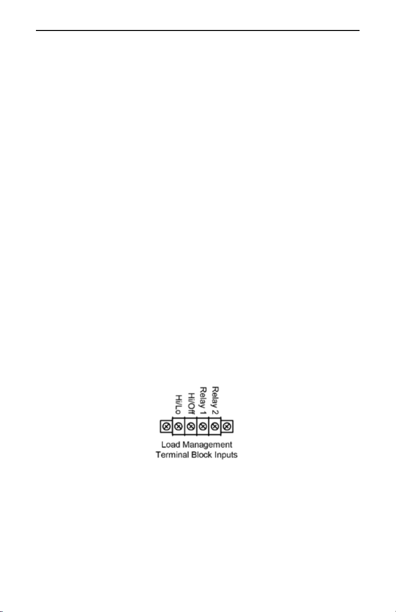
The Maintenance Current feature can be selected by connecting
the Timer’s control wire to the High/Low Pin on the 4-terminal
Terminal Block.
NOTE