ClipperCreek HCS SERIES User manual

Page 1 of 9
HCS SERIES EVSE PEDESTAL
INSTALLATION GUIDE
Please Note
This installation guide includes the latest information at the
time of printing. ClipperCreek, Inc. reserves the right to
make changes to this product without further notice.
Changes or modifications to this product by other than an
authorized service facility may void the product warranty.
Before You Begin:
Read these instructions completely, including the Safety
Instructions. If you have questions about the use of this
product, contact your Service Representative.
Note to the Installer:
Be sure to leave these instructions with the user.
Note to the User:
Keep these instructions for further reference.
ImportantSafetyInstructions
ClipperCreek Electric Vehicle Supply Equipment (EVSE
or “charger”) is designed with the safety concerns of the
end user as an utmost priority; however, the following
safety precautions must be read and followed:
•
The charger and electrical wiring should be installed
by a qualified electrician in accordance with local
electrical codes and ordinances.
•
Grounding Instructions - The charger should be
connected to a grounded, metal, permanent wiring
system; or an equipment-grounding conductor should
be run with circuit conductors and connected to a
grounding terminal or lead on the charger.
Connections to the charger should comply with all
local electrical codes and ordinances.
•
Call your local service provider anytime a procedural
question arises; DO NOT attempt to perform a
procedure you are unsure of.
•
Read all installation instructions carefully before
performing the pedestal and charger installation.
Notes:_________________________
_____________________________
_____________________________
_____________________________
_____________________________
_____________________________
_____________________________
_____________________________
_____________________________
_____________________________
InstallationRequirements
Required Equipment for a Single-Mount Pedestal with
one HCS Charging Station (One EVSE per Pedestal):
•
One (1) ClipperCreek HCS EVSE Pedestal Kit.
•
One (1) ClipperCreek HCS Charging Station (EVSE).
•
One (1) dedicated 208 or 240 VAC branch circuit.
•
One (1) circuit breaker appropriately sized for the
EVSE charging capacity. 1
•
Two (2) Live Line conductors with enough length to
comfortably pull all the way through and above the top
of the pedestal.2
•
One (1) Ground Line conductor with enough length to
comfortably pull all the way through and above the top
of the pedestal.2
•
Conduit sized to fit all three conductors.
•
Four (4) Anchor Bolts with Nuts and Washers
Required Equipment for a Dual-Mount Pedestal with
two HCS Charging Stations (Two EVSEs per Pedestal):
•
One (1) ClipperCreek HCS EVSE Pedestal Kit.
•
One (1) ClipperCreek Dual-Mount HCS Pedestal Kit.
•
Two (2) ClipperCreek HCS Charging Stations (EVSEs).
•
Two (2) dedicated 208 or 240 VAC branch circuits.
•
Two (2) circuit breakers, appropriately sized with
respect to the charging capacity of each EVSE. 1
•
Two pairs (2x2) Live Line conductors (one pair for each
EVSE) with enough length to comfortably pull all the
way through and above the top of the pedestal. 2
•
Two (2) Ground Line conductors (One for each
EVSE) or a single bonded Ground Line with
enough length to comfortably pull all the way
through and above the top of the pedestal.2
•
Conduit sized to fit all Live Line and Ground Line
conductors.
•
Four (4) Anchor Bolts with Nuts and Washers
1 Refer to the EVSE documentation to determine the
appropriate circuit breaker current capacity.
2 All conductors must be appropriately sized for the
EVSE current capacity, in accordance with local and
NEC electrical codes.
ToolsRequiredforAssemblingthePedestal
The following tools are required for the installation and
assembly of the pedestal components.
•
L-shape T27 Torx Driver (there are some tight spaces,
advise using both the long and short T27’s for faster
assembly)
•
#2 Phillips Head Screwdriver
•
5/16” Flathead Screwdriver (for Ground Block Lug)
•
Box Wrench (appropriately sized for the Anchor Nuts)

Page 2 of 9
HCS Series
EVSE Pedestal Installation
Guide
PedestalDimensions
Figure 1: HCS Pedestal Dimensions for Single-Mount and Dual-Mount Installations
Figure 2: HCS Pedestal Base Dimensions Figure 3: An Installation Cross-Section

Page 3 of 9
HCS Series
EVSE Pedestal Installation
Guide
PackingLists
0300-00-
024
HCS Pedestal Kit, Standard 4 Foot, Single-Mount
Part Number
QTY Description
1003-0014 1Pedestal Metalwork, Cap with Rear Flange
NOTE: this item may already be attached to the top of the pedestal.
1003-0023 2Pedestal Metalwork, Base Cover
1003-0032 1Pedestal Metalwork, 4-Foot Post
1003-0037 1Pedestal Metalwork, Hole Cover Plate
1003-0039 1Pedestal Metalwork, HCS Charger Mounting Plate
4000-0005 2 Machine Screw, Pan Head, 8-32, ½” Length, Phillips
4000-0010 4Machine Screw, Tapered Flat Head, 6-32 Size, 3/8" Length, Phillips
4000-0011 3Machine Screw, Tapered Flat Head, 1/4-20 Size, 3/4" Length, T27 Torx
4000-0012 2Machine Screw, Button Head, 1/4-20 Size, 1" Length, T27 Torx
4000-0019 2 Machine Screw, Button Head, 1/4-20 Size, 2" Length, T27 Torx
4002-0001 2 Washer, #8, Zinc, 3/16”ID, 7/16” OD
4002-0002 4Washer, Galvanized Steel, Neoprene Bonded Seal, 1/4" ID, 5/8" OD
4002-0004 1 Washer, Liquid Tight Sealing, Thermoplastic, ½”
4013-0009 1 Pedestal Conduit Assembly, Standard 90 degree 1/2” NPT Fitting
4015-0000 4Plug, Plastic Push-In, 1-3/32" ID, 1-7/32" OD
4015-0001 2Plug, Plastic Push-In, 1-3/8" ID, 1-1/2" OD
4015-0004 2 Plug, Plastic Push-In, 7/8" ID, 1-1/64" OD
OptionalOrderableItems
0300-00-020 HCS Dual-Mount Kit for Standard 4 Foot Pedestal (Optional)
Part Number QTY Description
1003-0015 1Pedestal Metalwork, Cap without Rear Flange
1003-0039 1Pedestal Metalwork, HCS Charger Mounting Plate
4000-0005 2 Machine Screw, Pan Head, 8-32, ½” Length, Phillips
4000-0011 1Machine Screw, Tapered Flat Head, 1/4-20 Size, 3/4" Length, T27 Torx
4000-0012 2Machine Screw, Button Head, 1/4-20 Size, 1" Length, T27 Torx
4000-0019 2 Machine Screw, Button Head, 1/4-20 Size, 2" Length, T27 Torx
4002-0001 2 Washer, #8, Zinc, 3/16”ID, 7/16” OD
4002-0002 4Washer, Galvanized Steel, Neoprene Bonded Seal, 1/4" ID, 5/8" OD
4002-0004 1 Washer, Liquid Tight Sealing, Thermoplastic, ½”
4013-0009 1 Pedestal Conduit Assembly, Standard 90 degree 1/2” NPT Fitting
0300-06-000 120V Ground Fault Receptacle Kit*
Part Number QTY Description
4015-0002 1Plug, Knockout Bushing, 1.109" OD, 3/4" Trade Size Aperture
4301-0000 1GFCI Ground Fault Receptacle, 15A, 125V, NEMA 5-15R, Single Socket
with Switch
4301-0001 1Gang Box, Single, Silver Metal
4301-0002 1Weatherproof Receptacle Cover, Clear, Single Gang, 2-3/4" Depth
* The Ground Fault Receptacle Kit includes a 120VAC GFCI receptacle and housing. It may be installed at the
knock-outs located 24 inches above the base on either side of the pedestal.

Page 4 of 9
HCS Series
EVSE Pedestal Installation
Guide
1. Concrete Pad Requirements
The location, dimensions, and composition of the concrete
pad underlying the pedestal should always adhere to local
building codes. The following dimensions are minimum
recommended values. Always verify that installation plans
adhere to local code requirements prior to proceeding.
•
The pad area must be a minimum of 18” to a side.
•
The concrete must be poured a minimum depth of 18”.
•
If there is no bumper block, the center of the pedestal
base should be situated 36” behind the curb.
•
If a bumper block is in place, the center of the pedestal
base should be situated 12” behind the curb.
Figure 4: Proper Distance to the Curb
2. Anchor Bolt Placement
A minimum of four (4) anchor bolts must be embedded in
the concrete pad for the purposes of securing the pedestal
post. The pedestal base is designed to permit the anchor
bolts to be arranged in many configurations, including
the following:
For the Standard 10” Square Pattern:
•
Arrange four (4) 1/2” or 3/8” anchor bolts in a 10”
square pattern. This placement corresponds to the
corner cutouts in the pedestal base.
For the Alternate 5.25” x 11.1” Rectangular Pattern:
•
Arrange four (4) 3/8” anchor bolts in a 5.25” by 11.1”
rectangular pattern. This placement corresponds to the
short inner cutouts in the pedestal base.
For the Alternate 10” x 4.75” Rectangular Pattern:
•
Arrange four (4) 1/2” anchor bolts in a 10” by 4.75”
rectangular pattern. This placement corresponds to fall
within the long inner cutouts in the pedestal base.
Maximum Anchor Bolt Height:
•
The anchor bolts should not protrude more than 3”
above the surface of the concrete pad.
Use the Pedestal Base Pattern Template:
To better facilitate the installation of the anchor bolts, a
cardboard template in the shape of the pedestal base is
included in the pedestal kit. This template is provided as a
knock-out piece on the back of the cardboard box in which
the cover plate is packaged. The template is specific for
two bolt patterns: the standard 10” x 10” pattern and an
alternate 5.25” x 11.1” rectangular pattern.
Figure 5: Bolt Pattern Template Knockout
3. Mounting the Pedestal Post
Once the concrete pad with anchor bolts has been prepared
and the three service conductors have been pulled through
the underground conduit, the pedestal post may be placed.
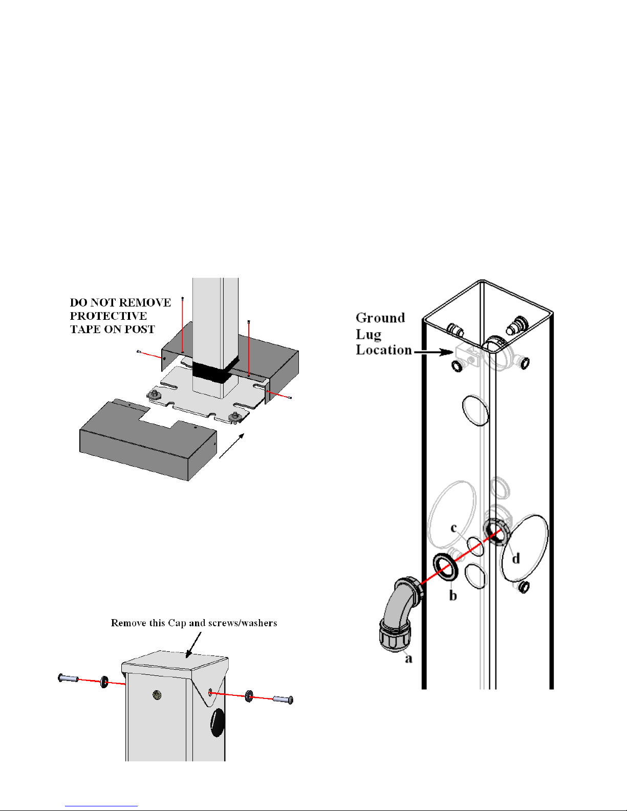
Note: DO NOT remove the tape at the bottom of the
pedestal. This tape is provided for finish and weather
protection of the pedestal post.
•
Feed the three service conductors up through the
inside of the pedestal post. The conductors must be of
sufficient length to pass beyond the top of the pedestal
so that final connections can be worked with
comfortably at a later step.
•
Align the pedestal post base notches with the four
anchor bolts and ease it into place.
•
Nuts and washers may be used under the pedestal base
to adjust the vertical alignment of the pedestal should
the concrete pad not be level.
•
Secure the pedestal post base to the concrete anchor
bolts using appropriately sized nuts and washers.
•
The anchor bolts, nuts and washers used for the
installation of the pedestal base are not included in the
pedestal kit and must be purchased separately.

Page 5 of 9
HCS Series
EVSE Pedestal Installation
Guide
Figure 6: Pedestal Post Mounting by Pattern
Page 6 of 9
HCS Series
EVSE Pedestal Installation
Guide
4. Install the Pedestal Base Cover
A two-piece pedestal base cover set is included in the
pedestal kit. The purpose of the pedestal base cover is to
beautify the installation and to protect against injury from
protruding anchor bolts.
•
The two covers are of an identical overlapping design.
•
Slide one cover on the front side of the pedestal base
until the center notch surrounds half of the pedestal
post. Slide the other cover onto the rear side in the
same manner. Ensure that the flanges of each cover
piece are tucked inside of the opposite cover.
•
Align the four screw holes of each cover piece with
the corresponding screw holes on the opposite cover.
•
Secure each cover piece to the other with four (4) #6-
32 x 3/8" flat-head tapered screws using a #2
Philips- head screwdriver.
Figure 7: The Pedestal Base Covers
5. Remove the Pedestal Post Cap
A pedestal cap is provided to cover the opening to protect
the conductors and inner pedestal from the elements. It
may have already been assembled on the post for
protection during shipping. Temporarily remove this cap
for additional access to electrical connections.
Figure 8: Cap Removal
6. Install the Conduit Assembly
•
Knock-out the 1½” plastic plug located 10” down from
the top of the pedestal on the left side.
•
Connect the following to the Pedestal Post in the order
as shown in Figure 9:
a) The Standard 90 degree 1/2” NPT Fitting
b) The ½” liquid tight sealing washer
c) The open pedestal hole
d) The first locknut from the NPT Fitting (inside of the
pedestal)
•
Tighten so that the bottom opening of the NPT Fitting
is facing downward.
•
For Dual-Mount Installations, repeat on the opposite
side.
Figure 9: HCS Pedestal Conduit Assembly

Page 7 of 9
HCS Series
EVSE Pedestal Installation
Guide
7. Install the Charger Mounting Plate
A charger mounting plate is affixed to the front of
the pedestal post to provide a flat and rigid base on
which the charger can be mounted. In the case of a
Dual-Mount installation, a second mounting plate is
affixed to the opposite side of the pedestal post.
•
Hold the charger mounting plate against the front
side of the pedestal post as shown in Figure 11.
•
Align the center screw hole of the mounting plate
with the corresponding top threaded insert on the
front of the pedestal post.
•
Secure the mounting plate to the pedestal with one
(1) 1/4-20 x 3/4" Torx flat-head tapered screw
using a T27 Torx driver. Tighten until the head of
the screw is flush with the surface of the mounting
plate.
For Dual-Mount Charger Installations:
•
The Dual-Mount Kit includes a second charger
mounting plate. This second mounting plate is
affixed to the back side of the pedestal post,
opposite of the first mounting plate.
•
As with the first mounting plate, align the center
screw hole of the mounting plate with the
corresponding top threaded insert on the front of the
pedestal post and tighten one (1) 1/4-20 x 3/4" Torx
flat-head tapered screw using a T27 Torx driver
until the screw head is flush with the surface of the
mounting plate.
Figure 11: The Charger Mounting Plate
8. Mounting a Single Charger to the Pedestal
With the mounting plate in place, the pedestal is now
ready for a single charger to be mounted.
•
Place a 1/4" Neoprene-bonded sealing washer around the
shaft of each of the two (2) 1/4-20 x 2" Torx button-
head screws. The metal portion of the washer should
face the head of the screw while the neoprene should
face the tip of the screw.
•
There are two different styles of HCS plastic angle
washers. The correct style to use with the HCS Pedestal
is the Perpendicular Screw Mount. These washers are
included with the HCS Charging Station and do not
accompany this kit. Refer to Figure 12.
Figure 12: HCS Plastic Angle Washers
•
Align the two screw holes on the top and bottom of the
charger with the corresponding threaded inserts on the
mounting plate.
•
Use a T27 Torx driver to secure the top of the charger
first using one (1) 1/4-20 x 2" Torx button-head screws
with neoprene washer and HCS Plastic Angle Washer
as shown in Figure 13. Do not over-tighten.
Figure 13: Mounting a Single HCS Charger:
Install Top screw FIRST

Page 8 of 9
HCS Series
EVSE Pedestal Installation
Guide
•
Secure the bottom of the charger using one (1) 1/4-20 x
2" Torx button-head screws with neoprene washer and
HCS Plastic Angle Washer as shown in Figure 14.
•
For an installation with two chargers affixed to the
same post, repeat the previous steps for the opposite
side.
Figure 14: Mounting a Single HCS Charger:
Install bottom screw LAST
9. Connect the Wiring
The HCS has a flexible conduit extension with three
conductors. These conductors must be routed through the
side of the pedestal and the ninety-degree ½” NPT for
connection.
•
Trim the EVSE conduit to length. The recommended
length to remain is 12 inches as measured from the
bottom of the EVSE.
•
Route the three conductors that come through the
EVSE’s flexible conduit through the NPT connection
and into the Pedestal Post.
•
No disassembly of the NPT Fitting is required. Push
the conduit onto the NPT Fitting ferrule and then
tighten the domed sealing nut on the NPT fitting.
•
For Dual-Mount Installations, repeat on the opposite
side.
•
All conductor and ground lug connections inside the
Pedestal Post must be completed at this time. The top
access hole will be blocked after this step.
10. Re-Install the Pedestal Post Cap
The pedestal cap is provided to cover the opening to
protect the conductors and inner pedestal from the
elements. Install the appropriate pedestal cap for a
single-mount or dual-mount charger installation as
described below.
For Single-Mount Charger Installations:
•
Single-mount charger installations utilize the standard
post cap provided in the pedestal kit. This post cap
includes a flange on one side. Place the post cap onto
the top of the pedestal, with the flange facing the rear.
•
Align the screw holes on each side of the post cap
with the corresponding threaded inserts on the sides
of the pedestal.
•
Place a 1/4" Neoprene-bonded sealing washer around
the shaft of two (2) 1/4-20 x 1" Torx button-head
screws. The metal portion of the washer should face
the head of the screw while the neoprene should face
the tip of the screw.
•
Secure the cap to the pedestal with the two (2) 1/4-20
x 1" Torx button-head screws (with washers) using a
T27 Torx driver.
For Dual-Mount Charger Installations:
•
Dual-Mount charger installations utilize a replacement
post cap provided in the Dual-Mount Kit. This post
cap lacks a flange at the rear. Place the post cap onto
the top of the pedestal.
•
Align the screw hole on each side of the post cap with
the corresponding thread insert on the side of the
pedestal.
•
Place a 1/4" Neoprene-bonded sealing washer around
the shaft of two (2) 1/4-20 x 1" Torx button-head
screws. The metal portion of the washer should face
the head of the screw while the neoprene should face
the tip of the screw.
•
Secure the cap to the pedestal with the two (2) 1/4-20
x 1" Torx button-head screws (with washers) using a
T27 Torx driver.
Figure 15: The Pedestal Post Cap
11. Install the Cover Plate
The cover plate is provided to cover the electrical access hole
for Single-Mount Pedestals only. Skip this step if you are
installing a Dual-Mount.
•
Secure the cover plate to the Single-Mount Pedestal
using two (2) 1/4-20 x 3/4" Torx flat-head tapered
screws using a T27 Torx driver until the screw head
is flush with the surface of the mounting plate.
Page 9 of 9
HCS Series
EVSE Pedestal Installation
Guide
Figure 16: Installing the Cover Plate
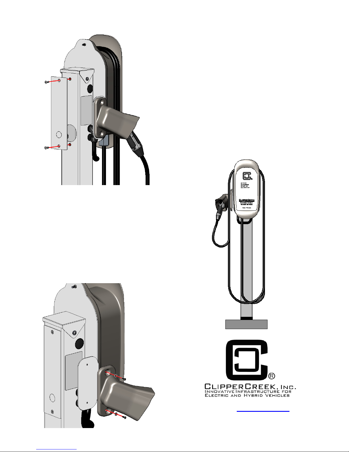
12. Install the Holster
The holster, which is included with the station, is to
stow the vehicle connector. To install, follow the steps
below.
•
Place a #8 washer around the shaft of each of the two
(2) 8-32 pan head screws.
•
Secure the Holster to the Mounting Plate as shown.
•
For an installation with two chargers affixed to the
same post, repeat the previous steps for the opposite
side.
Figure 17: Mounting the Holster
13. Mounting Two Chargers to the Pedestal
For an installation with two chargers affixed to the same
post, repeat the previous steps 7 through 11 for the opposite
side.
14. Wrap and Stow the Vehicle Connector
•
Loosely wrap the cable around the HCS as shown in
Figure 18.
•
Stow the Vehicle Connector in the holster. The button
does not need to be pressed, simply insert until you
hear the click to lock in place.
•
Verify the safety of the installation prior to turning on
the circuit breaker.
•
Refer to the Charging Station User’s Guide for further
operational and maintenance information.
Figure 18: Wrap and Stow the Connector
Visit us at www.clippercreek.net
HCS Series EVSE Pedestal Installation Guide
Version 4, April 2016
Other manuals for HCS SERIES
2
Table of contents
Other ClipperCreek Batteries Charger manuals

ClipperCreek
ClipperCreek HCS User manual

ClipperCreek
ClipperCreek CS-100 User manual

ClipperCreek
ClipperCreek ProMountDuo PMD-10R User manual

ClipperCreek
ClipperCreek CS 3-Phase User manual

ClipperCreek
ClipperCreek ProMountDuo PMD-10T User manual

ClipperCreek
ClipperCreek CS-40 User manual

ClipperCreek
ClipperCreek LCS Series User manual

ClipperCreek
ClipperCreek LCS Series User manual

ClipperCreek
ClipperCreek HCS SERIES User manual

ClipperCreek
ClipperCreek EV Series User manual


