ClipperCreek HCS SERIES User manual

ClipperCreek, Inc.
Innovative Infrastructure for
Electric and Hybrid Vehicles
• • • • • • •
Model HCS
HCS Optional Features User Manual
KEEP THIS MANUAL
Use in conjunction with the HCS User Manual.
HCS Optional Features User Manual
2
To view the latest version of this manual please visit
clippercreek.com/installation-manuals
HCS Optional Features User Manual, Version 1, June 2020
Copyright © 2020 ClipperCreek, Inc.
All rights reserved. Printed in the USA.
Manual Number: 7004-0036
PLEASE NOTE
This user manual includes the latest information at the time of
printing. ClipperCreek, Inc. reserves the right to make changes to
this product without further notice. Changes or modications to this
product by other than an authorized service facility may void the
product warranty.
Contact a Customer Service Representative with any questions about
the use of this product. (877) 694-4194
WARNING: This product can expose you
to chemicals, including Carbon Black, which
is known to the State of California to cause
cancer. For more information go to:
www.P65Warnings.ca.gov
ADVERTENCIA: Este producto puede
exponerte a químicos, incluso Negro
Carbón, que se conocido por el Estado de
California como causante de cáncer. Para
más información visite:
www.P65Warnings.ca.gov
AVERTISSEMENT: Ce produit peut vous
exposer à des agents chimiques, y compris
Noir Carbone, identiés par l’État de
Californie comme pouvant causer le cancer.
Pour de plus amples informations, prière de
consulter: www.P65Warnings.ca.gov

HCS Optional Features User Manual
3
CONTENTS
FCC INFORMATION.................................................................................5
INSTALLATION .........................................................................................6
OPTIONAL FEATURES ............................................................................7
Overview 7
ChargeGuard Enabled HCS 9
Replacement Keys 11
ChargeGuard EX Enabled HCS 12
Share2 Enabled HCS 14
Share2 Wiring Instructions: 15 Wire Harness 14
Verify Share2 Function is Working Properly 15
Share2 Wiring Instructions: 8 and 10 Wire Harness 16
Verify Share2 Function is Working Properly 16
Share2 Operating Instructions 17
COSMOS Load Management Enabled HCS 19
COSMOS Wiring Instructions: 15 Wire Harness 20
COSMOS Wiring Instructions: 8 or 10 Wire Harness 22
COSMOS Digital Interface Connection 24
COSMOS Digital Interface Compatibility 24
COSMOS Open Collector Outputs: 15 Wire 26
COSMOS Open Collector Output: 8 or 10 Wire 28
COSMOS ChargeGuard EX Enabled HCS 29
COSMOS ChargeGuard EX: 15 Wire Instructions 29
COSMOS ChargeGuard EX Activation Instructions: 15 Wire 30
COSMOS ChargeGuard EX: 10 Wire Instructions 31
COSMOS ChargeGuard EX Activation Instructions: 10 Wire 32
CUSTOMER SUPPORT...........................................................................33

HCS Optional Features User Manual
4
ILLUSTRATIONS
Figures
1. ChargeGuard ON or Enabled Position: Charging is enabled ..........................9
2. ChargeGuard OFF or Restricted Access Position: The EVSE will
be enabled for as long as the vehicle remains plugged in. The EVSE
will reset when the vehicle connector is unplugged. ....................................10
3. ChargeGuard EX with Orange and Yellow Wires .........................................13
4. ChargeGuard EX Wire Detail........................................................................13
5. Share2: 15 Wire Harness................................................................................15
6. Share2: 8 or 10 Wire Harness ........................................................................16
7. Share2 Connect Vehicle #1............................................................................17
8. Share2 Connect Vehicle #2............................................................................18
9. Share2 One of the Vehicles Disconnects or Completes Charging.................18
10. COSMOS Serial and Digital Interface: 15 Wire ........................................... 21
11. COSMOS Serial and Digital Interface: 8 or 10 Wire....................................23
12. COSMOS Power Level Wiring: 15 Wire ......................................................25
13. COSMOS Power Level Wiring: 8 or 10 Wire...............................................27
14. COSMOS ChargeGuard EX Controls: 15 Wire............................................30
15. Enable COSMOS ChargeGuard EX: 15 Wire............................................... 30
16. COSMOS ChargeGuard EX Controls: 10 Wire............................................31
17. Enable COSMOS ChargeGuard EX: 10 Wire............................................... 31
Tables
1. HCS Series Optional Features.........................................................................7
2. COSMOS Wiring Instructions: 15 Wire Harness..........................................20
3. COSMOS Wiring Instructions: 8 or 10 Wire Harnesses ...............................22
4. COSMOS Digital Interface Compatibility....................................................24
5. COSMOS Load Management Digital Inputs: 15 Wire .................................25
6. COSMOS Open Collector Outputs: 15 Wire ................................................26
7. COSMOS Load Management Digital Inputs: 8 or 10 Wire ..........................27
8. COSMOS Open Collector Output: 8 or 10 Wire...........................................28
9. COSMOS ChargeGuard EX Wiring: 15 Wire...............................................30
10. COSMOS ChargeGuard EX Wiring: 10 Wire...............................................31

HCS Optional Features User Manual
5
FCC INFORMATION
This device complies with Part 15 of the FCC rules. Operation
is subject to the following two conditions: (1) This device may
not cause harmful interference, and (2) This device must accept
any interference received, including interference that may cause
undesired operation.
This product has been designed to protect against Radio Frequency
Interference (RFI). However, there are some instances where high
powered radio signals or nearby RF-producing equipment (such as
digital phones, RF communications equipment, etc.) could affect
operation.
If interference to the EVSE is suspected, the following steps should
be taken before consulting a ClipperCreek®Sales or Service
Representative for assistance:
1. Reorient or relocate nearby electrical appliances or
equipment during charging.
2. Turn off nearby electrical appliances or equipment
during charging.
CAUTION: Changes or modications to this product
by other than an authorized service facility may void
FCC compliance.
ATTENTION: Modications apportées à ce produit par
qui conque autre qu’un centre de service autorisé peut
annuler la conformité FCC.
ATENCIÓN: Cambios o modicaciones a este product por
otros que no sean un centro de servicio autorizado pueden
anular el cumplimiento con la FCC.

HCS Optional Features User Manual
6
INSTALLATION
Install the HCS EVSE in accordance with the instructions
provided in the HCS User Manual. This manual provides
information on conguring and operating optional features
such as ChargeGuard, Share2, and COSMOS included with
some HCS models.
A digital copy of the standard HCS User Manual can be found
at: clippercreek.com/installation-manuals

HCS Optional Features User Manual
7
OPTIONAL FEATURES
Overview
The HCS Series EVSE can be built with additional functionality
including abilities for access control, shared circuit power, and
load management.
These features can often be used together, but must be built
to order. Reference the chart below to verify which combination
of HCS expanded functionalities would best suit specic
requirements.
Contact a Customer Service Representative at (877) 694-4194 for
additional information. Installation instructions for each expanded
functionality follow.
Table 1: HCS Series Optional Features
*Not simultaneous with Load Management or Serial
HCS SERIES
Optional Features
ChargeGuard X0
ChargeGuard EX X 2
Share2 X X X 8 or 15
COSMOS/Share2 X X X X 8 or 15
COSMOS/Share2 X X X X 10 or 15
with ChargeGuard
with ChargeGuard EX
Built-In
Key
External
Key
SerialLoad
Management
*Shared
Circuit
Power
# of
Control
Wires

HCS Optional Features User Manual
8
NOTE: Each HCS delivered with Optional Features
that use Control Wires (see Table 3) comes with 3 feet
(1 m) of conduit containing the communication wires.
When using Share2, HCS stations can be placed up 100
feet (30.5 m) apart. ClipperCreek utilizes 24 AWG
(American Wire Gauge) Belden cable for the
communication harness. Other 24 AWG cabling is
acceptable. The 8 Wire Harness uses Belden cable #9538;
the 10 Wire Harness uses Belden cable #9540; and the 15
Wire Harness uses Belden cable #9541.

HCS Optional Features User Manual
9
Figure 1: ChargeGuard
ON or Enabled Position: Charging is
enabled
ChargeGuard
Enabled HCS
ChargeGuard is a built-in key based access control option. Refer to
these instructions to operate a ChargeGuard enabled HCS EVSE.
1. Connect the HCS EVSE to the vehicle with the
SAE J1772 connector.
2. To enable charging:
a) Insert the key into the switch located on the right side
of the HCS EVSE.
b) Turn the key 90° clockwise to the vertical position as
shown in the Figure 1.
c) The “CHARGING” LED light will illuminate green on
the front panel, indicating the vehicle is now being
charged.
3. To allow charging of Multiple Vehicles:
a) Leave the key in the present vertical position.
This allows disconnection of the EVSE from one
vehicle and reconnection to the same or another vehicle
without moving the key.
b) The EVSE will be enabled and power will be available
to vehicles as long as the key remains in the vertical
position.

HCS Optional Features User Manual
10
NOTE: The key cannot be removed in the vertical
position. See Step 4 for key removal instructions.
4. To restrict access:
a) Turn the key counterclockwise 90° as shown in
Figure 2.
b) Remove the key.
c) If a vehicle is connected and charging, that vehicle will
continue to charge as long it remains connected to the
EVSE.
d) Once the vehicle is disconnected from the EVSE, the
EVSE will require the key to activate another charging
session.
Figure 2: ChargeGuard OFF or Restricted Access Position:
The EVSE will be enabled for as long as the vehicle remains
plugged in. The EVSE will reset when the vehicle connector is
unplugged.

HCS Optional Features User Manual
11
Replacement Keys
Should replacement keys be required, contact the ClipperCreek
ofce at (877) 694-4194. Please have the EVSE serial number
available for reference.
NOTE: If the Share2 option is desired to work in
conjunction with the ChargeGuard option, these two
options must be ordered and built at the same time
(Share2 and ChargeGuard are factory-installed options
and cannot be installed in the eld). The optional Share2
feature allows two EVSE to share power supplied by one
circuit breaker. Please refer to the Share2 Enabled HCS
section of this User Manual for further instructions.

HCS Optional Features User Manual
12
ChargeGuard EX Enabled HCS
ChargeGuard EX provides a simple interface to connect the
ClipperCreek HCS EVSE to an existing building access control
or other third party access control system. With ChargeGuard EX
a momentary contact closure driven by successful authentication
in an access control system can activate the HCS ChargeGuard
EX enabled station for a single charging session. Alternatively,
maintaining the contact closure will leave the station enabled for
multiple charging sessions until the connection is released.
When the Orange and Yellow control wires are shorted together,
the EVSE is “ON” and ready to charge a vehicle. When the
wires are disconnected, the station is “OFF” and requires a valid
activation through the access control system in order to begin
charging again. Refer to Figure 3 and Figure 4.
ChargeGuard EX can be utilized in two ways:
1. If individual access control is desired (for each charge
session), the access control system will need to provide
a momentary short to the Orange and Yellow wires
which will activate the station for a single charge
session. In this implementation once the vehicle is
disconnected the station will require a successful
authorization through the access control system.
2. If open access is desired, connect the Orange and
Yellow wires for as long as open access is desired.
As long as the Orange and Yellow wires are shorted
together, the station will be enabled for use.
HCS Optional Features User Manual
13
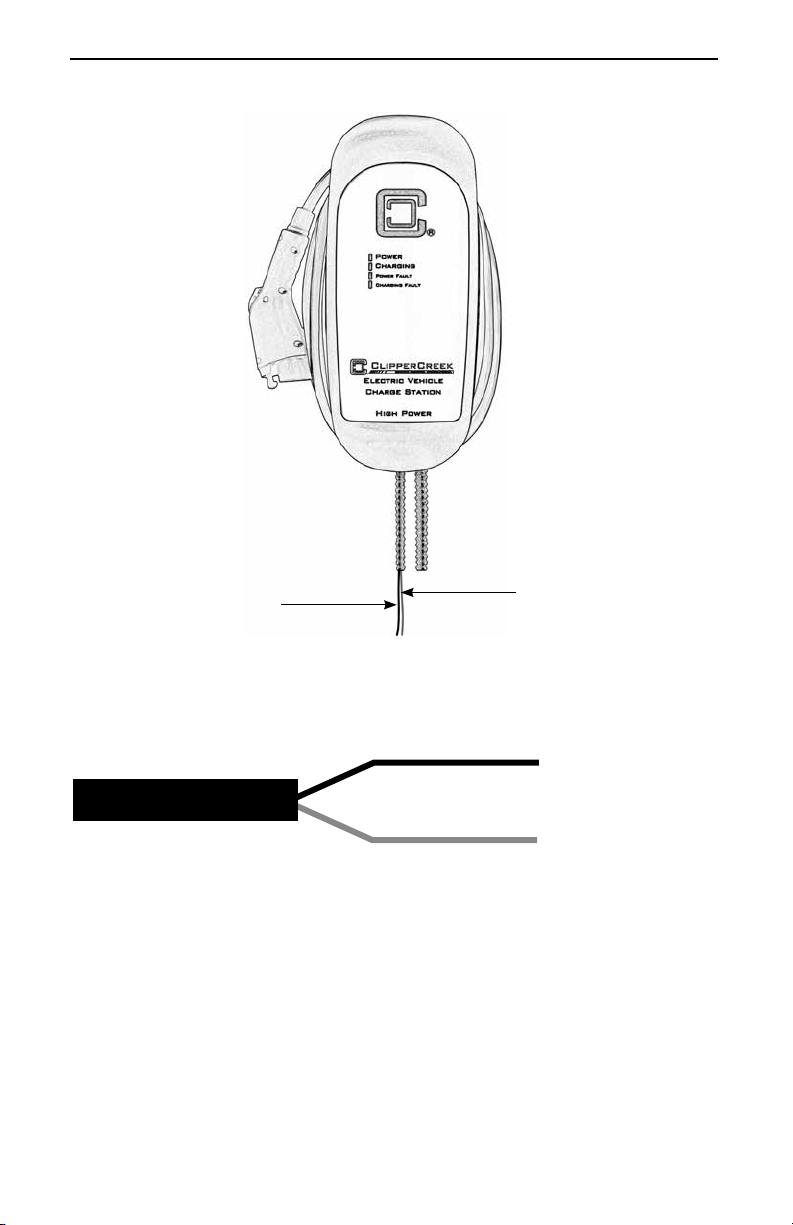
Figure 4: ChargeGuard EX Wire Detail
Please refer to these instructions to operate the ChargeGuard EX
enabled HCS EVSE:
1. Connect the HCS EVSE to the vehicle with the SAE
J1772 connector.
2. Enable charging by using access control.
3. The “CHARGING” LED light will illuminate green on
the front panel, indicating the vehicle is now being
charged.
Figure 3: ChargeGuardEX with Orange and Yellow Wires
Yellow Wire Orange Wire
Orange Wire
Yellow Wire

HCS Optional Features User Manual
14
Share2 Enabled HCS
Share2 allows two EVSE to share power supplied by one
circuit breaker. When only one EVSE is charging a vehicle,
the full charging capacity is available to that vehicle. When both
EVSE are charging vehicles, each EVSE will offer 50% of the
circuit capacity to each vehicle (thus “sharing” the circuit breaker).
The Share2 EVSE will have either a 15, 8 or 10 wire harness.
Please refer to the Wiring Instructions for either the 15, 8 or 10
wires dependent on the particular harness congurations. These
harnesses have different color wires so it is important to follow
the correct instructions per 15, 8 or 10 wire counts.
CAUTION: DO NOT STRIP WIRES THAT ARE
UNUSED.
ATTENTION: NE PAS DÉPOUILLER LES FILS
INUTILISÉS.
ATENCIÓN
: NO CORTE LOS CABLES SI NO
LOS ESTÁ UTILIZANDO.
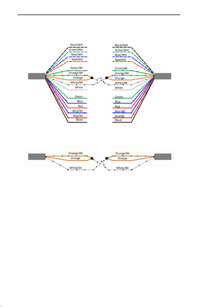
Share2 Wiring Instructions: 15 Wire Harness
Follow the Wiring Diagram in Figure 5 for proper wiring of a
Share2 that utilizes a 15 wire harness. Wiring connections can
be made in a junction box or pedestal body. Strip the Orange/
BK, Orange, and White/BK wires ONLY. Use wire nuts (not
included) to secure the Orange/BK and Orange wires to the
opposing White/BK wire as indicated by the black dots in
Figure 5.
NOTE: Wires with black dotted markings are referenced
with "/BK" and wires with white dotted markings are
referenced with "/WH."
HCS Optional Features User Manual
15
Figure 5: Share2: 15 Wire Harness
Two-station wiring for Share2 (15 Wire Harness)
15 Wire Harness Simplied
15 Wire
Harness
15 Wire
Harness
15 Wire
Harness
15 Wire
Harness
HCS #1 HCS #2
HCS #1 HCS #2
Verify Share2 Function is Working Properly
After wiring is complete use a DC volt meter to test functionality.
Connect the volt meter negative lead to ground, then connect the
volt meter positive lead to the White/BK wire. A measurement
greater than 4V DC should be seen when a vehicle is not connected
or not charging. A voltage less than 1V DC will be measured on the
White/BK wire when a vehicle is charging.
NOTE:
There is a 5 second delay once one vehicle stops
charging before the White/BK wire returns to greater than
4V DC and an additional 10 seconds before full circuit
power will be available to the other vehicle.

HCS Optional Features User Manual
16
Share2 Wiring Instructions: 8 and 10 Wire Harnesses
Follow the Wiring Diagram in Figure 6 for proper wiring of a
Share2 that utilizes an 8 or 10 wire harness. Wiring connections
can be made in a junction box or pedestal body. Strip the Blue,
Brown and White wires ONLY. Use wire nuts (not included) to
secure the Blue and Brown wires to the opposing White wire as
indicated by the black dots in Figure 6.
Do Not Connect Wires marked with an “X”
X
BLACK
YELLOW
ORANGE
RED
GREEN
(GROUND)
BLACK
YELLOW
ORANGE
RED
GREEN
(GROUND)
X
X
X
X
BLUE
BROWN
WHITE
BLUE
BROWN
WHITE
Figure 6: Share2: 8 or 10 Wire Harness
Verify Share2 Function is Working Properly
After wiring is complete use a DC volt meter to test functionality.
Connect the volt meter negative lead to ground, then connect the
volt meter positive lead to the White wire. A measurement greater
than 4V DC should be seen when a vehicle is not connected or
not charging. A voltage less than 1V DC will be measured on the
White wire when a vehicle is charging.
NOTE:
There is a 5 second delay once one vehicle stops
charging before the White wire returns to greater than 4V
DC and an additional 10 seconds before full circuit power
will be available to the other vehicle.
*For 10 wire COSMOS harness, do not connect grey and violet wires.

HCS Optional Features User Manual
17
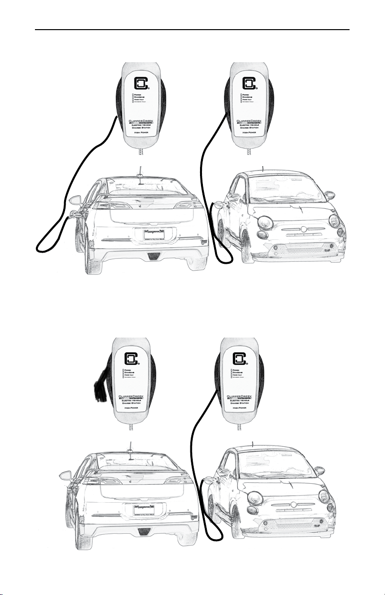
Figure 7: Share2 Connect Vehicle #1
HCS 1 HCS 2
Vehicle 1
Full Circuit Power Available (100%)
Vehicle 2
Not charging (0%)
Share2 Operating Instructions
1. Connect Vehicle #1 to either HCS #1 or HCS #2 with
the corresponding SAE J1772 connector. Vehicle #1
will have access to the full power available through that
circuit.
2. Connect Vehicle #2 to the remaining EVSE with the
SAE J1772 connector. Each vehicle will now have
access to half of the power available through that
circuit.
3. If one vehicle disconnects or completes charging, the
other vehicle will have access to the full circuit power
after 15 seconds.
HCS Optional Features User Manual
18
HCS 1 HCS 2
Vehicle 1
Half Circuit Power Available (50%)
Vehicle 2
Half Circuit Power Available (50%)
Figure 8: Share2 Connect Vehicle #2
HCS 1 HCS 2
Vehicle 1
Not Charging (0%)
Vehicle 2
Full Circuit Power Available (100%)
Figure 9: Share2 One of the Vehicles Disconnects or Completes
Charging

HCS Optional Features User Manual
19
COSMOS Load Management Enabled HCS
The COSMOS option is a Load Management Access Point which
can be connected to a third party load management monitoring and
control system to verify energy usage, optimize energy efciency,
and promote energy conservation.
The COSMOS Load Management Enabled HCS provides two
ways to control energy usage:
1. The Digital Interface
2. The Serial Interface (if the Serial Interface is used it
will take precedence over the Digital Interface)
The COSMOS enabled EVSE will have either a 15, 8 or 10 wire
harness. Please refer to the Wiring Instructions for either the 15 or
8 and 10 wires dependent on the particular harness congurations.
These harnesses have different color wires so it is important to
follow the correct instructions per 15 or 8 and 10 wire counts.
CAUTION: DO NOT STRIP WIRES THAT ARE
UNUSED.
ATTENTION: NE PAS DÉPOUILLER LES FILS
INUTILISÉS.
ATENCIÓN
: NO CORTE LOS CABLES SI NO
LOS ESTÁ UTILIZANDO.

HCS Optional Features User Manual
20
COSMOS Wiring Instructions: 15 Wire Harness
1. Determine whether the Digital Interface will be used
with or without the Serial Interface in the installation.
NOTE: Contact ClipperCreek to obtain an NDA for
documentation describing the Communication Protocol
for the Serial Interface.
2. Conrm power to the EVSE is off and locked out.
3. Connect the appropriate interface wires to the desired
controller. Please refer to Table 2.
Table 2: COSMOSWiring Instructions: 15 Wire Harnesses
Wire Name Input/Output Interface Wire Color Ratings
Isolated Ground Input Black/WH Ground
TxD Output Green/WH
RxD Input Blue/WH
Isolated 3.3-5V Input Red/WH
3.3 - 5V DC, 20mA
Ground Output Green/BK Ground
Load Management 0 Input Orange/BK 5V DC
Load Management 1 Input Orange 5V DC
Open Collector Output 0 Output White/BK
max:24V DC, 5mA
Open Collector Output 1 Output White
max:24V DC, 5mA
Ground Output Green Ground
Blue LED +Source, LED2 Output Blue 5V, 8mA
Red LED +Source, LED1 Output Red 5V, 8mA
B-Button, ChargeGuard Enable Input Blue/BK 5V, 0.5mA
A-Button, External Activate Input Red/BK 5V, 0.5mA
Not Used --- --- Black ---
Serial
Interface
(Isolated
UART)
Digital
Interface
3.3 - 5V DC
Optional
Application
Features
NOTE: Refer to Figure 10. The Black wire is unused.
Other manuals for HCS SERIES
2
This manual suits for next models
2
Table of contents
Other ClipperCreek Batteries Charger manuals

ClipperCreek
ClipperCreek HCS User manual

ClipperCreek
ClipperCreek CS-40 User manual

ClipperCreek
ClipperCreek HCS SERIES User manual

ClipperCreek
ClipperCreek LCS Series User manual

ClipperCreek
ClipperCreek ProMountDuo PMD-10T User manual

ClipperCreek
ClipperCreek CS 3-Phase User manual

ClipperCreek
ClipperCreek CS-100 User manual

ClipperCreek
ClipperCreek LCS Series User manual

ClipperCreek
ClipperCreek HCS SERIES User manual

ClipperCreek
ClipperCreek ProMountDuo PMD-10R User manual


