ClipperCreek CS-100 User manual

ClipperCreek, Inc.
Innovative Infrastructure for
Electric and Hybrid Vehicles
• • • • • • •
Model CS-100
(programmed for 80A continuous)
User Manual

CS-100 User Manual
Page 2
PLEASE NOTE
This user manual includes the latest information at the time of
printing. ClipperCreek, Inc. reserves the right to make changes to
this product without further notice. Changes or modications to this
product by other than an authorized service facility may void the
product warranty.
Contact a Customer Service Representative with any questions about
the use of this product. (877) 694-4194
To view the latest version of this manual please visit
clippercreek.com/installation-manuals
CS-100_80A_Continuous User Manual Version 2, 20190218
All rights reserved. Printed in the USA.
Manual Number: 7004-006-B

CS-100 User Manual
Page 3
CONTENTS
IMPORTANT SAFETY INSTRUCTIONS .................................... 5
Instructions Pertaining to Risk of Fire or Elecric Shock ........... 6
ADDITIONAL SAFETY INFORMATION ................................... 8
FCC INFORMATION .................................................................... 9
OPERATION ................................................................................ 10
Front Panel............................................................................... 11
In Case of Difculty................................................................. 12
FEATURES................................................................................... 13
Personnel Protection System.................................................... 13
Ground Monitoring Circuit...................................................... 13
Auto-Reclosure ........................................................................ 13
Off-Peak Charging ................................................................... 13
Cold Load Pickup .................................................................... 14
External Error Indication ......................................................... 15
Maintenance Current................................................................ 15
INSTALLATION - SERVICE CONNECTIONS ......................... 16
MOUNTING PROCEDURES...................................................... 21
WIRING INSTRUCTIONS.......................................................... 23
Testing After Installation.......................................................... 24
FOR THE SERVICE TECHNICIAN ........................................... 25
Diagnostic ................................................................................ 25
Load Management Disable ...................................................... 25
GFCI Trip................................................................................. 25
Ground Missing ....................................................................... 26
MAINTENANCE ........................................................................ 27
SPECIFICATIONS ....................................................................... 28
LOAD MANAGEMENT INPUTS ............................................. 29
RELAY OUTPUT ......................................................................... 30
CS CABLE WRAP GUIDELINES .............................................. 31
CUSTOMER SUPPORT............................................................... 32
WARRANTY INFORMATION ................................................... 33

CS-100 User Manual
Page 4
ILLUSTRATIONS
Figures
1. The CS-100 Front Panel.......................................................11
2. 220/240V Single Phase .......................................................18
3. 208V 3-Phase, Wye-Connected............................................19
4. 240V 3-Phase, Delta Connected w/Center Tap on
One Leg................................................................................20
5. Wall Mounting of CS-100 ....................................................21
6. CS-100 Installation Template...............................................22
7. Front Door Hidden Latch .....................................................22
8. CS-100 Service Wiring.........................................................23
9. 4-Position Terminal Block....................................................29
10. Wrap the Charge Cable Loosely...........................................31
Tables
1. Front Panel Indicators ..........................................................11
2. PC Board Diagnostic LEDs..................................................26
CS-100 User Manual
Page 5
IMPORTANT SAFETY INSTRUCTIONS
Carefully read these instructions and the charging instructions in
your vehicle owner’s handbook before charging an electric vehicle.
The following symbols may be found in this manual or on labels
afxed to the EVSE:
This means pay particular attention. Notes contain helpful
suggestions.
Cela signie accorder une attention particulière. Les
remarques contiennent des suggestions utiles.
CAUTION: This symbol means be careful. There is
potential of doing something that might result in damage to
the equipment.
ATTENTION: Ce symbole signie être prudent. Vous
êtes capable de faire quelque chose qui pourrait causer des
dommages à l’équipement.
WARNING: This symbol means danger. This is a
situation that could cause bodily injury. Before working
on any electrical equipment, be aware of the hazards
involved with electrical circuitry and standard practices for
preventing accidents.
AVERTISSEMENT: Ce symbole signie un danger.
Vous êtes dans une situation qui pourrait causer des
blessures corporelles. Avant de travailler sur un équipement
électrique, être conscient des dangers présentés par les
circuits électriques et les pratiques courantes de prévention
des accidents.
NOTE
NOTE

CS-100 User Manual
Page 6
Instructions Pertaining to Risk of Fire or Electric Shock
When using the CS, basic electrical safety precautions should be
followed:
• Use this EVSE to charge electric vehicles equipped with an
SAE-J1772TM charge port only. Consult the vehicle owner’s
manual to determine if the vehicle is equipped with the correct
charge port.
• Make certain the EVSE SAE-J1772TM cable is positioned so
it will not be stepped on, tripped over, or otherwise subjected to
damage or stress.
• This product contains no user serviceable parts. Consult the
Customer Support section in this manual for service
information. Do not attempt to repair or service the EVSE.
• Do not operate the EVSE if it or the SAE-J1772TM charge cable
is physically open, cracked, frayed, or otherwise visibly
damaged. Contact a Service Representative for service
immediately. Consult the Customer Support section in this
manual for information on the Service Representative in
the area.
• Not for use in commercial garages where a COMMERCIAL
GARAGE is dened as a facility (or portion thereof) used for
the repair of internal combustion vehicles in which the area
may be classied due to ammable vapors being present (such
as from gasoline).
• Do not place ngers inside of the coupler end of the SAE-
J1772TM charge cable.
• Do not allow children to operate this device. Adult supervision
is mandatory when children are in proximity to an EVSE that is
in use.

CS-100 User Manual
Page 7
Instructions Relatives au Risque d’Incendie ou de Choc Électrique
Lorsque l’utilisation de la CS, précautions fondamentale de
sécurité électrique doivent être suivies:
• Utilisez cette EVSE pour charger les véhicules électriques
équipés d’un SAE-J1772TM port de recharge seulement.
Consultez le manuel du propriétaire du véhicule an de
déterminer si le véhicule est équipé d’un correcte port de
recharge.
• Assurez-vous que le SAE-J1772TM câble de recharge sur la
EVSE est positionné de telle sorte qu’il ne sera pas piétiné,
accroché plus de, ou autrement endommagé ou de subir le
stress.
• Ce produit ne contient aucune pièce réparable par l’utilisateur.
Consultez la section Support à la Clientèle dans ce manuel pour
obtenir des informations de service. N’essayez pas de réparer
ou d’entretenir la EVSE vous-même.
• Ne faites pas fonctionner votre station ou le câble de recharge
si elles sont physiquement ouverte, ssuré, efloché, ou
autrement visiblement endommagé. Contactez votre
représentant du service pour service immédiatement. Consultez
la section Support à la clientèle dans ce manuel pour obtenir
des informations sur le représentant du service dans votre région.
• Ne pas utiliser dans les garages commerciaux où un garage
commercial est déni comme une installation (ou une partie)
utilisé pour la réparation de véhicules à combustion interne
dans lequel la zone peut être classée en raison de vapeurs
inammables étant présents (Tels que de l’essence).
• Ne posez pas les doigts à l’intérieur de l’extrémité du SAE-
J1772TM coupleur du câble de recharge.
• Ne pas laisser les enfants utiliser cet appareil. Supervision d’un
adulte est obligatoire lorsque des enfants sont à proximité
d’une EVSE qui est en cours d’utilisation.

CS-100 User Manual
Page 8
ADDITIONAL SAFETY INFORMATION
WARNING:
Turn off input power to the EVSE at the circuit
breaker panel before servicing or cleaning the unit.
AVERTISSEMENT: Couper l’alimentation d’entrée à
votre EVSE sur le panneau de disjoncteur avant de nettoyer
ou de réparer l’appareil.
VENTILATION: Some electric vehicles require an
external ventilation system to prevent the accumulation
of hazardous or explosive gases when charging indoors.
Consult the vehicle owner’s manual to determine if the
vehicle requires ventilation during indoor charging.
VENTILATION: Certains véhicules électriques
nécessitent un système de ventilation externe pour éviter
l’accumulation de gaz explosifs ou dangereux lors
de la charge à l’intérieur. Consultez le manuel du
propriétaire du véhicule pour déterminer si votre véhicule
nécessite une ventilation quand le recharge en salle.
Vehicles which conform to the SAE-J1772TM standard for
communication can inform the EVSE that they require an
exhaust fan. The EVSE is not equipped to control
ventilation fans. Do not charge the EV with the EVSE if
ventilation is required.
Véhicules qui sont conformes à la norme SAE-J1772TM
de communication peuvent informer la EVSE qu’ils
nécessitent un ventilateur d’extraction. Le EVSE n’est pas
équipé pour contrôler les ventilateurs. Ne chargez
pas le véhicule avec les EVSE si la ventilation est nécessaire.
CAUTION: DO NOT CHARGE an EV indoors if
it requires ventilation. Contact a Service Representative.
ATTENTION: NE PAS RECHARGER un véhicule
à l’intérieur si il nécessite une ventilation. Contactez votre
représentant de service pour plus d’informations.
Save these instructions for future reference.
Conservez ces instructions pour référence future.
NOTE
NOTE
NOTE
NOTE

CS-100 User Manual
Page 9
FCC INFORMATION
This device complies with Part 15 of the FCC rules. Operation
is subject to the following two conditions: (1) This device may
not cause harmful interference, and (2) This device must accept
any interference received, including interference that may cause
undesired operation.
This product has been designed to protect against Radio Frequency
Interference (RFI). However there are some instances where high
powered radio signals or nearby RF-producing equipment (such as
digital phones, RF communications equipment, etc.) could affect
operation.
If interference to the EVSE is suspected, we suggest the following
steps be taken before consulting a ClipperCreek Sales and Service
Representative for assistance:
1. Reorient or relocate nearby electrical appliances or equipment
during charging.
2. Turn off nearby electrical appliances or equipment during
charging.
CAUTION: Changes or modications to this product
by other than an authorized service facility may void FCC
compliance.
ATTENTION: Modications apportées à ce produit par
qui conque autre qu’un centre de service autorisé
peut annuler la conformité FCC.

CS-100 User Manual
Page 10
OPERATION
The CS-100 is a conductive EVSE that provides the electric
vehicle (EV) user with a safe and manageable link between the
power grid and the electric vehicle.
Remove the charging connector from its holder, and plug it into the
vehicle’s charge port. If there is a mechanical latch that holds the
connector rmly while charging, be sure the latch has “clicked”
into place. Normally, the vehicle will immediately request a
charge, the Green CHARGING light will come on, and charging
will begin. After an average driving day, it will require a few hours
to recharge completely. Charging overnight is the most convenient
way to ensure the vehicle’s full range will be available for the next
day.
If the vehicle has stopped charging, the Green CHARGING light
will be off. Remove the cable and the vehicle is ready to use. If the
charging is still in progress, rst push the START/STOP button on
the CS-100 front panel. The charging light will start blinking and
the EV charge connector can be removed.

CS-100 User Manual
Page 11
Front Panel
The front panel of the CS-100 has one GREEN and one RED light
to indicate the status of the unit. The operational state of the unit
can be determined by looking at the panel lights and comparing
them with Table 1 below.
Table 1. Front Panel Indicators
(Green) (Red) Status of CS-100
CHARGING PROTECTION
OFF OFF - Vehicle is not connected
-
or
vehicle is not requesting charge
ON OFF - Vehicle is charging at 80A
- The ground fault is tripped
OFF ON -
or
the ground is missing
-
or
service is required
ON ON - There is a problem on the vehicle
- charging interrupted by the user
blink OFF -
or
charging disabled by external timer
-
or
unit is in Cold Load Pickup
Figure 1. The CS-100 Front Panel
Status of CS EVSE

CS-100 User Manual
Page 12
In Case of Difculty
ClipperCreek recognizes that this EVSE will be heavily relied
upon to charge an electric vehicle for daily transportation needs.
Therefore, every effort will be made to restore service should
problems arise.
In the event of a problem, charging will stop and the Red
PROTECTION light will turn on. If this happens, please try the
two simple steps below before calling a Service Representative.
1. Remove the cable connector from the vehicle socket. The Red
PROTECTION light may turn off. If it does turn off, plug the
connector back into the socket, and see if charging begins
normally.
2. If the Red PROTECTION light does not go out when the
connector is removed, be sure the connector is removed
from the vehicle socket and switch off power at the circuit
breaker feeding power to the CS-100. Wait a few seconds and
switch the circuit breaker back on again. If the Red
PROTECTION light does not turn on, re-connect the cable to
the vehicle. Charging should begin normally. If charging does
not begin, or if the Red PROTECTION light turns back on, call
a Service Representative.
The information obtained by following the above steps will help
the Service Representative determine what the problem is and how
best to get the EVSE operational again as quickly as possible.

CS-100 User Manual
Page 13
FEATURES
The following features are supported by the CS-100:
Personnel Protection System: Ground Fault protection with
Self-Testing and Auto-Reclosure (see below), no manual resetting
or testing is necessary.
Ground Monitoring Circuit: Constantly checking for the
presence of a Safety Ground connection.
Auto-Reclosure: If a problem occurs that interrupts charging, the
unit will automatically clear all error indications after 5 minutes,
and attempt to begin charging again. If the problem is immediately
sensed a second time, it will wait another 5 minutes and try again.
This process will repeat several times, at which point power
will be removed and no further attempt will be made. The Red
PROTECTION light on the front panel will be on.
This feature helps ensure that the vehicle will be charged and
ready for use when needed. Temporary problem indications
such as ground-faults or utility power surges can be overcome
automatically without the need for the user to manually re-initiate
charging.
Off-Peak Charging: For this feature, an external timer must be
installed (purchased separately). A utility may also install a special
Time-of-Use meter to provide special rates for Off-Peak Charging.
If a timer is installed, it is not necessary to wait until late evening
to plug the CS-100 charge connector into the vehicle. The
CS-100
may be connected to the vehicle at any time. Even though the
vehicle may immediately request a charge, the timer will cause
the CS-100 to delay energizing the cable until the specied time
period. With this feature, the Green CHARGING light will blink
while the vehicle waits for the timer to allow charging.

CS-100 User Manual
Page 14
Making the best use of the Off-Peak Charging feature will require
the following:
1. Installation of a Time-Of-Use meter by the electric utility.
2. Installation of a clock/timer to allow the CS-100 to charge only
during Off-Peak hours.
3. Connecting the timer’s control wire to the High/Off pin on the
4-position terminal block. Refer to Figure 9, CS Service
Wiring to identify the correct pin.
If this feature is desired, please call the local utility to be sure the
Time-of-Use meter is available in the area before having the timer
installed. Technical information to help connect the timer to the
CS can be found in the Load Management Inputs section of this
manual.
NOTE: Many vehicles are equipped with programmable
timers for the purpose of setting the charge time independent
of the EVSE.
Cold Load Pickup: This feature is built-in to the CS-100,
but will only be apparent when the utility power fails during
charging. If the charging connector is still plugged into the vehicle
when utility power is restored, the Green CHARGING light will
blink and the unit will not energize the cable for a random time
between 2 and 12 minutes. This is to prevent the utility’s grid from
experiencing a large surge at turn-on, allowing electric vehicles in
the area to begin drawing current at random times rather than all at
once.
NOTE: The vehicle does not need the owner’s attention after a
power outage. The CS-100 will automatically resume charging
when power is restored.

CS-100 User Manual
Page 15
External Error Indication: Whenever the Red PROTECTION
light is on, a relay on the board will provide a contact closure
that can be used to remotely indicate that a problem exists. A
eet vehicle yard, for example, could use this feature to light a
lamp or ring a bell in the main ofce, indicating that a vehicle
has a charging problem. This early warning helps assure that each
vehicle will be properly charged and ready for use when needed.
The two rightmost pins on the 4-position terminal block are the
relay contacts for the External Error Indication. More information
on the Relay Output feature can be found in the Load Management
Inputs section of this manual.
Maintenance Current: If the unit is set up for Off-Peak
Charging as described above, normal charging current cannot be
drawn by the vehicle until the Off-Peak hours. However, the CS-
100 can be set up to allow a minimum amount of current while
waiting for the timer to allow full-rate charging. This is known
as Maintenance Current, used for all power needs on the vehicle
except charging the main battery pack. An example would be
preheating the cab, or keeping the auxiliary battery topped off. As
in the Off-Peak mode above, the Green CHARGING light will
ash if the vehicle is connected and waiting for the timer to allow
charging. The contactor will close immediately to supply this small
amount of power, but the main battery pack will not be allowed to
charge.
The Maintenance Current feature can be selected by connecting
the Timer’s control wire to the High/Low pin on the 4-terminal
Terminal Block. Connecting to the High/Off pin will remove all
power from the vehicle until the Off-Peak Charging time arrives.
Refer to Figure 9, CS Service Wiring to identify the correct pin.
The other two pins on the terminal block are the relay contacts for
the External Indicator.

CS-100 User Manual
Page 16
INSTALLATION - SERVICE CONNECTIONS
CAUTION: This is a single-phase device. DO NOT
connect all 3 phases of a 3-phase feed! Any two phases of
a 3-phase wye-connected feed can be used. The
center-point of the 3 phases (usually used as Neutral) must
be grounded somewhere in the system. A current-carrying
Neutral is not needed by the CS-100. Only LINE 1, LINE
2, and GROUND are required, as shown in Figure 3.
CAUTION: The two phases used must each measure
120V to Neutral. Earth Ground must be connected to
Neutral at only one point, usually at the Service Entry
Breaker Panel.
CAUTION: If a 240V 3-phase feed is from a Delta-
connected secondary, the leg used must have a center-tap.
That tap must be Grounded. Only the two phases either side
of the center-tapped leg can be used. See Figure 4.
Caution: Warranty is void if this unit is wired
improperly.
WARNING: Only a qualied electrician should perform
the installation. The installation must be performed in
accordance with all local electrical codes and ordinances.
Only 3 wires are connected, but care must be taken that the service
transformer secondary connection is denitely known, and the
3 wires from the main circuit breaker panel are connected and
labeled correctly. Figures 2, 3, and 4show the most common
service transformer secondary wiring formats.

CS-100 User Manual
Page 17
Notice that L1, L2 & Ground are labeled on each diagram. These
transformer outputs correspond to the same inputs on the CS-100.
Each of the two 3-phase diagrams shows an L3 output, which is
not used. Do not connect all three phases of a 3-phase secondary
to the CS. This is a single-phase device.
The Neutral at the service panel must be connected to earth
ground somewhere in the system on any of the three connection
arrangements. Ground-fault protection is not possible unless the
Neutral (center-tap on the service transformer) is connected to an
earth ground. If no ground is provided by the electrical service, a
grounding stake must be driven into the ground nearby, following
local electrical codes. The grounding stake must be connected to
the ground bar in the main breaker panel, and Neutral connected to
ground at that point.
WARNING: Local electrical codes must always be
followed when installing the grounding stake.

CS-100 User Manual
Page 18
The following diagrams illustrate the 3 service transformer
secondary connections most common in the United States.
Figure 2. 220/240V Single Phase

CS-100 User Manual
Page 19
Figure 3. 208V 3- Phase, Wye-Connected
With a wye-connected secondary, any two of the legs can
be used to provide 208V to the CS-100. For example, L1
& L2, or L1 & L3, or L2 & L3. Leave the unused leg
open. DO NOT connect it to a Neutral bar or to Ground.
Be sure the center point is grounded to earth somewhere
in the system.
NOTE:
CS-100 User Manual
Page 20
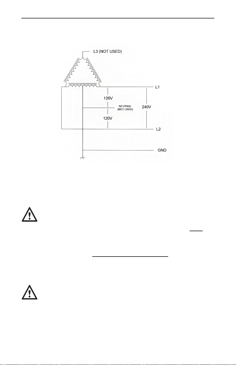
CAUTION: With the delta connection, one leg must
be center-tapped, and only the two phases on either side
of the center tap can be used. The two phases must both
measure 120V to neutral. The third line (L3) of the delta
is 208V, with respect to neutral, and is sometimes referred
to as a “stinger”. Do not use this third line! Consult the
transformer manufacturer’s literature to be sure the single
leg can supply the required power.
CAUTION: A 3-phase delta-connected transformer
secondary without a center-tap on one leg is not usable
with the CS-100. No “neutral” point is available to be
connected to ground for ground-fault protection, and the
CS-100 will not allow the contactor to close if it does
not sense the presence of a ground wire connected to a
“neutral” point on the transformer secondary.
Figure 4.
240V 3-Phase, Delta-Connected, w/Center-Tap on One Leg
Table of contents
Other ClipperCreek Batteries Charger manuals

ClipperCreek
ClipperCreek LCS Series User manual

ClipperCreek
ClipperCreek HCS SERIES User manual

ClipperCreek
ClipperCreek CS-40 User manual

ClipperCreek
ClipperCreek CS 3-Phase User manual

ClipperCreek
ClipperCreek HCS SERIES User manual

ClipperCreek
ClipperCreek LCS Series User manual

ClipperCreek
ClipperCreek ProMountDuo PMD-10R User manual

ClipperCreek
ClipperCreek HCS User manual

ClipperCreek
ClipperCreek EV Series User manual

ClipperCreek
ClipperCreek ProMountDuo PMD-10T User manual


