CLIVET HRV-DXL-2-XMi D1500 User manual

HRVӣCXLӣӣXMe
SerieԗR[kc`CӣC
PER L’INSTALLAZIONE,
L’USO E MANUTENZIONE
FOR INSTALLATION,
USE AND MAINTENANCE
C
ӣVRH
S
M
XӣӣLX
C
C`ck[Rԗ
S
erie
e
M
Cӣ
TENZIONEMANU
ALLAZIONE,
T
TA
’INS
L
L’
D
MAINTENANCE
TION,
ALLA
T
TA
R INS
’USO E
L
L’
PER
L
USE AN
D
OF
M0WP00001-01
BT20M080I--01
M0WP00002-01
BT20M080GB-01

IMPORTANTE
PRIMA DI COMPIERE QUALUNQUE OPERAZIONE
RIGUARDANTE LA MACCHINA LEGGERE
ATTENTAMENTE, COMPRENDERE E SEGUIRE
TUTTE LE ISTRUZIONI DEL PRESENTE MANUALE
IMPORTANT
BEFORE PERFORMING ANY OPERATION OF THE
MACHINE CAREFULLY READ,
UNDERSTAND AND FOLLOW
ALL INSTRUCTIONS LISTED IN THIS MANUAL
pag. 2
INDICE
1 - 1 - SIMBOLOGIA UTILIZZATA................................................................3
2 - AVVERTENZE E REGOLE GENERALI .................................................3
DICHIARAZIONE DI CONFORMITÀ “CE.....................................................5
3 - IDENTIFICAZIONE UNITÀ ....................................................................6
4 - CARATTERISTICHE TECNICHE............................................................7
4.1 Caratteristiche generali......................................................................7
4.2 Accessori...........................................................................................7
4.3 Dati tecnici unità ................................................................................8
4.4 Orientamento unità............................................................................9
4.5 Funzionalità principali......................................................................10
4.6 Dimensioni e pesi ...........................................................................11
4.7 Curve caratteristiche ......................................................................12
4.8 Livelli di rumorosità sonora..............................................................13
4.9 Accessori.........................................................................................14
4.9.1 Resistenza elettrica di pre-riscaldamento - PRE-DX.......................14
4.9.2 Sistema di sanificazione - BIOX-DX................................................14
5- TRASPORTO.........................................................................................15
6 - SCARICO..............................................................................................15
6.1 Controllo al ricevimento...................................................................15
6.2 Sollevamento e Movimentazione.....................................................15
6.3 Stoccaggio.......................................................................................15
7 - INSTALLAZIONE E MESSA IN SERVIZIO...........................................16
7.1 Definizioni........................................................................................16
7.2 Norme di sicurezza .........................................................................16
7.3 Informazioni preliminari ...................................................................17
7.4 Luogo d'installazione .......................................................................17
7.5 Posizionamento della macchina......................................................18
7.6 Collegamento ai canali ....................................................................19
7.7 Collegamenti idraulici scarichi condensa.........................................19
7.8 Sezione batteria ad espansione diretta ..........................................20
7.8.1 Serraggio.........................................................................................21
7.8.2 Effettuare le saldature .....................................................................22
7.8.3 Isolamento delle tubazioni...............................................................22
8 - COLLEGAMENTI ELETTRICI ............................................................23
8.1 Controllo e regolazione elettronica dell’unità...................................23
8.2 Schema elettrico..............................................................................24
8.2.1 Layout quadro elettrico - Modulo DX ..............................................24
8.2.2 Schema elettrico..............................................................................25
8.2.3 Schema elettrico addizionale...........................................................26
8.3 Settaggio della scheda DX ..............................................................28
8.4 Settaggi indirizzi del sistema e indirizzi di rete ................................29
8.5 Indicazioni settaggio scheda ...........................................................30
8.6 Codici errore e Query ......................................................................35
8.7 Aspetto del comando remoto a cavo...............................................37
8.8 Sistema BIOX-DX ...........................................................................41
9 - CONTROLLI PRIMA DELL'AVVIAMENTO ...........................................41
10 - MANUTENZIONE ORDINARIA...........................................................42
10.1 Avvertenze.......................................................................................42
10.2 Controlli mensili ...............................................................................42
10.2.1 Verifica della sezione filtrante..........................................................42
10.3 Controlli semestrali..........................................................................43
10.4 Controlli annuali...............................................................................44
11- LOCALIZZAZIONE DEI GUASTI..........................................................45
12 - SMALTIMENTO ..................................................................................47
13 - PARTI DI RICAMBIO...........................................................................48
INDEX
1 - SYMBOLS USED ....................................................................................3
2 - WARNINGS AND GENERAL RULES.....................................................3
“EC” DECLARATION OF CONFORMITY.....................................................5
3 - IDENTIFICATION OF THE UNIT ...........................................................6
4 - TECHNICAL SPECIFICATIONS .............................................................7
4.1 General characteristics......................................................................7
4.2 Options ..............................................................................................7
4.3 Unit technical data .............................................................................8
4.4 Imot configuration ..............................................................................9
4.5 Main logic control ...........................................................................10
4.6 Dimensions and weights..................................................................11
4.7 Characteristic curves .......................................................................12
4.8 Sound power levels .........................................................................13
4.9 Options ............................................................................................14
4.9.1 PRE and post-heating electric coil - PRE-DX..................................14
4.9.2 Purifying system - BIOX-DX ............................................................14
5- TRANSPORT .........................................................................................15
6 - UNLOADING .........................................................................................15
6.1 Checks upon receipt........................................................................15
6.2 Hoisting and handling ......................................................................15
6.3 Storage ............................................................................................15
7 - INSTALLATION AND START UP .........................................................16
7.1 Definitions........................................................................................16
7.2 Safety Standards .............................................................................16
7.3 Preliminary information ...................................................................17
7.4 nstallation location ...........................................................................17
7.5 Positioning of the machine ..............................................................18
7.6 Connection to the ducts...................................................................19
7.7 Hydraulic connections .....................................................................19
7.8 DX coil section.................................................................................20
7.8.1 Tightening........................................................................................21
7.8.2 Welding joint cautions......................................................................22
7.8.3 Insulating the refrigerant tubing .......................................................22
8 - ELECTRIC CONNECTIONS .................................................................23
8.1 Electronic control and adjustment of the Unit ..................................23
8.2 Wiring diagram ................................................................................24
8.2.1 Electric box layout - MODULE DX...................................................24
8.2.2 Electric layout ..................................................................................25
8.2.3 Additional electrical diagram............................................................26
8.3 Application control ...........................................................................28
8.4 System address and network address setting ..............................29
8.5 Mainboard code indication label ......................................................30
8.6 Error Codes and Query ..................................................................35
8.7 Wired remote controller outlook.......................................................37
8.8 BIOX-DX system ............................................................................41
9 - CONTROLS BEFORE START-UP........................................................41
10 - ROUTINE MAINTENANCE .................................................................42
10.1 Warnings .........................................................................................42
10.2 Monthly checks ..............................................................................42
10.2.1 Check the range filtering section .....................................................42
10.3 Half-yearly controls..........................................................................43
10.4 Yearly checks ..................................................................................44
11 - IDENTIFYING BREAKDOWNS...........................................................45
12 - DISPOSAL ..........................................................................................47
13 - SPARE PARTS ...................................................................................48
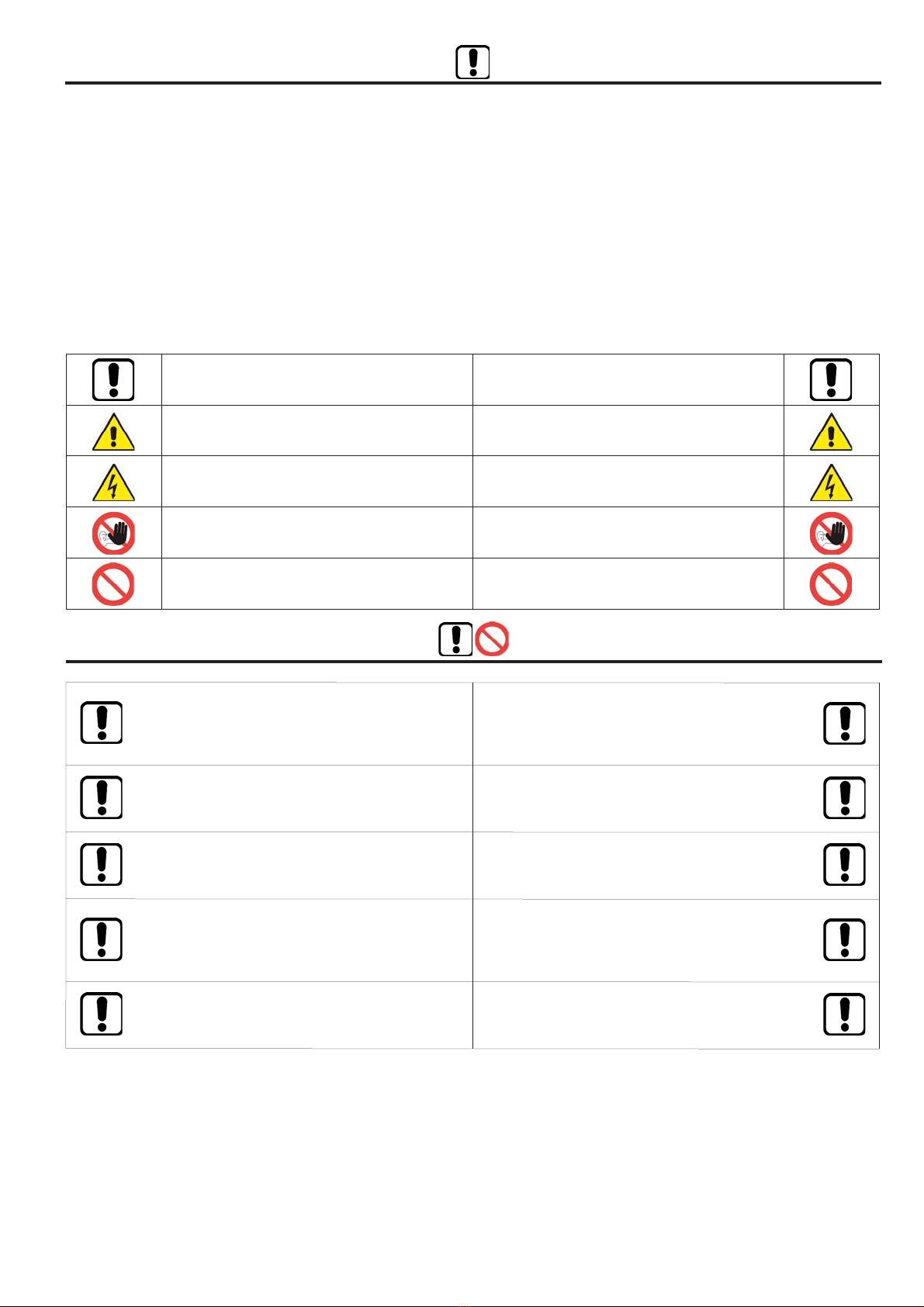
AVVERTENZA WARNING
PERICOLO DANGER
PERICOLO RISCHIO DI SCOSSE ELETTRICHE DANGER RISK OF ELECTRIC SHOCK
ATTENZIONE SOLO PERSONALE AUTORIZZATO ATTENTION ONLY AUTHORISED STAFF
DIVIETO PROHIBITION
La macchina è stata progettata e costruita in accordo alle norme vigenti
ed è quindi dotata di sistemi di prevenzione e protezione per i rischi di na-
tura meccanica ed elettrica che possono riguardare l’operatore o l’utiliz-
zatore. Vi sono tuttavia dei rischi residui che possono presentarsi durante
il trasporto, l’installazione, l’uso o la manutenzione. Tali rischi possono es-
sere ridotti seguendo scrupolosamente le istruzioni del manuale, utiliz-
zando gli adeguati dispositivi di protezione individuali e rispettando le
vigenti norme di sicurezza.
Le indicazioni più importanti riguardanti la sicurezza e il corretto utilizzo
della macchina sono accompagnate da alcuni simboli per renderle più evi-
denti:
Questo libretto d'istruzione è parte integrante dell'apparecchio e di conse-
guenza deve essere conservato con cura e dovrà SEMPRE accompagnare
l'apparecchio anche in caso di sua cessione ad altro proprietario o utente
oppure di un trasferimento su un altro impianto. In caso di suo danneggia-
mento o smarrimento richiederne un altro esemplare alla Ditta Costruttrice.
This instruction book is an integral part of the appliance and as a
consequence must be kept carefully and must ALWAYS accom-
pany the appliance even if transferred to other owners or users or
transferred to another plant. If damaged or lost, request another
copy from the Manufacturer.
Gli interventi di riparazione o manutenzione devono essere eseguiti da
personale autorizzato o da personale qualificato secondo quanto previsto
dal presente libretto. Non modificare o manomettere l'apparecchio in
quanto si possono creare situazioni di pericolo ed il costruttore dell'appa-
recchio non sarà responsabile di eventuali danni provocati.
Repair and maintenance interventions must be carried out by au-
thorised staff or staff qualified according to that envisioned by this
book. Do notmodify or tamper with the appliance as dangerous
situations can be created and the appliance manufacturer will not
be liable for any damage caused.
Dopo aver tolto l'imballo assicurarsi dell'integrità e della completezza del
contenuto. In caso di non rispondenza rivolgersi alla Ditta che ha venduto
l'apparecchio.
After having removed the packaging ensure the integrity and com-
pleteness of the content. If this is not the case, contact the
Company that sold the appliance.
L'installazione degli apparecchi deve essere effettuata da impresa abilitata
che, a fine lavoro, rilasci al proprietario la dichiarazione di confomità di in-
stallazione realizzata a regola d'arte, cioè in ottemperanza alle Norme vi-
genti ed alle indicazioni fornite in questo libretto.
The appliances must be installed by enabled companies which, at
the end of the job issues a declaration of conformity regarding in-
stallation to the owner, i.e. in compliance with the Standards in force
and the indications supplied in this book.
È esclusa qualsiasi responsabilità contrattuale ed extracontrattuale della
Ditta Costruttrice per danni causati a persone, animali o cose, da errori di
installazione, di regolazione e di manutenzione o da usi impropri.
Any contractual or extracontractual liability of the Manufacturer is
excluded for injury/damage to persons, animals or objects owing
to installation, regulation and maintenance errors or improper use.
2 - AVVERTENZE E REGOLE GENERALI 2 - WARNINGS AND GENERAL RULES
1 - SIMBOLOGIA UTILIZZATA 1 - SYMBOLS USED
The machine has been designed and constructed according to the cur-
rent norms and consequently with mechanical and electrical safety de-
vices designed to protect the operator or user from possible physical
damage.
Residual risks during use or in some intervention procedures on the
device are however present. Such risks can be reduced by
carefully following manual procedures, using the suggested individual
protection devices and respecting the legal and safety norms in force.
The most important information concerning safety and proper use of
the machine are accompanied by some symbols to make them highly
visible:
pag. 3
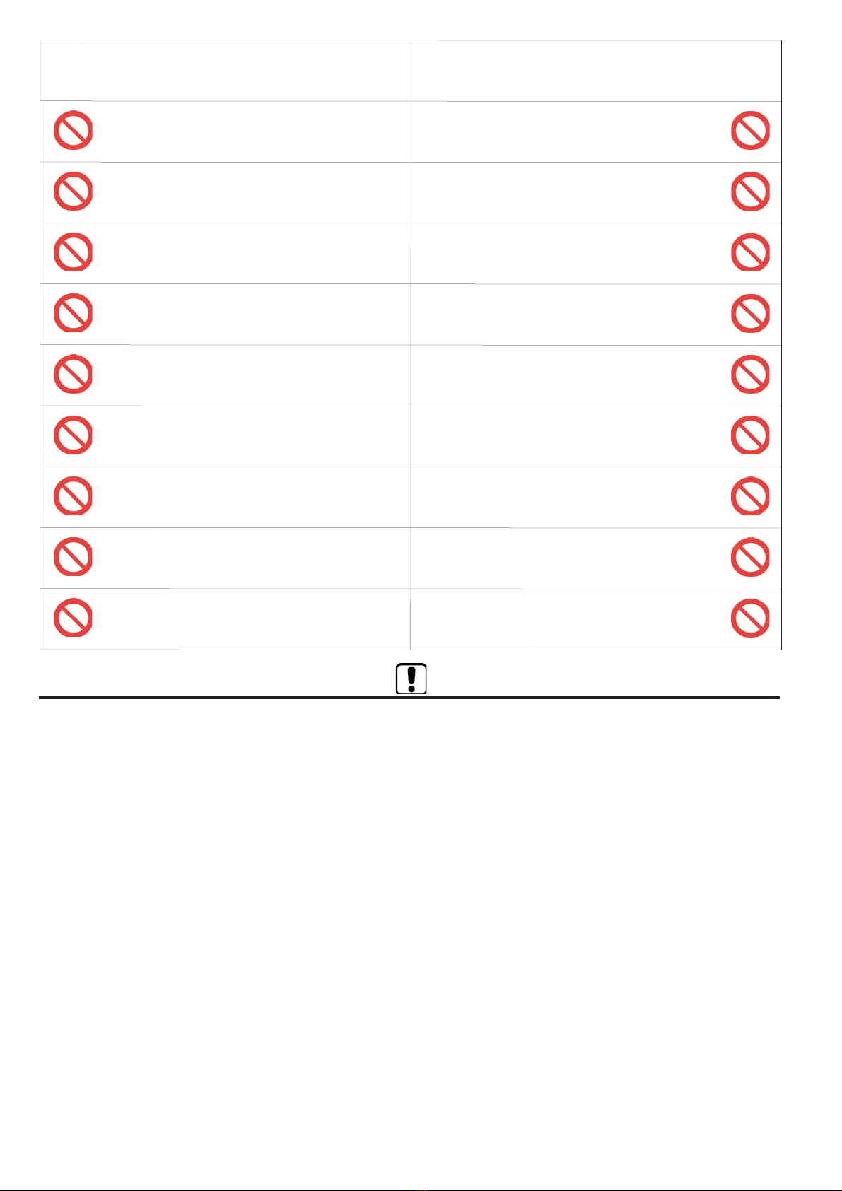
Ricordiamo che l'utilizzo di prodotti che impiegano energia elettrica ed acqua, comporta
l'osservanza di alcune regole fondamentali di sicurezza quali:
We remind you that the use of products that employ electrical energy and
water requires that a number of essential safety rules be followed, including:
È vietato l'uso dell'apparecchio ai bambini e alle persone inabili non as-
sistite.
This appliance must not be used be children and unaided disa-
bled persons.
È vietato toccare l'apparecchio se si è a piedi nudi e con parti del corpo
bagnate o umide.
It is prohibited to touch the appliance when you are barefoot and
with parts of the body that are wet or damp.
È vietata qualsiasi operazione di manutenzione o di pulizia, prima di
aver scollegato l'apparecchio dalla rete di alimentazione elettrica posi-
zionando l'interruttore generale dell'impianto su "spento".
It is prohibited to perform any maintenance or cleaning opera-
tion before having disconnected the appliance from the
mains electricity network, by positioning the plant master switch
at "off"
È vietato modificare i dispositivi di sicurezza o di regolazione senza l'au-
torizzazione e le indicazioni del costruttore dell'apparecchio.
It is prohibited to modify the safety or adjustment devices wi-
thout the manufacturer’s authorisation and precise instructions
È vietato tirare, staccare, torcere i cavi elettrici fuoriuscenti dall'apparec-
chio, anche se questo è scollegato dalla rete di alimentazione elettrica.
It is prohibited to pull, detach or twist the electrical cables co-
ming from the unit even if it is disconnected from the electrical
mains
È vietato salire con i piedi sull'apparecchio, sedersi e/o appoggiarvi
qualsiasi tipo di oggetto.
It is prohibited to climb onto the unit, sit on it and/or rest any
type of object on it.
È vietato spruzzare o gettare acqua direttamente sull'apparecchio.
It is prohibited to spray or jet water directly onto the unit.
È vietato aprire gli sportelli di accesso alle parti interne dell'apparecchio,
senza aver prima posizionato l'interruttore generale dell'impianto su
"spento" .
It is prohibited to open the doors for accessing the internal parts
of the appliance without first having switched off the master
switch of the "system".
È vietato disperdere, abbandonare o lasciare alla portata di bambini il
materiale dell'imballo in quanto può essere potenziale fonte di pericolo.
It is prohibited to disperse, abandon or leave the packing mate-
rials within the reach of children, as they are a potential
source of danger
NOTE IMPORTANTI IMPORTANT NOTES
Le unità sono progettate e costruite esclusivamente per:
- installazioni interne, salvo adottare idonei accessori che ne con-
sentano l’installazione all’aperto;
- per il trattamento aria degli ambienti civili, incompatibili con gas
tossici, esplosivi, infiammabili e corrosivi (incluse atmosfere con
cloro e salsedine).
Quindi se ne fa esplicito divieto di utilizzo in quegli ambienti dove
l'aria risulti mescolata e/o alterata da altri composti gassosi e/o
particelle solide.
L'utilizzo per scopi diversi da quelli previsti, e non conformi a
quanto descritto in questo manuale, farà decadere automatica-
mente qualsiasi responsabilità diretta e/o indiretta della Ditta Co-
struttrice e dei suoi Distributori.
Poiché la Ditta Costruttrice è costantemente impegnata nel con-
tinuo perfezionamento di tutta la sua produzione, le caratteristi-
che estetiche e dimensionali, i dati tecnici, gli equipaggiamenti e
gli accessori, possono essere soggetti a variazione.
Per tale motivo il produttore si riserva di apportare qualsiasi mo-
difica senza preavviso.
The units are designed and built exclusively for:
- internal installation, except to use specific option for outdoor
installation;
- for air traitment in the civil environments, incompatible with
toxic, explosive, inflammable and corrosive (chlorinated and sa-
line included) gases.
Therefore it cannot be used in those environments where the air
is mixed and/or altered by other gaseous composites and/or solid
particles.
The use of the same for different purposes from those envisioned,
not conform to that described in this manual, will make any direct
and/or indirect liability of the Manufacturer automatically become
null and void.
As our Company is constantly involved in the continuous impro-
vement of its production, aesthetic characteristics and dimen-
sions, technical data, equipment and accessories can be subject
to variation. For this reason the manufacturer reserves the right
to make any changes without prior notice.
pag. 4
DECLARATION OF CONFORMITY UKCA
DICHIARAZIONE DI CONFORMITÀ UKCA
KONFORMITÄTSERKLÄRUNG UKCA
DECLARATION DE CONFORMITE UKCA
DECLARACIÓN DE CONFORMIDAD UKCA
CLIVET S.P.A. - Via Camp Lonc, 25 - Z.I. VILLAPAIERA - 32030 FELTRE (BL) –ITALIA
Cap.Soc. Eur 20.000.000 i.v. C.F. e Reg.Impr. BL n°.00708410253 –R.E.A. n°.66577 –P.I. /VAT:IT 00708410253
Tel. +39 0439 3131 - Fax +39 0439 313300 –Web: www.clivet.it Mail: [email protected] PEC: amministrazion[email protected] - Registro A.E.E. IT08020000001697
WE DECLARE UNDER OUR SOLE RESPONSIBILITY THAT THE MACHINE
DICHIARIAMO SOTTO LA NOSTRA SOLA RESPONSABILITÀ CHE LA MACCHINA
WIR ERKLÄREN EIGENVERANTWORTLICH, DASS DIE MASCHINE
NOUS DÉCLARONS SOUS NOTRE SEULE RESPONSABILITÉ QUE LA MACHINE
ELFABRICANTE DECLARA BAJO SU EXCLUSIVA RESPONSABILIDAD QUE LA MÁQUINA
CATEGORY
CATEGORIA
KATEGORIE
CATEGORIE
CATEGORIA
TYPE /TIPO /TYP /TYPE /TIPO
- COMPLIES WITH THE FOLLOWING UKCA DIRECTIVES, INCLUDING THE MOST RECENT AMENDMENTS, AND THE RELEVANT NATIONAL
HARMONISATION LEGISLATION CURRENTLY IN FORCE:
- RISULTA IN CONFORMITÀ CON QUANTO PREVISTO DALLE SEGUENTI DIRETTIVE UKCA, COMPRESE LE ULTIME MODIFICHE, E CON LA
RELATIVA LEGISLAZIONE NAZIONALE DI RECEPIMENTO:
- DEN IN DEN FOLGENDEN UKCA-RICHTLINIEN VORGESEHENEN VORSCHRIFTEN, EINSCHLIEßLICH DER LETZTEN ÄNDERUNGEN, SOWIE DEN
ANGEWANDTEN LANDESGESETZEN ENTSPRICHT:
- EST CONFORME AUXDIRECTIVES UKCA SUIVANTES, YCOMPRIS LES DERNIÈRES MODIFICATIONS, ET ÀLA LÉGISLATION NATIONALE
D'ACCUEIL CORRESPONDANTE:
- ES CONFORME ALAS SIGUIENTES DIRECTIVAS UKCA, INCLUIDAS LAS ÚLTIMAS MODIFICACIONES, YALA RELATIVA LEGISLACIÓN NACIONAL
DE RECEPCIÓN:
2006/42/EC Supply of Machinery (Safety) Regulation 2008
2014/30/UE Electromagnetic Compatibility Regulations 2016
2011/65/UE 2015/65/UE RoHS -S.I. 2012 No. 3032
2009/125/CE The Eco-design for Energy-Related Products and Energy Information (Amendment) (EU Exit) Regulations 2019
-Unit manufactured and tested according to the followings Standards:
-Unità costruita e collaudata in conformità alle seguenti Normative:
-Unitéconstruiteettestéeenconformitéavecles Réglementations suivantes
-Unidad construida y probada de acuerdo con las siguientes Normativas
-Gebautes und geprüftes Gerät nach folgenden Normen
BS EN ISO 12100 :2010 BS EN 55014-1 :2017 BS EN 55014-2 :2015
BS EN IEC 61000-3-2 :2014 BS EN IEC 61000-3-3 :2013
BS EN 60335-1 :2012+A11 BS EN 60335-2-80 :2003+A1+A2
BS CEI EN 60204-1 :2006-09 BS EN 62233 :2008
BS UNI EN ISO 16890-1 :2017
BS UNI EN 13053 :2011 BS UNI EN 308 :1998 AMCA 201-02 :2007
-Responsible to constitute the technical file is the companyn°. IT03074850235 and registered at the Chamber of Commerce of Verona Italy
-Responsabile a costituire il fascicolo tecnico è la società n°. IT03074850235 registrata presso la Camera di Commercio di Verona Italia
-VerantwortlichefürdietechnischenUnterlagenzusammenstellenn°.IT03074850235istdasUnternehmenbeiderHandelskammervon VeronaItalienregistriert
-Responsable pour compiler le dossier technique est la société n°. IT03074850235 enregistrée à la Chambre de Commerce de Verona en Italie
-Encargado de elaborar el expediente técnico es la empresa nº. IT03074850235 registrada en la Cámara de Comercio de Verona Italia
NAME /NOME /VORNAME /PRÉNOM/NOMBRE STEFANO
SURNAME /COGNOME /ZUNAME /NOM/APELLIDOS BELLO
FELTRE,14/07/2021 COMPANY POSITION /POSIZIONE /BETRIEBSPOSITION /FONCTION /CARGO AMMINISTRATORE DELEGATO
Energy recovery unit
Unità di recupero calore
Wärmerückgewinnungsgerät
Unité de récuperation chaleur
Unité de récuperation chaleur
HRV-DXL-2-XMi D1500 - HRV-DXL-2-XMi D2300
HRV-DXL-2-XMi D3100
DECLARATION OF CONFORMITY UE
DICHIARAZIONE DI CONFORMITÀ EU
KONFORMITÄTSERKLÄRUNG UE
DECLARATION DE CONFORMITE UE
DECLARACIÓN DE CONFORMIDAD UE
CLIVET S.P.A. - Via Camp Lonc, 25 - Z.I. VILLAPAIERA - 32030 FELTRE (BL) –ITALIA
Cap.Soc. Eur 20.000.000 i.v. C.F. e Reg.Impr. BL n°.00708410253 –R.E.A. n°.66577 –P.I. /VAT:IT 00708410253
Tel. +39 0439 3131 - Fax +39 0439 313300 –Web: www.clivet.it Mail: [email protected] PEC: amministrazion[email protected] - Registro A.E.E. IT08020000001697
WE DECLARE UNDER OUR SOLE RESPONSIBILITY THAT THE MACHINE
DICHIARIAMO SOTTO LA NOSTRA SOLA RESPONSABILITÀ CHE LA MACCHINA
WIR ERKLÄREN EIGENVERANTWORTLICH, DASS DIE MASCHINE
NOUS DÉCLARONS SOUS NOTRE SEULE RESPONSABILITÉ QUE LA MACHINE
ELFABRICANTE DECLARA BAJO SU EXCLUSIVA RESPONSABILIDAD QUE LA MÁQUINA
CATEGORY
CATEGORIA
KATEGORIE
CATEGORIE
CATEGORIA
TYPE /TIPO /TYP /TYPE /TIPO
- COMPLIES WITH THE FOLLOWING EC DIRECTIVES, INCLUDING THE MOST RECENT AMENDMENTS, AND THE RELEVANT NATIONAL
HARMONISATION LEGISLATION CURRENTLY IN FORCE:
- RISULTA IN CONFORMITÀ CON QUANTO PREVISTO DALLE SEGUENTI DIRETTIVE CE, COMPRESE LE ULTIME MODIFICHE, E CON LA RELATIVA
LEGISLAZIONE NAZIONALE DI RECEPIMENTO:
- DEN IN DEN FOLGENDEN EG-RICHTLINIEN VORGESEHENEN VORSCHRIFTEN, EINSCHLIEßLICH DER LETZTEN ÄNDERUNGEN, SOWIE DEN
ANGEWANDTEN LANDESGESETZEN ENTSPRICHT:
-EST CONFORME AUXDIRECTIVES CE SUIVANTES, YCOMPRIS LES DERNIÈRES MODIFICATIONS, ET ÀLA LÉGISLATION NATIONALE D'ACCUEIL
CORRESPONDANTE:
-ES CONFORME ALAS SIGUIENTES DIRECTIVAS CE, INCLUIDAS LAS ÚLTIMAS MODIFICACIONES, YALA RELATIVA LEGISLACIÓN NACIONAL DE
RECEPCIÓN:
2006/42/EC Machinery directive / Direttiva macchine
Maschinenrichtlinie / Directive sur les machines
Directiva máquinas
2014/30/UE electromagnetic compatibility / compatibilità elettromagnetica
EMV-Richtlinie / compatibilité électromagnétique / compatibilidad electromagnética
2011/65/UE 2015/863/UE RoHs
2009/125/CE Ecodesign / Progettazione ecocompatibile / Ecodesign
Éco-conception / Ecodiseño
-Unit manufactured and tested according to the followings Standards:
-Unità costruita e collaudata in conformità alle seguenti Normative:
-Unitéconstruiteettestéeenconformitéavecles Réglementations suivantes
-Unidad construida y probada de acuerdo con las siguientes Normativas
-Gebautes und geprüftes Gerät nach folgenden Normen
EN ISO 12100 :2010 EN 55014-1 :2017 EN 55014-2 :2015
EN IEC 61000-3-2 :2014 EN IEC 61000-3-3 :2013
EN 60335-1 :2012+A11 EN 60335-2-80 :2003+A1+A2
CEI EN 60204-1 :2006-09 EN 62233 :2008 UNI EN ISO 16890-1 :2017
UNI EN 13053 :2011 UNI EN 308 :1998 AMCA 201-02 :2007
-Responsible to constitute the technical file is the companyn°. IT03074850235 and registered at the Chamber of Commerce of Verona Italy
-Responsabile a costituire il fascicolo tecnico è la società n°. IT03074850235 registrata presso la Camera di Commercio di Verona Italia
-VerantwortlichefürdietechnischenUnterlagenzusammenstellenn°.IT03074850235istdasUnternehmenbeiderHandelskammervon VeronaItalienregistriert
-Responsable pour compiler le dossier technique est la société n°. IT03074850235 enregistrée à la Chambre de Commerce de Verona en Italie
-Encargado de elaborar el expediente técnico es la empresa nº. IT03074850235 registrada en la Cámara de Comercio de Verona Italia
NAME /NOME /VORNAME /PRÉNOM/NOMBRE STEFANO
SURNAME /COGNOME /ZUNAME /NOM/APELLIDOS BELLO
FELTRE,14/07/2021 COMPANY POSITION /POSIZIONE /BETRIEBSPOSITION /FONCTION /CARGO AMMINISTRATORE DELEGATO
Energy recovery unit
Unità di recupero calore
Wärmerückgewinnungsgerät
Unité de récuperation chaleur
Unité de récuperation chaleur
HRV-DXL-2-XMi D1500 - HRV-DXL-2-XMi D2300
HRV-DXL-2-XMi D3100
PER EVENTUALI RICHIESTE DI INFOMAZIONI E’ NECESSARIO RI-
VOLGERSI ALLA SEDE COMUNICANDO IL NUMERO DI SERIE
DELL’UNITA’.
WHEN CONTACTING THE OFFICE FOR ANY INFORMATION ENQUI-
RIES, PLEASE PROVIDE THE UNIT SERIAL NUMBER.
3 - IDENTIFICAZIONE UNITÀ 3 - IDENTIFICATION OF THE UNIT
Le unità sono dotate di una targhetta di identificazione che riporta:
A - Marchio del Costruttore;
B - Indirizzo del Costruttore;
C - Modello unità;
D - Matricola unità;
E - Tensione; n° fasi; frequenza di alimentazione;
F - Corrente assorbita massima;
G - Codice unità;
H - Data di produzione;
I - Grado IP;
L - Marcatura “CE”;
M - Codice a barre identificativo
The units feature a rating plate that describes the following:
A - Mark of the manufacturer;
B - Address of the manufacturer;
C - Unit model;
D - Unit serial number;
E - Voltage, number of phases; frequency of the power supply;
F - Max absorbed current;
G - Unit code;
H - Manufacturinga date;
I - IP Grade;
L - “CE” mark;
M - Bar code
$!
%#"%(%!#!#'
#!
"!$!
#""! $(
%#""! $'
!!#""""!#
&$#$!!#
#!$(
$#$!#
!
!
B
A
C
D
E
F
G
H
L
M
I
pag. 6

4.1 CARATTERISTICHE GENERALI
• Recuperatore di calore entalpico ad alto rendimento di tipo statico
a flussi incrociati, costruito con membrane altamente permeabili al-
l’umidità, di elevata resistenza alla lacerazione e all’invecchiamento.
Sono interposte alternativamente piastre piane con piastre corru-
gate.
• Isolamento acustico e termico dei pannelli tramite poliuretano con
spessore medio di 23 mm.
• Elettroventilatori centrifughi a doppia aspirazione e motore elettrico
direttamente accoppiato ad alta efficienza con tecnologia EC.
• Modulo di immissione da collegare a sistema VRF con batteria ad
espansione diretta (R410A) in esecuzione tubo in rame e allette in
alluminio, dotata di valvola di espansione, filtro, sonde di regolazione
sulla linea frigorifera e sonde di temperatura a monte e valle del
flusso d’aria. Struttura in lamiera coibentata internamente mediante
isolante termoacustico, completa di vasca raccolta condensa in ac-
ciaio inox.
• Sezioni di filtrazione costituite da filtri compatti a celle con media in
polipropilene a bassa perdita di carico, estraibili lateralmente, in
classe di efficienza ISO 16890 ePM155% nel flusso di rinnovo ed
ePM10 55% nel flusso di espulsione.
• Scheda elettronica per la gestione delle funzioni di termoventila-
zione, (eventuale pannello di comando remoto opzionale), interfac-
ciandosi in maniera flessibile con il kit UTA.
• La struttura portante e i pannelli laterali (tipo sandwich, rimovibili)
sono realizzati in lamiera preverniciata.
• By pass per sbrinamento o free cooling.
• Pressostato filtri aria di rinnovo con segnalazione visiva allarme filtro
sporco.
• Recuperatore estraibile dal basso.
4 - CARATTERISTICHE TECNICHE 4 - TECHNICAL SPECIFICATIONS
4.2 ACCESSORI
• Resistenza di pre-riscaldamento elettrico integrata - PRE-DX
• Sistema di sanificazione dell’aria - BIOX-DX
NOTA: Gli accessori sono assemblati in fabbrica e vanno speci-
ficati in fase d'ordine del recuperatore di calore.
4.1 GENERAL CHARACTERISTICS
• High efficiency enthalpic heat recovery, static cross flow type , made
by membrane with high moisture permeability, good air tightness,
excellent tear resistance, and aging resistance. It is structured with
flat plates and corrugated plates.
• An average 23 mm-thick layer of polyurethane is installed in the unit
to ensure acoustic and heat insulation.
• Full-range controlled direct driven double inlet centrifugal fans with
low consumption EC technology motors.
• Supply section for VRF system complete with DX (R410A) coil with
copper tubes and aluminium fins, fitted with thermostatic valve, re-
frigerant filter, sensors on liquid and gas line, temperature sensors
upstream and downstream airflow. Sheet metal casing internally in-
sulated by thermoacoustic material, complete with stainless steel
drain pan.
• Filtering sections composed by cell filters with polypropylene media,
extractable from side removable panels, ISO 16890 ePM155% effi-
ciency for the fresh air flow, and ePM10 55% efficiency for the ex-
haust air flow.
• Built-in PCB to control fan speed and air temperature (possible re-
mote control panel as an option), flexible interfacing to the AHU kit.
• The structure and the paneling (sandwich type, removable) are made
from painted metal sheet.
• Bypass section for defrost or free cooling functions.
• Pressure switch for fresh air filters with visual filter change warning
light indicator.
• Heat exchanger removable from below.
4.2 OPTIONS
• Electric pre-heater module - PRE-DX
• Purifying system integrated - BIOX-DX
Note: options are built in the unit, it is necessary to specify them
in the order of the energy recovery unit.
pag. 7
(1) Man = Manuale da selettore o tastiera
(2) Livello di pressione sonora valutata a 1 m dall'involucro lato ispezioni con bocche
di mandata, espulsione, ripresa e aria esterna canalizzate, alle condizioni nomi-
nali
(3) Aria esterna -5°C 80% UR; aria ambiente 20°C 50% UR
(4) Aria esterna 32°C 50% UR; aria ambiente 26°C 50% UR
(5) Secondo regolamento UE 1253/2014: alla pressione nominale; condizioni di tem-
peratura e umidità riferite a EN 308
(6) Aria ingresso batteria: 13°C BS, 40% UR (11°C BS, 45% UR); condensazione
40°C
(7) Aria ingresso batteria: 28,5°C BS, 50% UR; evaporazione 7°C
(1) Man = Manual by selector switch or control panel
(2) Sound pressure level calculated at 1 m far from service side of casing, with ducted
supply, exhaust, return and fresh air, at nominal conditions return-fresh air intake/ser-
vice side, at nominal conditions.
(3) Outside air at -5° 80% RH; room air at 20°C 50% RH
(4) Outside air at 32° 50% RH; room air at 26°C 50% RH
(5) Refeer to EU 1253/2014 regulation: at nominal pressure; air conditions refer to EN
308 standard
(6) Air inlet condition: 13°C DB, RH 40% (11°C DB, RH 45%); condensing temp. 40°C
(7) Air inlet condition: 28,5°C DB, RH 50%; evaporating temp. 7°C
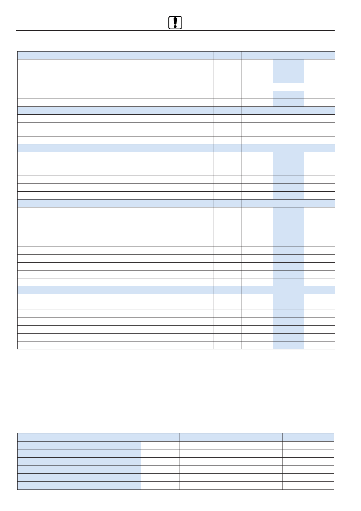
4.3 DATI TECNICI UNITÀ 4.3 UNIT TECHNICAL DATA
4 - CARATTERISTICHE TECNICHE 4 - TECHNICAL SPECIFICATIONS
Modello / Model D1500 D2300 D3100
Geometria / Geometry 2522 2522 2522
N° ranghi / Rows 333
N° circuiti (kit UTA) / Circuits number (AHU kit) 111
Ø in (liq) SAE-FLARE (3/8”) (ø 9,52 mm) (3/8”) (ø 9,52 mm) (3/8”) (ø 9,52 mm)
Ø out (gas) SAE-FLARE (5/8”) (ø 15,88 mm) (5/8”) (ø 15,88 mm) (5/8”) (ø 15,88 mm)
Volume [ltr] 1.8 2.2 2.9
Caratteristiche della batteria ad espansione diretta Features DX coil
pag. 8
MODELLO / MODEL D1500 D2300 D3100
Portata aria nominale / Nominal air flow m3/h 1500 2300 3100
Pressione statica utile nominale / Nominal external static pressure Pa 190 210 190
Pressione statica utile massima / Maximum external static pressure Pa 520 425 370
Alimentazione elettrica / Electrical power supply V/ph/Hz 230 / 1 / 50-60
Potenza assorbita massima totale / Total full load power input kW 2.12 2.12 2.35
Corrente assorbita massima totale / Total full load amperage A9.0 9.0 10.0
LIMITI OPERATIVI / WORKING LIMITS
Condizioni di temperatura - umidità limite esterne / Outdoor temperature - humidity working limits °C / % -5 … +45 °C / 5 … 95%
Condizioni di temperatura - umidità limite esterne con accessorio PRE-DX
Outdoor temperature - humidity working limits with PRE-DX option °C / % -15 … +45 °C / 5 … 95%
Condizioni di temperatura - umidità limite interne / Indoor temperature - humidity working limits °C / % +10 … +35 °C / 10 … 90%
VENTILATORI / FANS D1500 D2300 D3100
Tipologia motore / Motor typology EC EC EC
N° velocità / Number of speeds (1) 333
Controllo ventilazione / Fan control (1) Man Man Man
Potenza assorbita nominale totale / Total nominal power input kW 0.62 1.31 1.50
Corrente assorbita nominale totale / Total nominal load amperage A2.7 5.6 6.4
Efficienza statica dei ventilatori secondo (UE) n.327/2011 / Static efficiency of fans % 53.20% 55.90% 59.80%
RECUPERATORE DI CALORE / HEAT EXCHANGER D1500 D2300 D3100
Efficienza termica invernale / Winter thermal effic. (3) % 73.0% 73.2% 71.4%
Efficienza entalpica invernale / Winter enthalpy effic. (3) % 62.5% 62.7% 55.5%
Potenza termica totale recuperata / Total heating recovery capacity (3) kW 9.03 13.88 18.25
Temperatura aria mandata / Supply air temperature (3) °C 13.3 13.3 12.9
Efficienza termica estiva / Summer thermal effic. (4) % 60.1% 60.2% 57.4%
Efficienza entalpica estiva / Summer enthalpy effic. (4) % 58.3% 58.5% 52.5%
Potenza frigorifera totale recuperata / Total cooling recovery capacity (4) kW 1.81 2.79 3.58
Temperatura aria mandata / Supply air temperature (4) °C 28.4 28.4 28.6
Efficienza termica a secco / Dry thermal efficiency (5) % 73.1% 73.2% 73.0%
Livello di pressione sonora irradiato dall'involucro / Sound pressure level (LpA) (2) dB(A) 53 59 58
BATTERIA ESPANSIONE DIRETTA / DX COIL D1500 D2300 D3100
Potenza termica / Heating capacity (6) kW 8,6 (9,3) 12,2 (13,2) 17,1 (18,5)
Temperatura indicativa aria mandata / Approximate supply air temperature °C 30,0 (29,5) 29,0 (28,0) 29 (28,2)
Umidità indicativa aria mandata / Approximate supply air humidity %14 (14) 15 (15) 15 (15)
Potenza frigorifera totale / Total cooling capacity (7) kW 9.90 14.20 19.30
Potenza frigorifera sensibile / Sensible cooling capacity kW 6.70 9.90 13.40
Temperatura indicativa aria mandata / Approximate supply air temperature °C 15.1 15.7 15.6
Umidità indicativa aria mandata / Approximate supply air humidity %91 90 90

ORIENTAMENTO TIPO 01 / CONFIGURATION TYPE 01
L’orientamento raffigurato è relativo alla macchina vista dall’alto / The unit configuration is referred to the top view
pag. 9
4 - CARATTERISTICHE TECNICHE 4 - TECHNICAL SPECIFICATIONS
Lato destro / Right side
Aria espulsa / Exhaust air
Aria di rinnovo / Fresh air
fig. 1
4.4 ORIENTAMENTO UNITÀ (FIG.1) 4.4 IMOT CONFIGURATION (FIG.1)

Free cooling
Serranda Aperta / Damper Opened
Serranda chiusa / Damper closed
Disposizione tipica per Free Cooling
Free Cooling typical configuration
Aria espulsa / Exhaust air
Aria di rinnovo / Fresh air
4.5 FUNZIONALITÀ PRINCIPALI
Dispositivo by pass per free cooling / heating (fig. 2)
Le Unità sono provviste di sezione apposita interna di bypass parziale
del recuperatore.
Quando la temperatura esterna è prossima alla temperatura interna si
può ridurre sensibilmente lo scambio di calore attraverso il recupera-
tore. La macchina viene fornita con sistema di apertura con servomo-
tore gestito automaticamente.
4 - CARATTERISTICHE TECNICHE 4 - TECHNICAL SPECIFICATIONS
fig. 2
4.5 MAIN LOGIC CONTROL
Bypass device for free cooling / heating (fig. 2)
Units are equipped with special internal section for the bypass function.
When the air intake temperature is near the air outlet temperature the
heat recovery unit can be partly bypassed reducing the heat exchange.
The unit is equipped with electric actuator automatically managed.
Accessorio BER-PRE
Lato ispezione filtri
Mandata aria
Ripresa aria
Espulsione aria
Rinnovo aria
Accessorio BIOX
fig. 3
Accessorio BIOX-DX
Option BIOX-DX
Accessorio PRE-DX
Option PRE-DX
pag. 10
4 - CARATTERISTICHE TECNICHE 4 - TECHNICAL SPECIFICATIONS
K
Løs
B
A
øGAS
øLIQ
J
E
D1
G
F1F
D
C
W
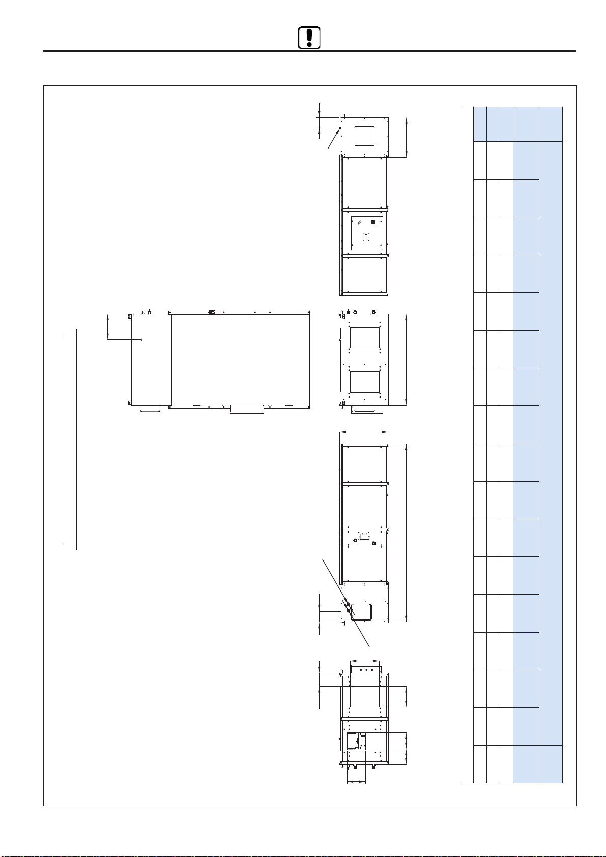
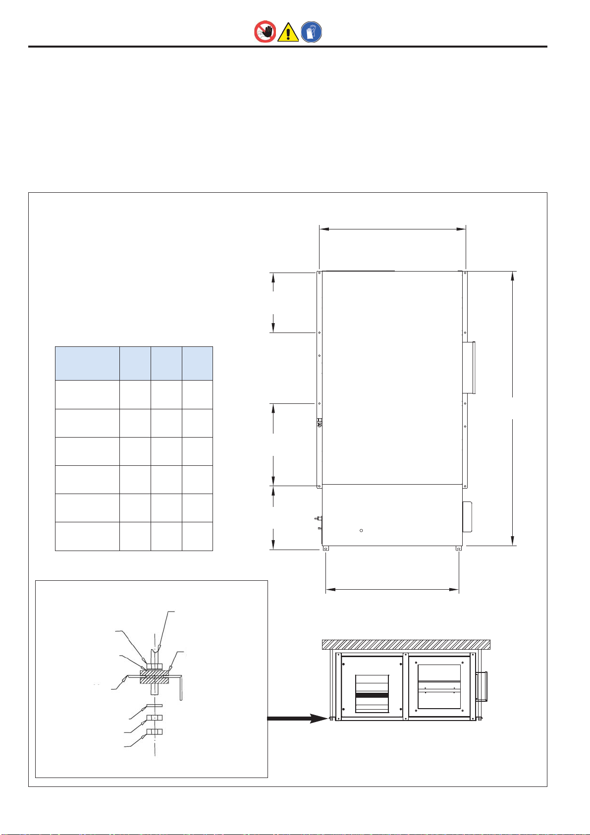
4.6 DIMENSIONI E PESI 4.6 DIMENSIONS AND WEIGHTS
Disegno dimensionale riferito all’orientamento
Dimensional drawing referred to orientation
fig. 4
pag. 11
Dimensione / Dimension Peso /
Weight
Modello
Model
A
[mm]
B
[mm]
C
[mm]
D
[mm]
D1
[mm]
E
[mm]
F
[mm]
F1
[mm]
G
[mm]
LIQ. (in)
Ø mm
GAS (out)
Ø mm
L
[mm]
S (1)
Ø inch
K
[mm]
J
[mm]
W
[mm] [Kg]
D1500 2535 670 1290 300 185 410 230 220 260 12 28 150 1/2" 570 160 360 230
D2300 2535 670 1290 500 185 410 330 220 290 16 28 150 1/2" 570 160 360 250
D3100 2635 670 1400 400 160 510 330 195 285 22 28 150 1/2" 570 160 360 270
(1) Scarico condensa / Condensate drain

4 - CARATTERISTICHE TECNICHE 4 - TECHNICAL SPECIFICATIONS
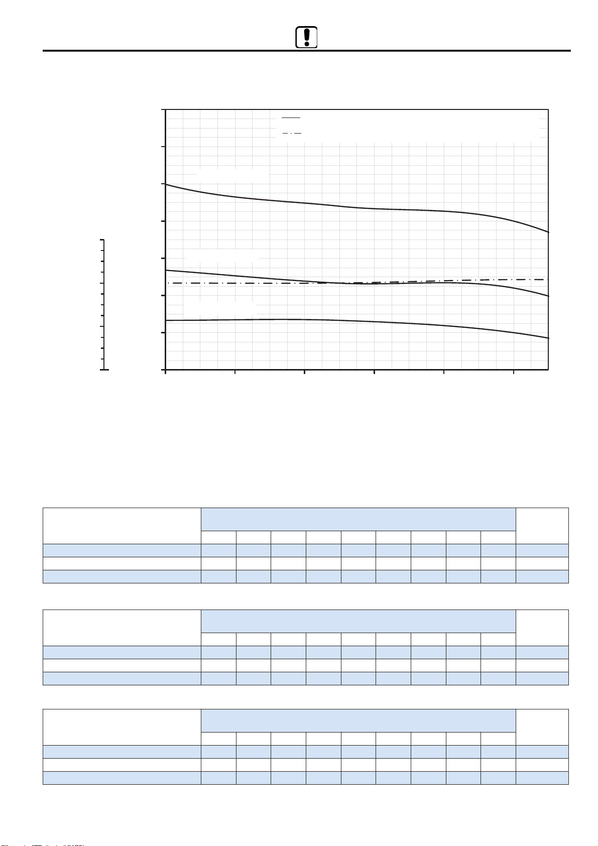
4.7 CURVE CARATTERISTICHE 4.7 CHARACTERISTIC CURVES
0
100
200
300
400
500
600
700
900 1000110012001300140015001600
4,0
5,0
6,0
7,0
Corrente assorbita max - Max absorbed current [A]
Pressione statica utile - External static pressure [Pa]
Portata aria - Air flow
[
m3/h
]
2000 rpm max
Pressione statica utile / External static pressure
Corrente assorbita max / Max absorbed current
1700 rpm
1380 rpm
D1500
0
100
200
300
400
500
600
700
800
900
1300 1400 1500 1600 1700 1800 1900 2000 2100 2200 2300
7,0
8,0
9,0
10,0
Corrente assorbita max - Max absorbed current [A]
Pressione statica utile - External static pressure [Pa]
Portata aria - Air flow
[
m3/h
]
2000 rpm max
Pressione statica utile / External static pressure
Corrente assorbita max / Max absorbed current
1700 rpm
1200 rpm
D2300
pag. 12
4 - CARATTERISTICHE TECNICHE 4 - TECHNICAL SPECIFICATIONS
0
100
200
300
400
500
600
700
2000 2200 2400 2600 2800 3000
7,0
8,0
9,0
10,0
Corrente assorbita max - Max absorbed current [A]
Pressione statica utile - External static pressure [Pa]
Portata aria - Air flow
[
m3/h
]
2000 rpm max
Pressione statica utile / External static pressure
Corrente assorbita max / Max absorbed current
1400 rpm
1200 rpm
D3100
D1500
Potenza sonora Lw per frequenza di centro banda
Sound power levels Lw at center band frequencies Lw globale
Total Lw
Hz 63 125 250 500 1000 2000 4000 8000
Canale di mandata / Supply duct dB(A) 33.8 58.9 68.4 65.8 69.0 67.2 62.0 53.9 74.2
Canale di espulsione / Exhaust duct dB(A) 33.8 59.9 68.4 65.8 69.0 67.2 62.0 53.9 74.3
Esterno involucro / Outside the casing dB(A) 28.8 48.1 56.6 51.5 54.4 52.4 30.7 17.1 60.5
D2300
Potenza sonora Lw per frequenza di centro banda
Sound power levels Lw at center band frequencies Lw globale
Total Lw
Hz 63 125 250 500 1000 2000 4000 8000
Canale di mandata / Supply duct dB(A) 44.8 66.9 77.4 68.8 70.0 69.2 70.0 58.9 79.8
Canale di espulsione / Exhaust duct dB(A) 44.8 66.9 77.4 68.8 70.0 69.2 70.0 58.9 79.8
Esterno involucro / Outside the casing dB(A) 39.8 55.6 65.6 54.5 55.4 54.4 38.7 22.1 66.9
D3100
Potenza sonora Lw per frequenza di centro banda
Sound power levels Lw at center band frequencies Lw globale
Total Lw
Hz 63 125 250 500 1000 2000 4000 8000
Canale di mandata / Supply duct dB(A) 35.8 66.9 76.4 67.8 70.0 69.2 67.0 57.9 79.0
Canale di espulsione / Exhaust duct dB(A) 35.8 66.9 76.4 67.8 70.0 69.2 67.0 57.9 79.0
Esterno involucro / Outside the casing dB(A) 30.8 55.6 64.6 53.5 55.4 54.4 35.7 21.1 66.1
4.8 LIVELLI DI RUMOROSITÀ SONORA 4.8 SOUND POWER LEVELS
pag. 13
4 - CARATTERISTICHE TECNICHE 4 - TECHNICAL SPECIFICATIONS
4.9 ACCESSORI
4.9.1 Resistenza elettrica di pre-riscaldamento - PRE-DX
Le resistenze, complete di termostati di sicurezza e di relè di comando,
sono del tipo a filamento per contenere le perdite di carico.
La resistenza PRE-DX è installata all’interno della macchina sulla presa
aria esterna, a valle del filtro ed effettua un pre-riscaldamento dell’aria
quando la temperatura è inferiore ad un set impostabile (-5°C default).
Questo consente di massimizzare il rendimento igrometrico del recu-
peratore evitando la formazione di ghiaccio in espulsione.
Le caratteristiche tecniche sono indicate nella tabella seguente.
4.9 OPTIONS
4.9.1 PRE and post-heating electric coil - PRE-DX
The electric heater contains a filament-type element, which limits pres-
sure drop. Safety thermostats and control relay are included.
The PRE-DX pre-heater is installed inside the unit in fresh air stream ,
after the filter and performs a pre-heating of the outdoor air when the
fresh air temperature is less than a sattable value (default -5°C). This
arrangement ensures the maximum humidity efficiency, avoiding frost
on the exhaust air stream.
The technical characteristics are shown in the following table.
PRE RISCALDAMENTO ELETTRICO / ELECTRIC PRE HEATING SECTION PRE-DX D1500 D2300 D3100
Potenza nominale / Nominal capacity kW 6.0 6.0 12.0
Tensione / Voltage V 400 400 400
Fasi / Phases n° 3 3 3
Stadi / Steps n° 1 1 1
Corrente assorbita / Current A 8.7 8.7 17.3
Differenza temperatura aria ingresso-uscita / Air Delta T input-output °C 12.0 9.0 11.2
Peso / Weight kg 2.5 2.5 5.0
4.9.2 Sistema di sanificazione - BIOX-DX
La tecnologia del sistema BIOX-DX è costituita da uno speciale conden-
satore formato da un cilindro realizzato in quarzo e da speciali maglie me-
talliche e viene alimentato con una tensione alternata monofase, a basso
consumo energetico. Il campo elettrico generato tra le particolari armature
del condensatore, dà luogo alla “liberazione” di piccoli ioni di ossigeno ne-
gativi e di ioni positivi che si aggregano facilmente sotto forma di “cluster”
o ioni molecolari, dotati di elevato potere ossidante.
L’utilizzo costante del dispositivo BIOX-DX garantisce un notevole miglio-
ramento della qualità dell’ aria negli ambienti indoor in termini di: compo-
sizione chimica, attività batterica, equilibrio elettrostatico, assenza di polveri
sottili e odori sgradevoli, con conseguenze positive negli ambienti e sulla
salute e il benessere delle persone.
Benefici per le persone:
• riduzione dei rischi di contagio dovuti alla proliferazione dei batteri
• miglioramento delle funzioni e riduzione delle malattie respiratorie
• riduzione degli stati d’ ansia, stress, sonnolenza e insofferenza
all’ambiente.
Benefici per gli ambienti:
• eliminazione delle muffe che intaccano le superfici di soffitti, pareti
e angoli poco ventilati
• eliminazione degli odori senza l’ utilizzo di prodotti chimici dannosi
per la salute.
• clusterizzazione delle polveri sospese e riduzione drastica degli acari
• eliminazione delle cariche elettrostatiche.
Con il sistema BIOX-DX l’aria all’interno degli ambienti è costantemente
sanificata e deodorizzata come richiesto dalla normativa comunitaria vi-
gente in materia di sicurezza e salute.
Il sistema è installato dentro la macchina, a monte del ventilatore di man-
data (vedere fig. 3). Esso entra in funzione all’accensione dei ventilatori;
l’assorbimento elettrico massimo è 40W.
4.9.2 Purifying system - BIOX-DX
The BIOX-DX technology is constituted by a special condenser made by
a cylinder of quartz and by special metallic net and it is feeded by a mo-
nophase alternate tension, low power consumption.
The electric field generated among the particular plate of the condenser,
gives place to the “liberation” of little negative ions of oxigen and of positive
ions, which easily unit as “cluster” or molecular ions, characterized by ele-
vated oxidizing power.
The constant use of the BIOX-DX device guarantees a considerable im-
provement of the quality of the air in indoor places, like this: chemical com-
position, bacterial activity, electrostatic balance, assence of fine dusts and
unpleasant smells, with positive consequences in rooms for the health and
the well-being of people.
Benefits for people:
• reduction of infection risks caused by bacterial proliferation
• improvement of the function and reduction of the dis eases of
the respiratory system
• reduction of anxiety, stress, sleepiness and intolerance of rooms.
Benefits for rooms:
• elimination of moulds which damage ceilings, walls and corners
not much aired
• elimination of smells without the use of chemical products dangerous
for health
• drastic reduction of mites
• elimination of electrostatic charge
With the BIOX-DX system , the indoor air is constantly healthy and deo-
dorized as required by EEC regulation in force concerning safety and he-
alth.
The system is installed inside the unit, before the supply fan (see picture
3). It starts to work when fans are switched on; the maximum power con-
sumption is 40W.
pag. 14
• Le unità trattamento aria e i loro accessori sono inseriti in scatole di
cartone che dovranno rimanere integre fino al momento del mon-
taggio.
• I componenti che, per esigenze tecniche, costruttive, di trasporto o
qualsivoglia, non vengono montati a bordo macchina, ma spediti se-
paratamente all’interno dell’unità o meno, vengono protetti con ade-
guati involucri e debitamente menzionati sulla bolla di
accompagnamento delle merci.
• Si diffida dal sovrapporre qualsiasi altro materiale sulla merce: la
ditta costruttrice declina ogni responsabilità in caso di danni derivanti
da tale carico.
6 - SCARICO 6 - UNLOADING
6.1 CONTROLLO AL RICEVIMENTO
Si consiglia che al ricevimento della merce, prima dello scarico, sia ef-
fettuato un controllo su tutto il materiale in consegna al fine di verificare
l’esistenza di eventuali danni causati dal trasporto. Gli eventuali danni
devono essere debitamente comunicati al vettore e specificati nella
clausola di riserva riportata nella bolla di accompagnamento.
6.2 SOLLEVAMENTO E MOVIMENTAZIONE
E’ vivamente consigliato:
• Il peso di ogni singola macchina è riportato sul presente manuale.
• Evitare rotazioni senza controllo.
• Appoggiare con prudenza la merce in modo da evitarne bruschi spo-
stamenti o, peggio, cadute.
6.3 STOCCAGGIO
In caso di stoccaggio prolungato prima dell’installazione, le macchine
dovranno essere protette dalla polvere, dalle intemperie e tenute lon-
tane da fonti di calore e vibrazioni.
IL FISSAGGIO DEL CARICO SUL CAMION È A CARICO DEL TRA-
SPORTATORE È DEVE ESSERE ESEGUITO, CON CORDE O CIN-
GHIE, IN MANIERA DA NON DANNEGGIARE L’INVOLUCRO.
THE FASTENING OF THE LOAD ON THE TRUCK IS THE RESPONSI-
BILITY OF THE CARRIER, AND MUST BE PERFORMED, USING
STRAPS OR ROPES, SO AS TO AVOID DAMAGING THE PACKAGING
PER LA MOVIMENTAZIONE UTILIZZARE, IN FUNZIONE DEL PESO,
MEZZI ADEGUATI.
WHEN HANDLING THE UNITS, USE SUITABLE MEANS ACCORDING
THE WEIGHTS INVOLVED.
LA DITTA COSTRUTTRICE DECLINA OGNI RESPONSABILITÀ PER
DANNEGGIAMENTI DELLA MERCE DOVUTI AD UNO SCARICO NON
CORRETTO O A NON ADEGUATA PROTEZIONE DALLE INTEMPERIE
THE MANUFACTURER DECLINES ALL LIABILITY FOR DAMAGE DE-
RIVING FROM INCORRECT UNLOADING OR INADEQUATE PROTEC-
TION OF THE UNITS AGAINST THE ELEMENTS.
5- TRASPORTO 5- TRANSPORT
• The air handling units are packed in cardboard boxes that must re-
main intact until assembly.
• The components that, due to technical, constructional, transport or
other requirements are not fitted on the unit, but sent separately ei-
ther inside the unit or otherwise, are specially protected and duly
described on the packing list.
• No other material must be stacked on the products: the manufacturer
declines all liability in the event of damage deriving from such loads.
6.1 CHECKS UPON RECEIPT
When receiving the goods, before unloading, all the material delivered
must be checked to ascertain the presence of any damage caused du-
ring transport. Any damage found must be reported to the carrier, ac-
cepting the goods with reservation and specifying the type of damage
on the delivery documents.
6.2 HOISTING AND HANDLING
It is strongly recommended :
• The weight of the units is shown on this manual.
• Avoid uncontrolled rotations.
• Place the goods down with care, avoiding sudden movements or,
worse, dropping the goods.
6.3 STORAGE
In the event of extended storage before installation, keep the units pro-
tected from dust and bad weather and away from sources of vibrations
and heat.
pag. 15

7.1 DEFINIZIONI
UTENTE - L'utente è la persona, l'ente o la società, che ha acquistato
o affittato la macchina e che intende usarla per gli scopi concepiti.
UTILIZZATORE / OPERATORE - L'utilizzatore o operatore, è la per-
sona fisica che è stata autorizzata dall'utente a operare con la mac-
china.
PERSONALE SPECIALIZZATO - Come tali, si intendono quelle per-
sone fisiche che hanno conseguito uno studio specifico e che sono
quindi in grado di riconoscere i pericoli derivati dall'utilizzo di questa
macchina e possono essere in grado di evitarli.
• Nelle operazioni di installazione, usare un abbigliamento idoneo e
antinfortunistico, ad esempio: occhiali, guanti, ecc. come indicato
dalle normative vigenti.
• Durante l'installazione operare in assoluta sicurezza, ambiente pulito
e libero da impedimenti.
• Rispettare le leggi in vigore nel Paese in cui viene installata la mac-
china, relativamente all'uso e allo smaltimento dell'imballo e dei pro-
dotti impiegati per la pulizia e la manutenzione della macchina,
nonché osservare quanto raccomanda il produttore di tali prodotti.
• Prima di mettere in funzione l'unità controllare la perfetta integrità
dei vari componenti e dell'intero impianto.
• Evitare assolutamente di toccare le parti in movimento o di interporsi
tra le stesse.
• Non procedere con i lavori di manutenzione e di pulizia, se prima
non è stata disinserita la linea elettrica.
• La manutenzione e la sostituzione delle parti danneggiate o usurate
deve essere effettuata solamente da personale specializzato ese-
guendo le indicazioni riportate in questo manuale.
• Le parti di ricambio devono corrispondere alle esigenze definite dal
Costruttore.
• In caso di smantellamento dell’unità, attenersi alle normative antin-
quinamento previste.
N.B. L'installatore e l'utilizzatore nell'uso dell’unità devono tenere
conto e porre rimedio a tutti gli altri tipi di rischio connessi con
l'impianto. Ad esempio rischi derivanti da ingresso di corpi estra-
nei, oppure rischi dovuti al convogliamento di gas pericolosi in-
fiammabili o tossici ad alta temperatura.
LA DITTA COSTRUTTRICE DECLINA QUALSIASI RESPONSABILITÀ
PER LA MANCATA OSSERVANZA DELLE NORME DI SICUREZZA E
DI PREVENZIONE DI SEGUITO DESCRITTE. DECLINA INOLTRE OGNI
RESPONSABILITÀ PER DANNI CAUSATI DA UN USO IMPROPRIO
DELL’UNITÀ E/O DA MODIFICHE ESEGUITE SENZA AUTORIZZA-
ZIONE.
THE MANUFACTURER DECLINES ALL RESPONSIBILITY FOR THE
FAILURE TO COMPLY WITH THE SAFETY AND ACCIDENT-PREVEN-
TION STANDARDS DESCRIBED BELOW.
IT ALSO DECLINES ALL LIABILITY FOR DAMAGE CAUSED BY IM-
PROPER USE OF THE UNIT AND/OR MODIFICATIONS PERFORMED
WITHOUT AUTHORISATION.
L'INSTALLAZIONE DEVE ESSERE EFFETTUATA DA PERSONALE
SPECIALIZZATO. SPECIALISED STAFF MUST PERFORM INSTALLATION.
7.2 NORME DI SICUREZZA 7.2 SAFETY STANDARDS
7.1 DEFINITIONS
CUSTOMER - The customer is the person, the agency or the company
who bought or rented the unit
USER / OPERATOR - The operator or user is the physical person who
uses the unit for the purpose for which it was designed
SPECIALISTIC STAFF - It is composed by the physical trained per-
sons, able to recognize any danger due to the proper and improper
use of the unit and able to avoid or repair it inflammable or toxic gases
at a high temperature.
• Wear suitable and accident-prevention clothing during installation,
for example: goggles, gloves etc. as indicated in the current regula-
tion
• During installation operate in complete safety, clean environment
and free from obstructions.
• Respect the laws in force, in the country in which the machine is in-
stalled, relative to use and disposal of packaging and the products
used for cleaning and maintenance of the machine, as well as com-
plying with that recommended by the producer of these products.
• Before starting the unit, check the perfect integrity of the various
components of the entire plant.
• Do not touch moving parts or intervene between these.
• Do not perform maintenance and cleaning until the electric line has
been connected.
• The maintenance and replacement of damaged or worn parts must
only be performed by specialised staff and following the indications
given in this manual.
• The spare parts must correspond to the requirements defined by the
Manufacturer.
• If the unit must be dismantled, follow the envisioned anti-pollution
standards.
N.B. When using the unit, the installer and user must consider
and solve all risks connected to theplant. For example, risks de-
riving from the entry of foreign bodies or risks due to the conve-
ying of dangerous inflammable or toxic gases at a high
temperature.
7 - INSTALLAZIONE E MESSA IN SERVIZIO 7 - INSTALLATION AND START UP
pag. 16

7 - INSTALLAZIONE E MESSA IN SERVIZIO 7 - INSTALLATION AND START UP
min 600 A
B
Estrazione recuperatore
Heat recovery extraction
Modello
Model A (mm) B (mm)
D1500 550 450
D2300 650 500
D3100 700 550
7.3 INFORMAZIONI PRELIMINARI
• Operare rispettando le norme di sicurezza in vigore, accertandosi
della sufficiente libertà di movimento e della pulizia degli ambienti di
installazione
• Usare idoneo abbigliamento antinfortunistico e dispositivi individuali
di protezione (occhiali, guanti, ecc.).
• Trasportare la sezione imballata il più possibile vicino al luogo di in-
stallazione.
• Non sovrapporre attrezzi o pesi sull'unità imballata.
• Non usare l'unità come deposito per attrezzi di cantiere.
• Evitare di toccare le parti mobili e di usare le stesse come punti di
sollevamento/movimentazione.
• Verificare la perfetta integrità dei vari componenti dell'unità.
7.4 LUOGO D'INSTALLAZIONE
• Verificare che il piano di appoggio o di sostegno sia in grado di sop-
portare il peso della(e) macchina(e) e tale da non causare vibrazioni.
• Verificare che il piano di appoggio o di sostegno sia perfettamente
orizzontale onde permettere il corretto accoppiamento delle varie se-
zioni.
• Non posizionare l’unità in locali in cui siano presenti gas infiammabili,
sostanze acide, aggressive e corrosive che possono danneggiare i
vari componenti in maniera irreparabile.
• Prevedere spazi tecnici adeguati tali da garantire le operazioni di in-
stallazione nonché di manutenzione e di sostituzione dei componenti
quali batterie, filtri ecc. (fig. 5).
• Nell’eventualità che la macchina debba essere installata sospesa bi-
sogna prevedere un sistema di aggancio a soffitto per ciascuna delle
sezioni che compongono l’unità di trattamento.
7.3 PRELIMINARY INFORMATION
• Work while meeting the current safety regulations, ensuring sufficient
space to move and the cleanliness of jobsite.
• Wear protective clothing and personal protective equipment (glasses,
gloves, etc.).
• Move the packed section as close as possible to the place of instal-
lation.
• Don't place tools or other jobsite equipment over the packed unit.
• Don't use the unit as a store of yard tools.
• Don't touch moving parts and don't use them as supports.
• Check the full integrity of all unit components.
7.4 INSTALLATION LOCATION
• Make sure that the support surface is able to support the weight of
the unit(units) and will not cause vibrations.
• Make sure that the support surface is perfectly horizontal so as to
Allow the correct coupling of the various sections.
• Never position the unit in rooms where there are flammable gases
or acidic, aggressive or corrosive substances that may irreparably
damage the various components.
• Leave a minimum amount of free space around the unit, as shown
in the figure, so as to allow for installation, maintenance and the re-
placement of components, such as coils, filters etc. (fig. 5).
• If the unit is hung from the ceiling all the sections that make up the
air handling unit must be connected to the ceiling.
fig. 5
pag. 17
E
D
A
C
C1
B
7 - INSTALLAZIONE E MESSA IN SERVIZIO 7 - INSTALLATION AND START UP
7.5 POSIZIONAMENTO DELLA MACCHINA
Qui di seguito sono illustrate alcune sequenze del montaggio:
1. Eseguire la foratura a soffitto e fissare i tiranti filettati M8 come indi-
cato in figura.
2. Posizionare l'unità sui tiranti, posizionando gli antivibranti in gomma
in dotazione (fig. 6).
3. Bloccare l'unità serrando i bulloni di fissaggio.
7.5 POSITIONING OF THE MACHINE
Some assembly sequences are illustrated below:
1. Drill the ceiling and fix M8 threaded tie-rods, as indicated in the fi-
gure.
2. Position the unit on the tie-rods with the rubber antivibrating supplied
(fig. 6).
3. Block the unit by fastening the fixing bolt.
fig. 6
dado / nut
rondella / washer
staffa / bracket
tirante
threaded rod
antivibrante
anti-vibrating
Modello /
Model D1500 D2300 D3100
A (mm) 1965 1965 2065
B (mm) 1345 1345 1450
C (mm) 550 550 550
C1 (mm) 760 760 760
D (mm) 570 570 570
E (mm) 1225 1225 1335
rondella / washer
dado / nut
dado / nut
pag. 18

Ispezione Batteria
Battery inspection
Gas
Gas
Liquido
Liquid
Batteria ad espansione diretta
Direct expansion coil
Lato quadro elettrico
Electric board side
Kit UTA (se richiesto dal cliente)
Kit UTA (if required by the customer)
Connessioni frogorifere
Refrigerant connections
7 - INSTALLAZIONE E MESSA IN SERVIZIO 7 - INSTALLATION AND START UP
7.6 CONNECTION TO THE DUCTS
• The ducts must be dimensioned depending on the plant and the ae-
raulic features of the unit fans. An incorrect calculation of the ducting
causes a loss of power or the intervention of any devices present on
the plant.
• It is recommended to use insulated ducts to prevent the formation of
condensate and attenuate the noise level.
• To prevent transmission of any machine vibrations into the environ-
ment it is recommended top lace an anti-vibration joint between the
fan vents and the ducts. The electrical continuity must however be
guaranteed between the duct and the machine via the earth cable.
7.7 HYDRAULIC CONNECTIONS
• The installation and connection operations of the hydraulic pipes are
operations that can compromise the good functioning of the plant or
worse, cause irreversible damage to the machine.
These operations must only be performed by specialised staff.
• The units are all equipped with condensate drip tray made of galva-
nized metal sheet.
• The condensate drip tray has a drain with G 1/2 male.
• The drain system must have a suitable siphon for preventing the un-
desired entry of air into the depressurised systems or the undesired
exit of air in pressurised systems. Otherwise the condensate does
not drain and it would wet the inside of the unit with unwanted
consequences.This siphon is also useful to prevent the infiltration
of odours or insects.
• The dimensioning of the siphons in the case of depressurised tray,
must be done according to the following (fig. 7) and table.
fig. 7
7.6 COLLEGAMENTO AI CANALI
• I canali devono essere dimensionati a funzione dell’impianto e delle
caratteristiche aerauliche dei ventilatori dell’unità. Un errato calcolo
delle canalizzazioni causa perdite di potenza o l’intervento di even-
tuali dispositivi presenti sull’impianto.
• Per prevenire la formazione di condensa ed attenuare il livello di ru-
morosità si consiglia di utilizzare canali coibentati.
• Per evitare di trasmettere le eventuali vibrazioni della macchina in
ambiente, è consigliato interporre un giunto antivibrante fra le bocche
ventilanti e i canali. Deve comunque essere garantita la continuità
elettrica fra canale e macchina tramite un cavo di terra.
7.7 COLLEGAMENTI IDRAULICI SCARICHI CONDENSA
• Le operazioni di installazione e collegamento delle tubazioni idrauli-
che sono operazioni che possono compromettere il buon funziona-
mento dell'impianto o, peggio, causare danni irreversibili alla
macchina.
Queste operazioni sono da effettuarsi solo da personale spe-
cializzato.
• Le unità sono tutte dotate di vasca raccogli condensa in lamiera zin-
cata.
• La vasca di raccolta condensa è provvista di raccordo di scarico G
1/2” maschio.
• Il sistema di scarico deve prevedere un adeguato sifone per impedire
l'entrata d'aria nei sistemi in depressione o l’uscita d'aria nei sistemi
in pressione. In caso contrario la condensa non si scarica e si
bagnerebbe l’interno della macchina con conseguenze indesi-
derate. Tale sifone risulta inoltre utile per evitare l'infiltrarsi di odori
o insetti.
• Il dimensionamento e l'esecuzione dei sifoni, nel caso di vasca in
depressione deve essere eseguito secondo la figura (fig. 7) e la ta-
bella seguenti.
Modello / Model H [mm]
D1500 80
D2300 80
D3100 80
Livello vasca condensa
Drip tray level
IMPORTANTE: SI FA DIVIETO DI METTERE IN FUNZIONE
L'UNITÀ SE LE BOCCHE DEI VENTILATORI NON SONO CANA-
LIZZATE O PROTETTE CON RETE ANTINFORTUNISTICA SE-
CONDO LE NORMATIVE VIGENTI.
IMPORTANT: IT IS PROHIBITED TO START THE UNIT IF THE
FAN VENTS ARE NOT DUCTED OR PROTECTED WITH ACCI-
DENT-PREVENTION MESH ACCORDING TO THE CURRENT RE-
GULATION.
pag. 19
This manual suits for next models
2
Table of contents


