TSL LTA-X48M User manual
IP camera tester
User Manual
(V01.00)

Thank you for purchasing the IP camera tester. Please read the manual before using the IP
camera tester and use properly.
For using the IP camera tester safely, please first read the「Safety Information」carefully in the
manual.
The manual should be kept well in case of reference.
Keep the S/N label for after-sale service within warranty period. Product without S/N label will
be charged for repair service.
If there is any question or problem while using the IP camera tester, or damages occurred on the
product, please contact our technical Department.

Content
1 .Safety information-----------------------------------------------------------------------------------------------------------1
2. IP Camera Tester Introduction -------------------------------------------------------------------------------------------2
2.1 General-----------------------------------------------------------------------------------------------------------------2
2.2 Packing list-------------------------------------------------------------------------------------------------------------3
2.3 Function interface ---------------------------------------------------------------------------------------------------4
3. Operation ----------------------------------------------------------------------------------------------------------------------7
3.1 Installing the Battery------------------------------------------------------------------------------------------------7
3.2 Instrument connection---------------------------------------------------------------------------------------------8
3.2.1 IP camera connection --------------------------------------------------------------------------------------------8
3.2.2 Analog camera connection ----------------------------------------------------------------------------------- 10
3.2.3 HD Coaxial camera connection------------------------------------------------------------------------ 11
3.2.4 HDMI IN----------------------------------------------------------------------------------------------------- 12
3.3 OSD menu ----------------------------------------------------------------------------------------------------------- 12
3.3.1 Lite mode & Normal mode----------------------------------------------------------------------------- 12
3.3.2 Drop-down Menu ---------------------------------------------------------------------------------------- 16
3.3.3 Short cut-menu ------------------------------------------------------------------------------------------- 17
3.3.4 Screen capture -------------------------------------------------------------------------------------------- 18
3.3.5 TesterPlay -------------------------------------------------------------------------------------------------- 18
3.3.6 Rapid video------------------------------------------------------------------------------------------------- 20
3.3.7 IP discovery ------------------------------------------------------------------------------------------------ 21
3.3.8 Rapid ONVIF test------------------------------------------------------------------------------------------ 22
3.3.9 IP camera test --------------------------------------------------------------------------------------------- 35
3.3.10 HDMI IN --------------------------------------------------------------------------------------------------- 38
3.3.11 Video monitor test ------------------------------------------------------------------------------------- 42
3.3.12 Color-bar generator (TV OUT) ----------------------------------------------------------------------- 48
3.3.13 CVI camera test------------------------------------------------------------------------------------------ 49

3.3.14 TVI camera test------------------------------------------------------------------------------------------ 55
3.3.15 AHD camera test ---------------------------------------------------------------------------------------- 57
3.3.16 Network tool --------------------------------------------------------------------------------------------- 59
(1)IP address scan ------------------------------------------------------------------------------------------- 59
(2)PING Test -------------------------------------------------------------------------------------------------- 59
(3)Network test (Ethernet bandwidth test)----------------------------------------------------------- 60
(4)Port Flashing ---------------------------------------------------------------------------------------------- 63
(5)DHCP server----------------------------------------------------------------------------------------------- 64
(6)Trace route ------------------------------------------------------------------------------------------------ 64
(7)Link monitor----------------------------------------------------------------------------------------------- 65
3.3.17 Rapid IP Discovery -------------------------------------------------------------------------------------- 66
3.3.18 PoE power / DC12V 2A and DC 5V 2A USB power output ------------------------------------ 66
3.3.19 Cable Test------------------------------------------------------------------------------------------------- 68
3.3.20 RJ45 cable TDR test------------------------------------------------------------------------------------- 69
3.3.21 PoE voltage and power measurement ------------------------------------------------------------ 71
3.3.22 12V power input test ---------------------------------------------------------------------------------- 72
3.3.23 Audio Record--------------------------------------------------------------------------------------------- 73
3.3.24 Data monitor--------------------------------------------------------------------------------------------- 74
3.3.25 Audio player---------------------------------------------------------------------------------------------- 74
3.3.26 Media Player --------------------------------------------------------------------------------------------- 75
3.3.27 RTSP Player ----------------------------------------------------------------------------------------------- 75
3.3.28 NVMS7000------------------------------------------------------------------------------------------------ 77
3.3.29 Update----------------------------------------------------------------------------------------------------- 78
3.3.30 Office------------------------------------------------------------------------------------------------------- 78
3.3.31 LED Flashlight -------------------------------------------------------------------------------------------- 79
3.3.32 Browser---------------------------------------------------------------------------------------------------- 79
3.3.33 Notepad: -------------------------------------------------------------------------------------------------- 80
3.3.34 System Setting------------------------------------------------------------------------------------------- 81
3.3.35 File explorer ---------------------------------------------------------------------------------------------- 85

3.3.36 Theme ----------------------------------------------------------------------------------------------------- 87
3. 4 Audio test----------------------------------------------------------------------------------------------------------- 89
3.5 PoE power output ------------------------------------------------------------------------------------------------- 90
3.7 DC12V 2A power output----------------------------------------------------------------------------------------- 91
4. Specifications --------------------------------------------------------------------------------------------------------------- 93
4.1 General Specifications-------------------------------------------------------------------------------------------- 93

1
1 .Safety information
◆The tester is intended to use in compliance with the local rules of the electrical usage and avoid
applying at the places which are inapplicable for the use of electrics such as hospital, gas station etc.
◆To prevent the functional decline or failure, the product should not be sprinkled or damped.
◆The exposed part of the tester should not be touched by the dust and liquid.
◆During transportation and use, it is highly recommended to avoid the violent collision and vibration
of the tester, lest damaging components and causing failure.
◆Don’t leave the tester alone while charging and recharging. If the battery is found severely hot, the
tester should be powered off from the electric source at once. The tester should not be charged
over 8 hours.
◆Don’t use the tester where the humidity is high. Once the tester is damp, power off immediately
and move away other connected cables.
◆The tester should not be used in the environment with the flammable gas.
◆Do not disassemble the instrument since no component inside can be repaired by the user. If the
disassembly is necessary indeed, please contact with the technician of our company.
◆The instrument should not be used under the environment with strong electromagnetic
interference.
◆Don’t touch the tester with wet hands or waterish things.
◆Don’t use the detergent to clean and the dry cloth is suggested to use. If the dirt is not easy to
remove, the soft cloth with water or neutral detergent can be used. But the cloth should be
tweaked sufficiently.

2
2. IP Camera Tester Introduction
2.1 General
The 4.3 inch IPS touch screen IP camera monitor is designed for maintenance and installation of IP
cameras, analog cameras, TVI, CVI AHD, cameras, as well as testing 4K H.264 /4k H.265 camera by
mainstream, The 960x540 resolution enables it to display network HD cameras and analog cameras in
high resolution. The unit supports many ONVIF PTZ and analog PTZ control. The combination of touch
screen and key buttons make the IP camera tester very user- friendly.
The tester is also a great tool for Ethernet network testing. It can test PoE power voltage, PING, and IP
address searching. You can use the blue cable tracer to locate individual connected cables from a
bundle of cables. Test LAN cable for proper connection termination. Other functions include providing
24W PoE power to your camera, HDMI IN and out, CVBS loop test , testing IP and analog at the same
time, LED Flashlight, DC 12V 2A power output and much more. Its portability, user-friendly design and
many other functions make the IP tester an essential tool for all installers or technicians.

3
2.2 Packing list
1). Tester
2). Adaptor DC12V 2A
3) Network cable tester
4) Polymer lithium ion battery (7.4V DC 5000mAh)
5). BNC cable
6). RS485 cable
7). Output Power cable
8). Audio cable
9). Safety cord
10). Tool bag
11). Manual
12).8GB SD card
4
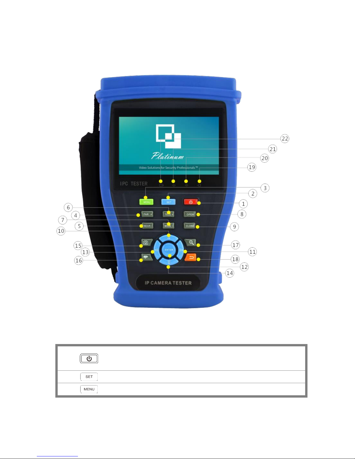
2.3 Function interface
1
Press more than 2 seconds, turn on or off the device, short press to turn on or off
the menu display
2
Set key
3
Menu key, press it to call shortcut- menu
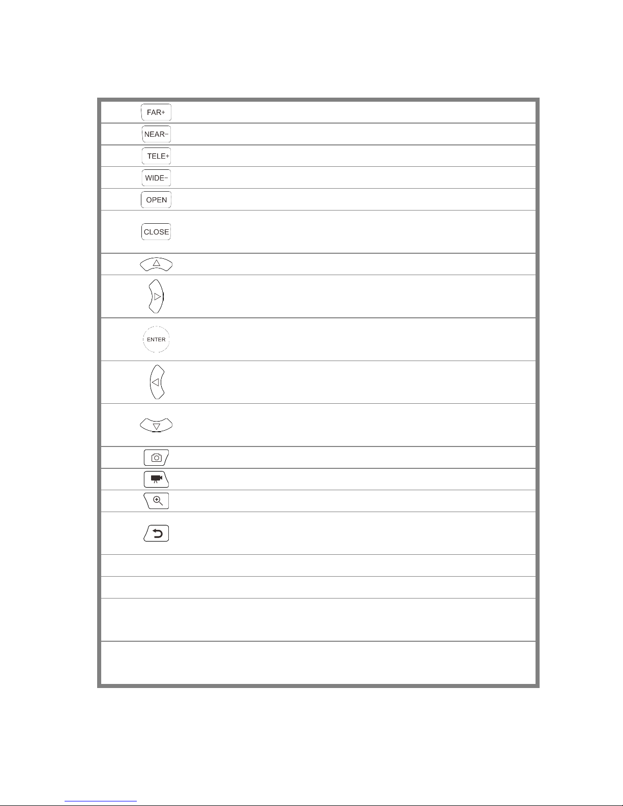
5
4
Near focus: Focus the image nearby
5
Far focus: Focus the image faraway
6
TELE: zoom in the image
7
WIDE: zoom out the image
8
Open/set, Confirm the setting of parameters, open or enlarge the aperture
9
Return/Close: Return or cancel while setting parameters of the menu, close or
decrease the aperture
10
Upward, set function or add parameter. Tilt the PTZ upward
11
Rightward, select the parameter whose value will be changed. Add the value of
the parameter. Pan the PTZ right
12
Confirm key (Long press it to capture screen interface)
13
Leftward, select the parameter whose value will be changed
14
Downward, set function or reduce the value of the parameter. Tilt the PTZ
downward
15
Snapshot
16
Video record
17
Open/set ,Confirm the setting of parameters, open or enlarge the aperture
18
Return/Close : Return or cancel while setting parameters of the menu, close or
decrease the aperture
19
The power indicator: it lights green while the tester is powered on by the adapter
20
The data accepted indicator: it lights red while the data is being received
21
The RS485/RS232 data transmission indicator: it lights red while the data is being
transmitted
22
The charge indicator: it lights red while the battery is being charged. As the
charging is complete, the indicator turns off automatically

6
Top interface
Left interface
Right interface
23
HDMI input
24
LED lamp
25
DC12V2A power output , for provisional DC power supply

7
26
RS485 Interface: RS485communication for the PTZ
27
RS232 Interface: RS232 communication for the PTZ"HD IN" , AHD /TVI/CVI Coaxial
interface
28
Video image signal output(BNC interface)/cable tracer interface (Optional)
29
Video image signal input(BNC interface)/ AHD,CVI and TVI input (BNC interface)
30
UTP cable port: UTP cable tester port/ Cable tracer port
31
Micro SD card moveable, comes with 8GB, supports up to 32GB
32
Audio input
33
HDMI output interface
34
Audio and earphone output
35
5V2A USB power output , as power bank
36
DC12V2A charging interface
37
PSE power sourcing equipment. Tests PoE voltage
38
PoE power supply output or LAN test port (Use to test PoE or non-PoE IP camera)
3. Operation
3.1 Installing the Battery
The tester has built-in lithium ion polymer rechargeable battery. The battery cable inside battery
cabin should be disconnected for safety during transportation!
Prior to the use of the instrument, the battery cables inside the battery cabin should be well
connected.
Pressing the key continuously can power on or off the tester.
Notice: Please use the original adaptor and connected cable of the device!
When the battery icon is full or the charge indicator turns off automatically, indicate the battery
charging is completed

8
Notice: When the Charge Indicator turns off, the battery is approximately 90%
charged. The charging time can be extended for about 1 hour and the charging time within 12
hours will not damage the battery.
Notice :Press the key several seconds to restore the default settings when the
instrument works abnormally.
Multi-meter: the red and black multi-meter pen must insert the corresponding port.
Warnings: Instrument communication port is not permitted access circuit voltage over 6V,
otherwise damage the tester.
Warnings: Not allow insert multi-meter pen in the
current terminal to measure voltage
3.2 Instrument connection
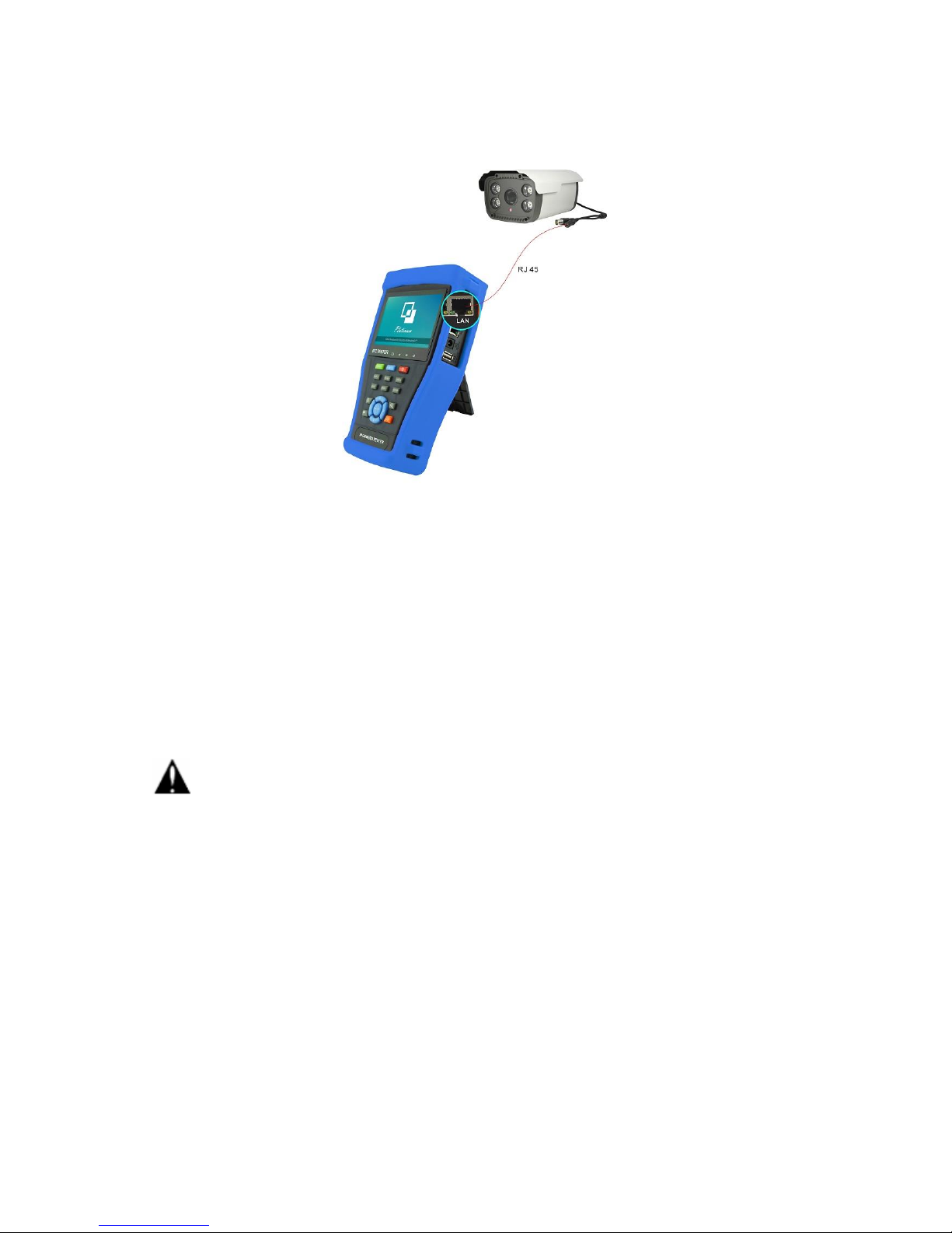
3.2.1 IP camera connection
Power an IP camera with an independent power supply, then connect the IP camera to the IPC tester’s
LAN port, if the link indicator of the tester’s LAN port is green and the data indicator flickers, it means
the IP camera and the IPC tester are communicating. If the two indicators don’t flicker, check if the IP
camera is powered on or the network cable is not functioning properly.
9
Note:1) If the IP camera requires PoE power, then connect the IP camera to the IP tester’s LAN port .
The tester will supply PoE Power for the IP camera. Click on the icon labeled POE to turn the PoE
Power off or on.
2) If use the tester’s menu to turn off the tester’s PoE power supply, the PoE switch and the power
sourcing equipment are allowed to connect to the tester’s PSE port, and the PoE power will be
supplied to the IP camera by the tester’s LAN port. On this condition, the tester cannot receive data
from IP camera, but the computer connected to the PoE switch can receive the data via the tester.
Warning: PoE switch or PSE power sourcing equipment only can be connected to tester “PSE IN”
port, otherwise will damage the tester.

10
3.2.2 Analog camera connection
(1) Connect the camera's video output to the IP tester’s VIDEO IN. The image will display on the tester
after pushing the PTZ icon.
(2) CCTV IP Tester “VIDEO OUT” interface connect to the Video input of monitor and optical video
transmitter and receiver, the image display on the tester and monitor.
(3) Connect the camera or the speed dome RS485 controller cable to the tester RS485 interface, (Note
positive and negative connection of the cable). Support RS232 PTZ controller, connect the RS232cable
to RS232 interface of the tester.
11
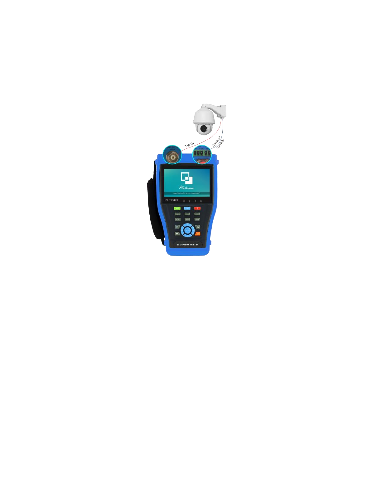
3.2.3 HD Coaxial camera connection
* CVI, TVI, AHD camera are classified as HD coaxial cameras. Hereby the following instruction of how
to connect TVI camera to the tester is also applied to CVI, and AHD camera.
(1) Connect the TVI camera's video output to the IP tester’s “TVI IN” interface, the image will display
on the tester. The tester only come with TVI input interface. There is no TVI output interface.
(2) Connect the TVI camera or the speed dome RS485 controller cable to the tester RS485 interface.
Support RS232 PTZ controller; connect the RS232 cable to RS232 interface of the tester.
12
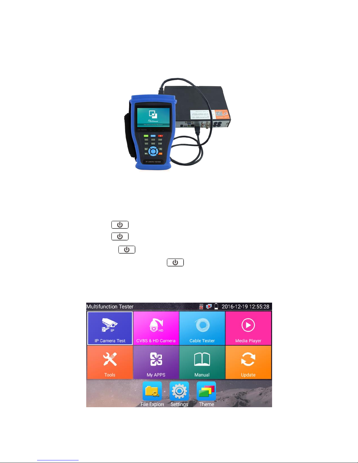
3.2.4 HDMI IN
DVR or other device’s HDMI in port connect to tester’s HDMI in port, the meter will display input
image.
3.3 OSD menu
Press the key 2 seconds to turn on
Press the key 2 seconds to turn off
short press the key to enter sleep mode, press it again to test if tester work abnormally
and cannot be turned off, Press the key several seconds to turn off, the tester reset.
3.3.1 Lite mode & Normal mode
Lite mode: You can easily find corresponding apps

13
In Lite mode, press the icon for several seconds, then you can move the icon to other apps
In lite mode, click the finger icon in the lower right corner to release lock icon, move icons and
change function icons sequence.
Normal mode
Tap the screen and slide left or right to change menu.
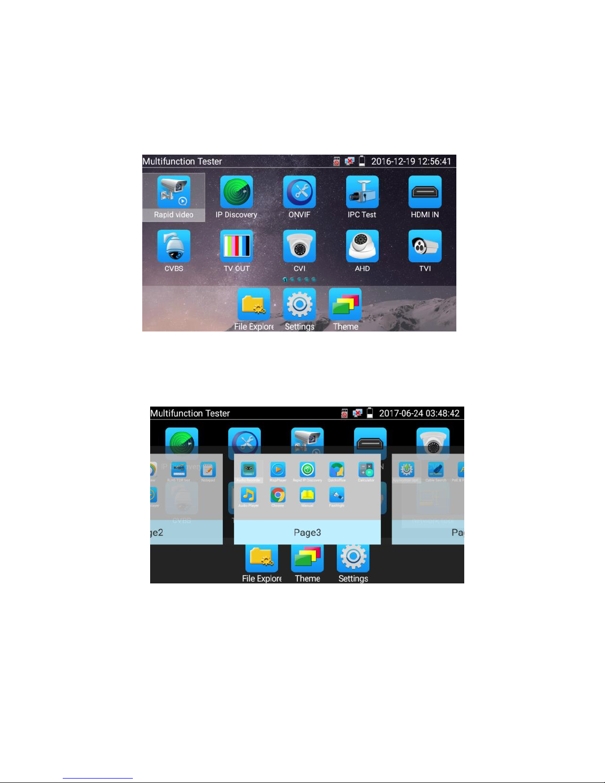
14
In normal mode, press icon several seconds, go screen management status. Change icons sequence
and move it to common tools bar.
You can move the icon to any pages, self-define the number of icons in any page. Make interface
simple and individualized.
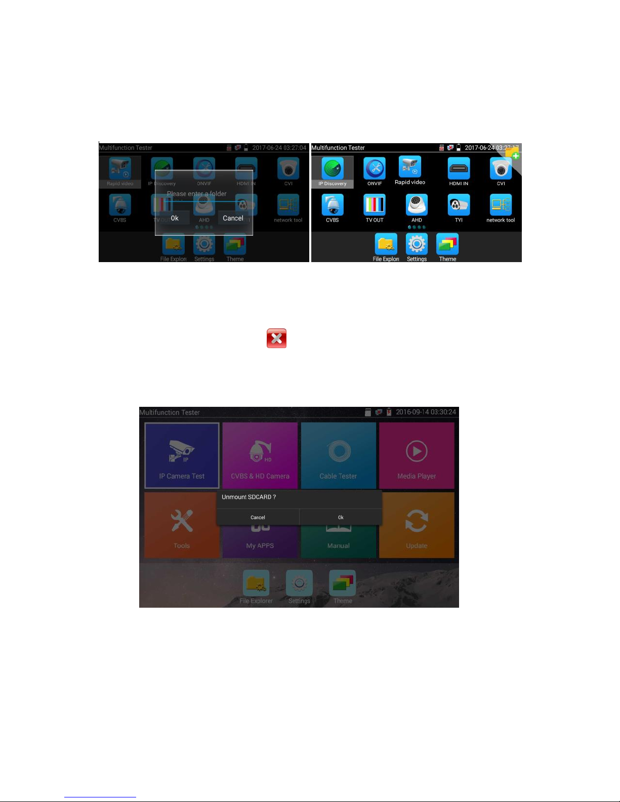
15
Create New Folder: Drag the icon to the folder in top right corner, enter the folder name. Icon will be
auto placed in the new named folder.
Press the folder several seconds, to change the folder name, you can move the icon out of folder, the
folder will be auto deleted until move out all icons.
Select Icons to enter, if quit, please click
Click SD card, install or remove SD card.
Table of contents


