Global Specialties DSC-5300 User manual

I
Content
Brief Introduction .......................................................................................................I
Chapter 1 Accidence ................................................................................................1
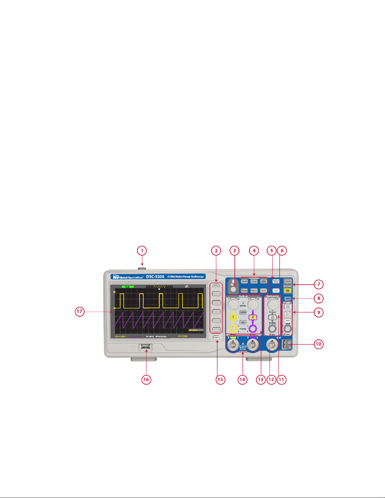
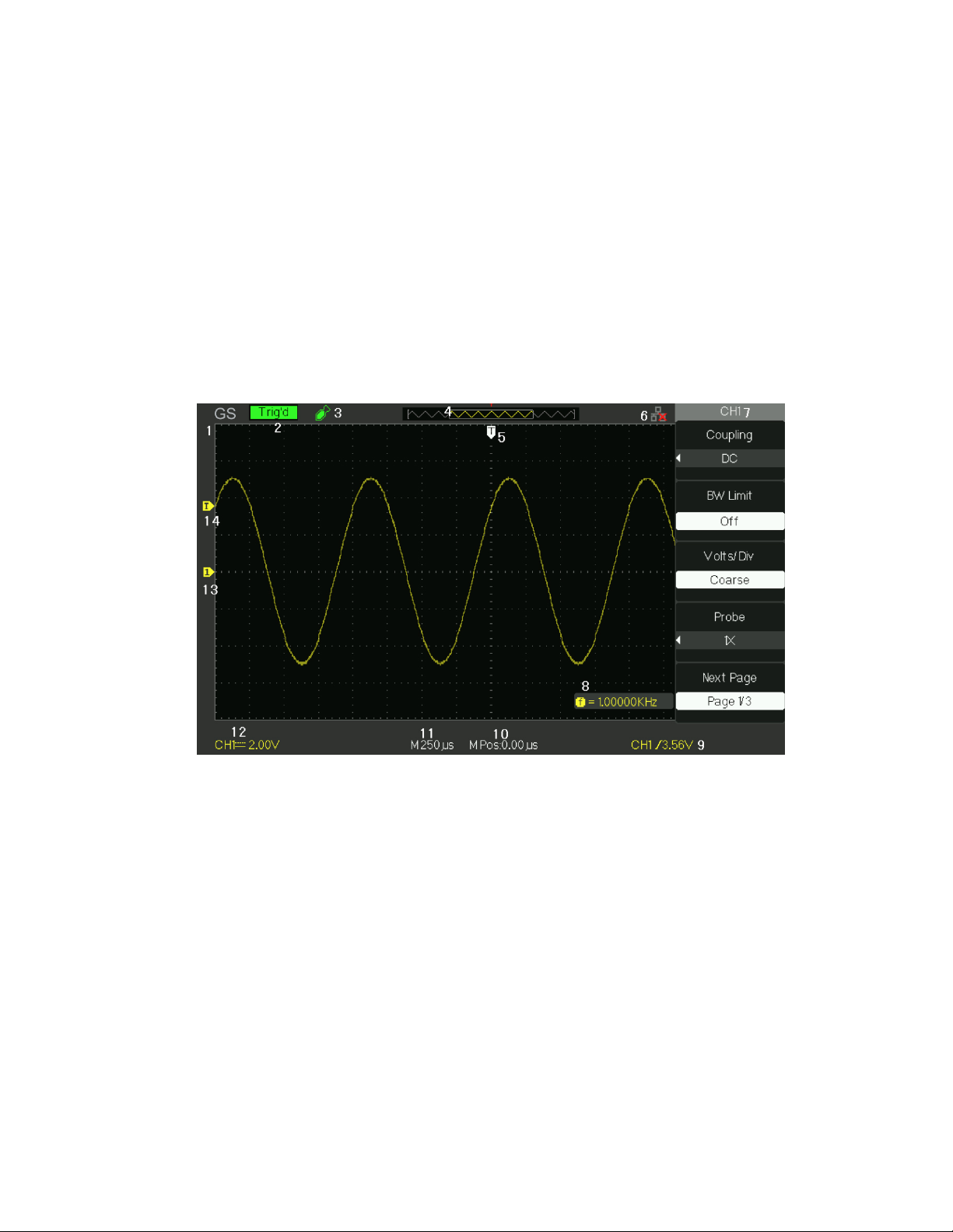
1.1 Accidence of Panel and Display Information .................................................................2
1.2 Function Checking..........................................................................................................5
1.3 Probe ...................................................................................................................7
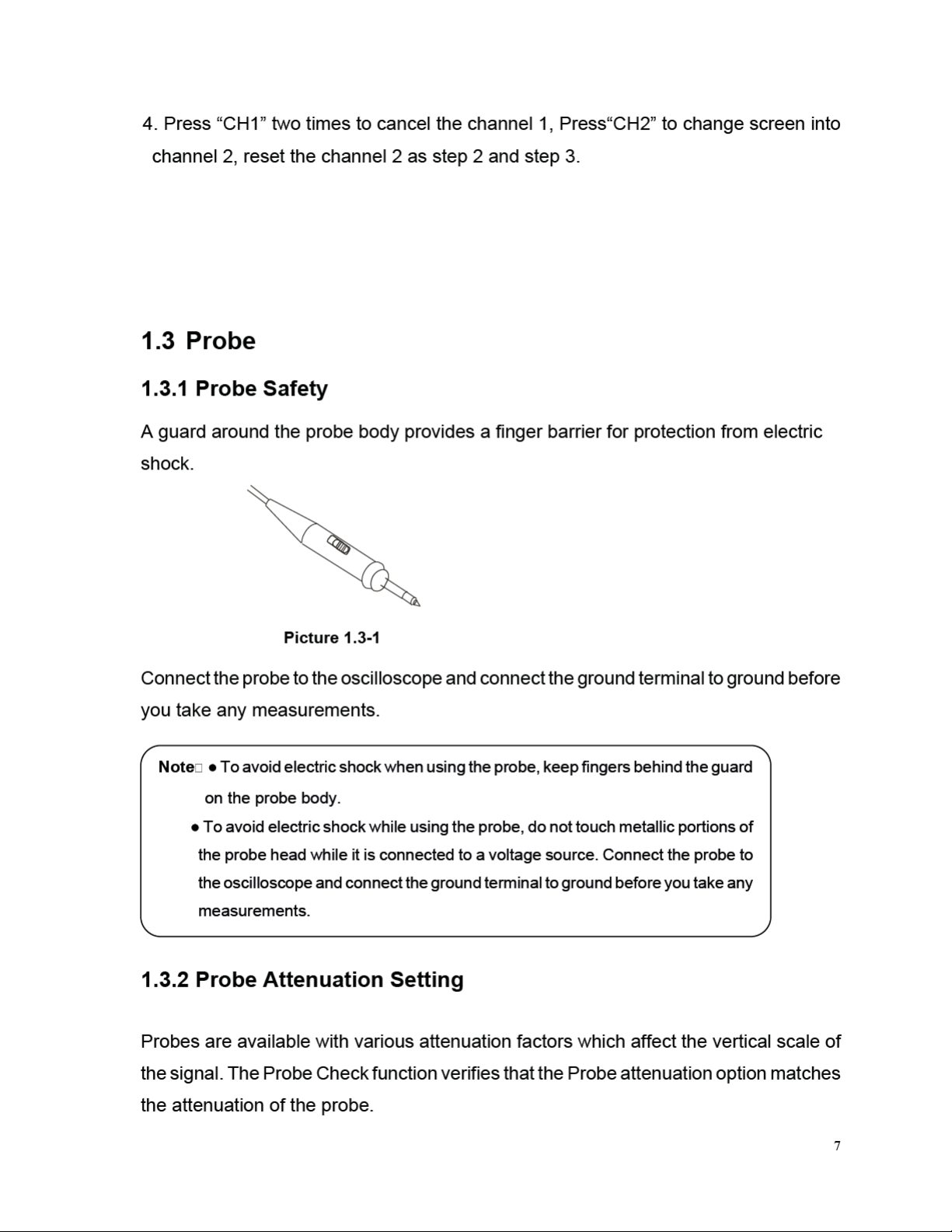
1.3.1 Probe Safety ..........................................................................................................7
1.3.2 Probe Attenuation Setting....................................................................................7
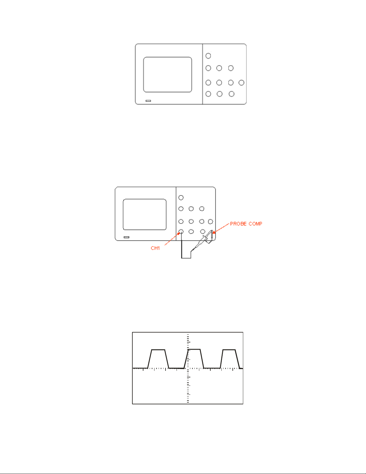
1.3.3 Probe Compensation............................................................................................8
Chapter 2 Functions Instruction and Operation........................................................9
2.1 Menu and Control Button .............................................................................................10
2.2 Connector......................................................................................................................12
2.3 Auto Setup ....................................................................................................................12
2.4 Default Setup ................................................................................................................14
2.5 Universal Knob .............................................................................................................15
2.6 Vertical System.............................................................................................................15
2.6.1 CH1, CH2 Channel .............................................................................................16
2.6.2 Using Vertical “Position” Knob and “Volt/div” Knob .......................................21
2.6.3 Math Functions ....................................................................................................22
2.6.4 Using Ref..............................................................................................................28
2.7 Horizontal System.........................................................................................................30
2.7.1 Horizontal Control Knob.....................................................................................31
2.7.2 Window Zone.......................................................................................................32
2.8 Trigger System..............................................................................................................33
2.8.1 Signal Source.......................................................................................................34
2.8.2 Trigger Type.........................................................................................................34
2.8.3 Coupling................................................................................................................47
2.8.4 Position .................................................................................................................48
2.8.5 Slope & Level.......................................................................................................48
2.8.6 Trigger Holdoff ........................................................................................49
2.9 Acquiring Signals System.............................................................................................49
2.10 Display System ...........................................................................................................55
2.10.1 X-Y Format.........................................................................................................59
2.11 Measure System..........................................................................................................59
2.11.1 Scale Measurement..........................................................................................60
2.11.2 Cursor Measurement........................................................................................60
2.11.3 Auto Measurement ...........................................................................................66
2.12 Storage System ...........................................................................................................72
2.13 Utility System .............................................................................................................85
2.13.1 System Status ...................................................................................................88
2.13.2 Language ...........................................................................................................88
2.13.3 Self Calibration ..................................................................................................89
2.13.4 Self Test ................................................................................................................90
2.13.5 Updating the System Software .......................................................................92
2.13.6 Pass/Fail.............................................................................................................92
2.13.7 Waveform Record.............................................................................................96
2.13.8 Recorder.............................................................................................................99
2.13.9 Remote Control ...............................................................................................102
Test Equipment Depot - 800.517.8431 - 99 Washington Street Melrose, MA 02176
TestEquipmentDepot.com

II
2.14 Online Help Function................................................................................................109
Chapter 3 Prompting Messages and Troubleshooting .........................................110
3.1 Prompting Messages:..................................................................................................110
3.2 Troubleshooting ..........................................................................................................112
Chapter 4 Service and Support ............................................................................114
4.1 Maintain Summary .....................................................................................................114
4.2 Contact GLOBAL SPECIALTIES .............................................................................114
Appendix A: Default Setup ...................................................................................115
Appendix B: Daily Maintain and Cleaning ............................................................117

Chapter 1 Overview
DSC-5300 Series Digital Oscilloscope is mini-type and portable bench type instruments,
which could be used for measuring as the GND voltage.
This Chapter shows you how to operate following tasks:
•Accidence of panel and Display information
•Simple checking of functions
•Matching probes attenuation coefficient
•Probe compensation

2
1.1 Overview of Panel and Display Information
1.1.1 Front Panel
It is important for you to understand the DSO’s front panel before operating it. The
following contents are the brief introduction for the front panel function, which is useful
to be familiar with the operation of the DSC-5300 Digital Storage Oscilloscope in short
time.
The oscilloscopes provides an easy-to-use front panel to convenience users to operate
them, the panel contains knobs and buttons. There is a list of five ashen buttons as menu
operational buttons on the right of display screen. You can set different options of the
current menu in virtue of them. Other buttons are function buttons; you can enter
different function menus or obtain given function application in virtue of them.
Picture 1.1-1 DSC-5300 Front Panel
Test Equipment Depot - 800.517.8431 - 99 Washington Street Melrose, MA 02176
TestEquipmentDepot.com

3
No.
Description
No.
Description
1
On/Off Button
10
Probe Compensator
2
Menu On/Off,
Menu Softkeys
11
Horizontal Controls
3
Intensity Adjustment
12
External Trigger Input
4
Control Keys
13
Vertical Controls
5
Default Setup Key
14
Input Channels
6
Help Key
15
Print Key
7
Run Control Panel
16
Front USB Connector
8
Autoset Key
17
Display
9
Trigger Control Panel
1.1.2 Back and Side Connections
The following images show back and side panel connection locations.
Picture 1.1-2 DSC-5300 Back and Side panel

4
1. Handle
2. AC Power Input Terminal
3. USB Device Connector
4. Pass/Fail Output Connector
5. LAN Port
6. Lock Hole
1.1.3 User display interface
Picture 1.1-3
1.Product Logo
Global Specialties is the registered trademark of our company.
2. Trigger status
Armed. The oscilloscope is acquiring pre-trigger data. All triggers are ignored in this
state.
Ready. All pre-trigger data has been acquired and the oscilloscope is ready to accept
a trigger.
Trig’d. The oscilloscope has seen a trigger and is acquiring the posttrigger data.
Stop. The oscilloscope has stopped acquiring waveform data.
Auto. The oscilloscope is in auto mode and is acquiring waveforms in the absence of

5
triggers.
Scan. The oscilloscope is acquiring and displaying waveform data continuously in scan
mode.
3. USB Host connected mark.
4.Waveform memory
Show the position of the current waveform in the memory of the oscillsocpe.
5.Trigger position.
Turn the HORIZONTAL POSITION knob to adjust the trigger position of the
waveform.
6.Show the LAN port.
Indicates the LAN port is connected.
ndicates the LAN port is disconnected.
7.Show the Channel symbol.
8.Readout shows trigger signal frequency..
9.Readout shows the trigger level value and trigger type..
10.Readout shows the trigger delay of waveform.
11.Readout shows the main time base setting.
12. Icon shows the channel setting.
13. Icon shows the channel offset position.
14. Icon shows the trigger level position
1.2 Function Checking
When you check whether or not the oscilloscope could work smoothly, please operate
as following:
1. Power On the oscilloscope.
Press “DEFAULT SETUP” to show the result of the self check. The probe default
attenuation is 1X.
Test Equipment Depot - 800.517.8431 - 99 Washington Street Melrose, MA 02176
TestEquipmentDepot.com

6
Picture 1.2- 1
2. Set the switch to 1X on the probe and connect the probe to channel 1 on the
oscilloscope. To do this, align the slot in the probe connector with the key on the CH 1
BNC, push to connect, and twist to the right to lock the probe in place. Connect the probe
tip and reference lead to the PROBE COMP connectors
Picture 1.2-2
3Press “AUTO” to show the 1 KHz frequency and about 3V peak-peak square wave
in couple seconds
Picture 1.2-3


9
Over Compensated Under
Compensated Correctly Compensated
Picture 1.3-3
4. If necessary, adjust your probe. Repeat as necessary.
Chapter 2 Functions Instruction and Operation
To use your oscilloscope effectively, you need to learn about the following oscilloscope
functions:
•Menu and control button
•Connector
•Auto Setup
•Default Setup
•Universal knob
•Vertical System
•Horizontal System
•Trigger System
•Acquiring signals System
•Display System
•Measuring waveforms System
•Utility System
•Storage System
•Online Help function
Test Equipment Depot - 800.517.8431 - 99 Washington Street Melrose, MA 02176
TestEquipmentDepot.com

10
2.1 Menu and Control Button
Showing as the following picture:
Picture 2-1
■Channel buttons (1, 2): Press a channel button to turn that channel ON or OFF and
open the channel menu for that channel. You can use the channel menu to set up a
channel. When the channel is on, the channel button is lit.
■MATH: Press to display the Math menu. You can use the MAH menu to use the
oscilloscopes Math functions.
■REF: Press to display the Ref Wave menu. You can use this menu to save and recall
four or two reference waveforms internal memory.

11
■HORI MENU: Press to display the Horizontal menu. You can use the Horizontal menu
to display the waveform and zoom in a segment of a waveform.
■TRIG MENU: Press to display the Trigger menu. You can use the Trigger menu to set
the trigger type (Edge. Pulse, Video, Slope, Alternative) and trigger settings.
■SET TO 50%: Press to stabilize a waveform quickly. The oscilloscope can
set the trigger level to be halfway between the minimum and maximum
voltage level automatically. This is useful when you connect a signal to the
EXT TRIG connector and set the trigger source to Ext or Ext/5.
■FORCE: Use the FORCE button to complete the current waveform acquisition
whether the oscilloscope detects a trigger or not. This is useful for Single acquisitions
and Normal trigger mode.
■SAVE/RECALL: Press to display the Save/Recall menu. You can use the Save/Recall
menu to save and recall up to 20 oscilloscope setups or waveforms in internal memory
(up to 20 waveforms) or on a USB memory device (limited by memory capacity of USB
device). You can also use it to recall the default factory settings, to save waveform data
as a comma-delimited file (.CSV), and to save or print the displayed waveform image.
■ACQUIRE: Press to display Acquire menu. You can use the Acquire menu to set the
acquisition Sampling Mode (Sampling, Peak Detect, Average).
■MEASURE: Press to display a menu of measurement parameters.
■CURSORS: Display the Cursor Menu. Vertical Position controls adjust cursor position
while displaying the Cursor Menu and the cursors are activated. Cursors remain
displayed (unless the “Type” option is set to “Off”) after leaving the Cursor Menu but
are not adjustable.
■DISPLAY: Press to open the Display menu. You can use the Display menu to set grid
and waveform display styles, and persistence.
■UTILITY: Press to open the Utility menu. You can use the Utility menu to configure
oscilloscope features, such as sound, language, counter, etc. You can also view
system status and update software.
■DEFAULT SETUP: Press to reset the oscilloscope’s settings to the default
factory configuration.

■
■
■
■
Picture 2-2
■
■
■
Note:
12 Test Equipment Depot - 800.517.8431 - 99 Washington Street Melrose, MA 02176
TestEquipmentDepot.com


14
Acquire Mode
Adjusted to Sampling
Display Format
Y-T
Display Type
Set to Dots for a video signal, set to Vectors for
an FFT spectrum; otherwise, unchanged
Vertical Coupling
Adjusted to DC or AC according to the input
signal
Bandwidth Limit
Off(full)
V/div
Adjusted
VOLTS/DIV adjustability
Coarse
Signal inverted
Off
Horizontal position
Center
S/div
Adjusted
Trigger type
Edge
Trigger source
Auto detect the channel which has the input
signal
Trigger slope
Rising
Trigger mode
Auto
Trigger coupling
DC
Trigger holdoff
Minimum
Trigger level
Set to 50%
2.4 Default Setup
The oscilloscope is set up for normal operation when it is shipped from the factory. This
is the default setup. To recall this setup, press the DEFAULT SETUP button. The options,
buttons and controls that change settings when you press the DEFAULT SETUP button,
refer to appendix B.
The DEFAULT SETUP button does not reset the following settings:
●Language option
●Saved reference waveform files
●Saved setup files
●Display contrast
●Calibration data

15
2.5 Universal Knob
Picture 2-5 Universal Knob
You can use the Universal knob with many functions, such as adjusting the holdoff
time, moving cursors, setting the pulse width, Setting the Video Linage, adjusting
the upper and lower frequency limit, adjust X and Y masks when using the pass/fail
function etc. You can also turn the “Universal” knob to adjust the storage position of
setups, waveforms, pictures when saving/recalling and to select menu options.
2.6 Vertical System
The vertical control could be used for displaying waveform, rectify scale and position.
Picture 2.6-1
Volt/div Knob
Vertical Position
Knob

16
2.6.1 CH1, CH2 Channel
Table 2-1 CH1, CH2 function menu 1:
Option
Setting
Introduction
Coupling
DC
AC
GND
DC passes both AC and DC components of
the input signal.
AC blocks the DC component of the input
signal and attenuates signals below 10 Hz.
GND disconnects the input signal.
BW limit
On
Off
Limits the bandwidth to reduce display noise;
filters the signal to reduce noise and other
unwanted high frequency components.
Volts/Div
Coarse
Fine
Selects the resolution of the Volts/Div knob
Coarse defines a 1-2-5 sequence.
Fine changes the resolution to small steps
between the coarse settings.
Probe
1X,5X
10X,50X
100X,
500X,1000X
Set to match the type of probe you are using
to ensure correct vertical readouts.
Next Page
Page 1/3
Enter the second page of the menu.
Table 2-4 CH1, CH2 function menu 2:
Option
Setting
Instruction
Invert
on
off
Turn on invert function.
Turn off invert function.
Digital Filter
Press this button to enter the “Digital Filter
menu”.(See table 2-5)
Next Page
Page 2/3
Enter the second page of the menu.
Table 2-5 Digital Filter function menu:
Option
Setting
Introduction
Digital Filter
On
Off
Turn on the digital filter.
Turn off the digital filter.
Type
Setup as LPF (Low Pass Filter).
Setup as HPF (High Pass Filter).
Setup as BPF (Band Pass Filter).
Setup as BRF (Band Reject Filter).
Upper_limit
Turn the “Universal” knob to set upper limit.
Lower_limit
Turn the “Universal” knob to set lower limit.
Return
Return the digital filter main menu.
Test Equipment Depot - 800.517.8431 - 99 Washington Street Melrose, MA 02176
TestEquipmentDepot.com


Table of contents
Other Global Specialties Test Equipment manuals