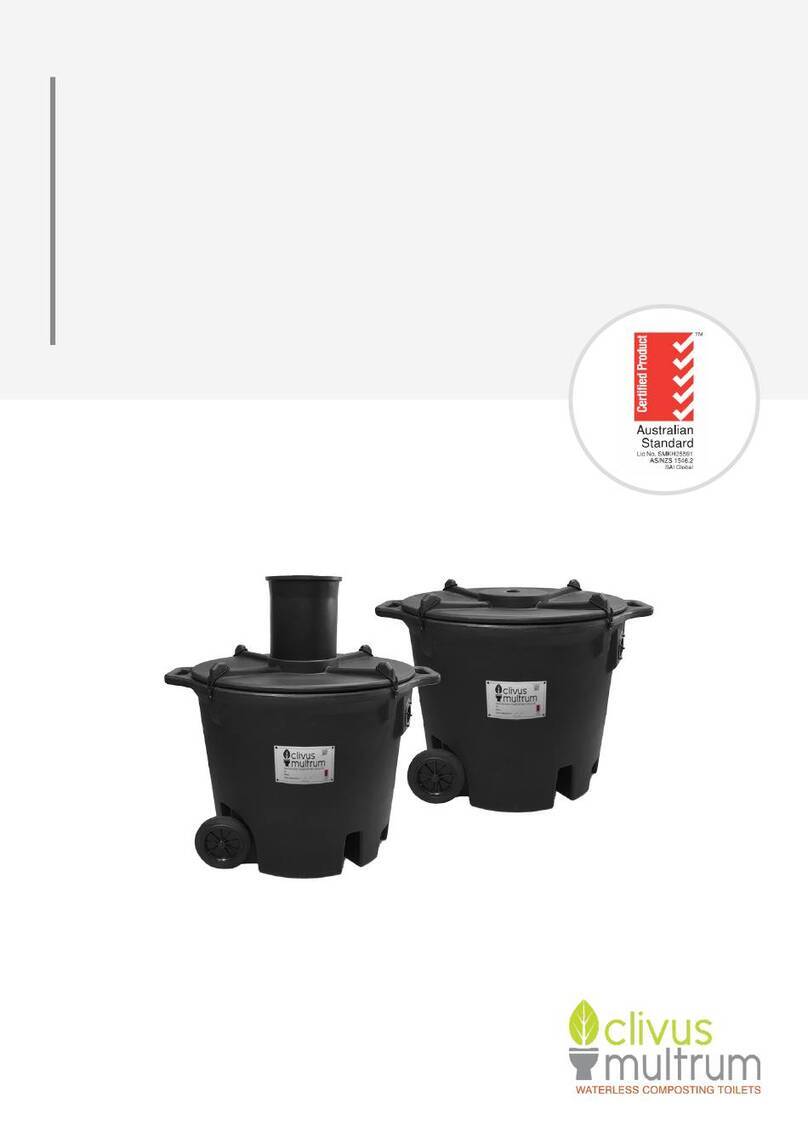
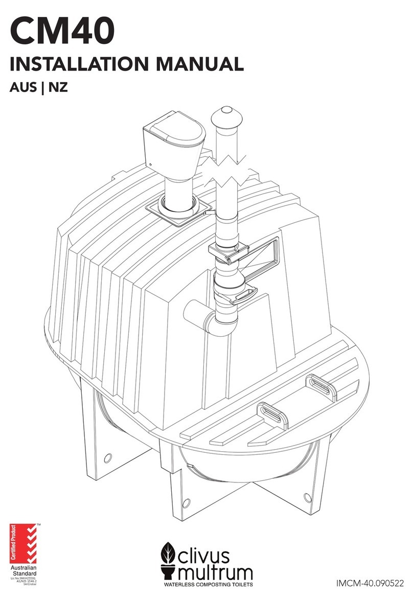
clivus multrum CM8 User manual

go green pay less no mess
waterless
composting
toilet systems
Manufacturers of Australia;s Leading
Commercial Environmental Toilet Systems
INSTALLATION MANUAL | COMMERCIAL UNITS
For Models:
CM8 | CM10 | CM14
CM20 | CM40 | CM60
p 1300 13 81 82
www.clivusmultrum.com.au
f 07 3889 6149
PO Box 5467 Brendale QLD 4500
3/14 Hinkler Court Brendale QLD 4500

TABLE OF CONTENTS
1. RECEIVING THE SHIPMENT P 2
2. INSTALLATION SUMMARY P 2
3. TYPICAL CONFIGURATION OF COMPONENTS P 3
4. COMPONENT IDENTIFICATION P 4
5. TOOLS & MATERIALS REQUIRED P 6
6. PREPARATION P 7
7. TANK SUPPORT P 8
8. EXCESS LIQUID DRAIN INSTALLATION P 9
9. TOILET CHUTE & PEDESTAL P 11
10. SIGNAGE P 12
11. INSTALLATION OF VENTILATION SYSTEM P 13
12. POWER TO THE FAN P 14
13. VENTILATION SYSTEM ALTERNATIVES P 14
14. STARTER-BED OF ORGANIC MATTER P 15
15. STARTING THE COMPOSTING PROCESS P 15
WARRANTY P 16
INSTALLATION CERTIFICATION P 17
go green pay less no mess
PAGE 1

go green pay less no mess
1. RECEIVING THE SHIPMENT.
Your Clivus Multrum toilet system is shipped as an assembled compost
tank with most of the Clivus components packed inside. All components
can be removed without disassembling the tank. The toilet chute will fit
through the inspection door. The pedestal package is usually strapped to
the compost tank.
Please refer to Section 3 and 4 to identify the components and check them
against the packing slip supplied. If there has been any damage, please
contact Clivus Multrum immediately on (07) 3889 6144.
Damage, shortages and discrepancies must be reported to your local
representative or Clivus Multrum Australia within 7 days of receiving
shipment. Any damage or missing parts not reported within 7 days from
receipt of goods will not be the responsibility of Clivus Multrum Australia.
2. INSTALLATION SUMMARY.
Read through the entire installation manual thoroughly before commencing
assembly.
»Ensure the tank is in a position so that all toilet chutes will
be vertical and over the tank in the preferred position/s.
»Ensure the tank is level, stable and supported.
»Mark and cut holes in the floor for the toilet chute(s).
»Mark and cut holes in the tank top.
»Insert toilet chute/s.
»Install pedestal/s.
»Install the vent system.
»Install the liquid end-product drain pipe and absorption/transpiration
trench.
»Connect fan to power source.
»Check everything is sealed.
»Place a starter-bed of bulking agent in the unit.
»Moisten bulking agent before use of toilet.
»Add starter bacteria after a short period of use.
PAGE 2

go green pay less no mess
3. TYPICAL CONFIGURATION OF COMPONENTS
Diagram not to scale. PAGE 3

go green pay less no mess
TAN K
INSPECTION DOOR
NA M EP LATE
ACCESS DOOR TO FINISHED
COMPOST
INLET AIR GRILLE
VENT SYSTEM ITEMS
Fan in housing
transformer
chinamans hat rain cover
turbovent (optional)
MAINTENANCE RAKE
LIQUID DRAIN
4. COMPONENT IDENTIFICATION
PAGE 4

go green pay less no mess
PEDESTAL & SEAT
WASTE CHUTE
TANK CHUTE COLLAR
SIGNS (NOT SHOWN)
VENT PIPE SECTIONS
ROOF FLASHING
VENT SUPPORT BRACKETS
DRAIN PIPING
DRAIN CONNECTOR &
BENDS
TRENCHING ARCH
TRENCHING END CAPS
VENT & DRAIN KIT (OPTIONAL ITEMS)
PAGE 5

go green pay less no mess
5. TOOLS & MATERIALS REQUIRED.
5.1 TOOLS REQUIRED:
»Spirit level
»Scissors or cutting knife
»Screwdriver (Philips head and plain)
»Jigsaw (an angle grinder or a drill can also be used to
cut large holes).
»Please use safety glasses.
»Dril l
»Tape measure
»Caulking gun
»Felt tip or crayon marker
»Masonry drill and bit (if installing onto concrete floor)
»Spade
»Ladder
5.2 MATERIALS REQUIRED:
»Starter bulking material (if not purchased from Clivus).
See Section 14.
»Water for wetting starter material.
»Timber for tank rear support if required.
»Additional 40 mm PVC pipe, couplings and bends if
absorption trench is to be located some distance away
from tank.
»In poor soil conditions, extra length of trenching arch
may be required (500 x 230mm)
»Pipe bends if needed for vent pipe.
In addition, if the Vent & Drain Kit was not purchased with
your unit you will need:
»150mm vent pipe lengths to suit (DWV class is
recommended).
»Vent pipe supports and wall/roof flashings to suit.
»40mm DWV pipe and fittings to connect to a sullage
disposal system.
PAGE 6

go green pay less no mess
6. PREPARATION
»Climate Considerations.
Any decomposition process works better where temperatures are warmer rather
than in cold temperatures, this is also true of composting toilet. The compost
pile will generate its own heat, but is cooled by exposure to its surroundings
and ventilation air drawn through the tank.
Over the winter months the composting process slows or can even temporarily
stop where temperatures in the pile drop below 4ºC. Once the warmer weather
comes again the rate of decomposition increases to normal levels. The nominal
capacity of your Clivus Multrum system is based on an annual mean ambient
temperature of 18ºC. In Australia this usually means that in colder weather if
the daily mean temperature is less than 13ºC for an extended period of time
steps may need to be taken to ensure that the tank can handle its full nominal
use capacity.
Assuming that you have already purchased your composting toilet tank and
that you have chosen the size tank that will take into account the above
factors, the composting process can be further improved through the use of
natural or passive heating.
As the composting tank is black, it will absorb heat from the sun. Simply by
installing the compost bin on the north side of the house will make a dramatic
difference in the composting process by increasing daytime temperatures
inside the tank. In addition, a translucent hatch and enclosure can be installed
around the compost bin. In really cold areas another successful method of
heating the composting tank is to duct warm air from another source such as
a green house or a solar air heater, or to locate a hot water storage tank in the
same room. In extreme alpine conditions it may be necessary to insulate the
tank itself in addition to the above.
»Positioning the system components.
After fully reading this manual and before starting the installation roughly
position all the major components. It is always a good idea to have an overall
picture of the project before starting and do the following:
»Position the compost tank.
Check the position planned for the toilet chute (refer Section 9). The toilet
chute must be positioned over the top of the compost tank. For less
maintenance of the compost pile, the optimum location for the chute/s to
enter the tank is mid-width, in the rear half of the tank. A clearance of at least
150mm from edge of chute to edge of tank-top is desirable to avoid rapid
build up of the pile against the sides.
Check there are no major support beams or pipes or wires that are in the way
of the toilet chute.
Locate where the vent pipe is to run (refer Section 11).
Where mains power is to be used, check that a power point has been installed
near the location for the ventilation fan.
Locate where the excess liquid drainpipe and trench is to go.
If there is very little room between the top of the tank and the floor of the
building, the order of the installation can be changed as follows: Firstly, cut
the pedestal hole in the floor of the building (refer Section 9) and then mark
the hole position on the tank when the tank is in position, but before the tank
is secured into the ground. After the tank has been marked, it can be removed
from under the building and then cut the hole in the tank and fit the chute
collar before replacing the tank.
PAGE 7

go green pay less no mess
7. TANK SUPPORT.
The composting tank must be supported by either packed earth with the
tank placed on a base of sand, or a wooden frame on a solid base; e.g. a
concrete slab. Insulation between the tank and the concrete slab will reduce
heat loss and aid the composting process.
NOTE: The tank and enclosure should be protected from surface and
floodwater.
7.1 EARTH SUPPORT [SEE FIGURE 2].
The surface must be rock free and smooth to prevent possible puncture of
the tank. Stand the tank on 50-75 mm thick bed of sand, crusher dust fines
or similar. To avoid excessive soil pressure on the tank, the CM8 and CM10
can be buried only up to the tank join line, and the larger tanks should only
be buried to a maximum depth of 500mm.
In order to ensure stability of the surrounding earth, a retaining wall may be
required. All back fill around the tank should be rock free. When the tank
is partially dug into the ground, take steps to ensure that heavy rain will
not cause a build up of surface water in the area around the tank Ensure
the tank cannot slide forward by mounding sand or gravel around the front
of the tank as in Figure 2 above. Ensure that the position for liquid end-
product drain and trench has been marked.
SLOPING SITE INSTALLATIONS
Earth
Backfill
Sand
Layer
Tank
Drain Ground & Surface
Water Drain
See table for
minimum floor
clearance
FIGURE 2
PAGE 8

go green pay less no mess
8. EXCESS LIQUID DRAIN INSTALLATION.
The excess liquid fittings are to be installed after the tank is in final position.
STEPS FOR INSTALLATION
1. Smear some sealant around the washer (both sides) that is provided
with the plug-and-waste fitting.
2. Put the washer over the plug and waste and then from the inside of
the tank, push the plug and waste through the hole in the tank.
3. From the outside of the tank, screw the clamping collar onto the
protruding thread. This collar should only be hand tightened.
4. Screw on the female pipe adapter.
The tank is now ready to have the 40mm PVC excess liquid drain pipe connected.
The optional Vent and Drain Kit available from Clivus Multrum provides a length of
trenching arch, end-caps, 1mtr of 40mm waste pipe and 2 x 45º elbows. (Shown on
page 5).
7.2 WOODEN SUPPORT
This is required only for the CM60 tanks, in installations where the sloping
rear wall is not buried or supported by a soil mound. Build a wooden full-
width support for the sloping bottom of the tank. Ensure the stand cannot
move backwards and that the tank cannot move forward. Attach wooden
locks to the floor in front of the tank, or connected back to the rear frame
so the tank will not move away from the rear support.
Wooden support
on a solid base
Rear support
PAGE 9

go green pay less no mess
EXCESS LIQUID ABSORPTION TRENCH.
This is the normal method for disposal of excess liquid, but refer to council
permit for any specific requirements. These instructions apply to installation of
the drain kit items available from Clivus Multrum. In some locations it may be
desirable or necessary to connect the excess liquid drain to a greywater system
or an alternative disposal method complying with AS / NZS 1547:2012.
Dig a trench in a position located in front of the liquid end product drain.
The trench is to be located in soil of good permeability and in a position
where ground water will not flood the unit. If there is some doubt as to the
permeability of the soil extra trenching length may be required especially if
a handbasin or other fittings will also drain to the same trench. The liquid
leaving the compost unit when in use is not expected to exceed 1 litre per day
per resident. In many domestic installations there is no excess liquid at all. In
public-use facilities, the liquid disposal system should be sized to allow for up
to 25 litres per 100 toilet uses.
Trench dimensions and construction are to be in accordance with AS / NZS
1547:2012, as shown below.
Dimensions in mm.
DURABLE SELF-SUPPORTING ARCH TRENCH.
It is important to ensure that the trench is level along its length. Ensure
the liquid drain pipe slopes away from the compost tank. Trench should be
protected from surface water and flooding, and vehicle traffic.
PAGE 10

go green pay less no mess
9. TOILET CHUTE & PEDESTAL.
READ ALL STEPS BEFORE STARTING!
IF WORKING ACCESS UNDER THE FLOOR IS VERY LIMITED YOU MAY NEED TO CHANGE
THE SEQUENCE OF THE FOLLOWING STEPS TO SUIT.
STEP A. Packed with this manual there is an A3 paper template for cutting the
chute hole to correct size. Front and back are marked on the template to assist with
placement from wall.
STEP B. Place the template on the floor where the pedestal will be installed. The
minimum clearance needed from chute hole to the back wall is 120mm. Trial the pedestal
in position by placing it over the template. Allow sufficient clearance from the rear of
the pedestal to the back wall of the toilet room to ensure the seat will stay up when
in the raised position. Also allow at least 200mm from the side walls. Note: greater
clearances are required if access is required for disabled persons.
Fix template to floor, or mark through it where the hole is to go on the floor. Check
there are no under-floor support joists, pipes or wiring that may be damaged by cutting
the hole. Extra braces in the floor may be needed if a joist must be cut - check with a
builder if necessary.
Check the chute will drop vertically into suitable location on compost tank, and is not
too close to posts, walls or other obstructions for the tank.
STEP C. Cut the floor hole closely along the template or mark. This will allow a
sliding fit for the chute and provide the correct support shoulder for it.
STEP D. Slide the toilet chute down through the hole in the floor (flanged end of
the chute is the top end). Ensure the chute sits vertical and has no more than 5mm of
sideways play in the hole.
Note: If the floor of the building is high above the top of the tank a chute extension
piece/s may be needed. Extra lengths are available from your supplier, and will fit into
each other. Joints should be screwed with short self-tapper screws, and sealed with
silicon. If more than 2 chutes are joined then additional support straps or brackets are
needed to support their weight from the building frame, instead of hanging only by
the top chute.
STEP E. Once the compost tank has been correctly positioned, using the outside
of the toilet chute as a template mark and cut the toilet chute hole in the top of the
tank. This need not be a close fit, as the chute collar will provide the seal.
STEP F. Enlarge the hole in the rubber chute collar so it will stretch snugly around
the toilet chute without gaps. A good pair of scissors will do this, or a cutting blade.
PAGE 11

go green pay less no mess
STEP G. Cutting the toilet chute to length:
Place the toilet chute into the floor hole and through the compost tank top. Open the
tank inspection door and from inside the tank mark the cut-off length on the toilet
chute, allowing 80-100mm drip edge below the lowest part of the tank top. Remove
chute and cut off at mark.
STEP H. Fix the toilet chute and collar in place:
1. Having cut the toilet chute at the correct length, push the toilet chute back
through the hole in the floor, through the toilet chute collar and into the compost bin.
The top shoulder of the toilet chute should sit flush against the floor. Lift the toilet
chute slightly and put sealant between the toilet chute and the floor then press chute
down again to seat firmly onto the floor.
2. Bend and work the metal edging strip of the chute collar to match the shape of
the tank top for a good seal. (This step may be easier to do after the pedestal is fixed
and holds the chute in place)
3. Run a bead of silicon sealant around the underside edge of the collar.
4. Using the ½” stainless screws provided, secure the collar to the tank top by
screwing through the metal edging strip.
STEP I Fix the Toilet Pedestal:
1. With the chute in final position, place the pedestal in position by matching the
groove in its base to the upturned flange lip of the chute.
2. Carefully drill small screw-starter holes into floor through the 4 pedestal fixing
holes, taking care not to scratch or move pedestal. If your drill is too large to access
these holes then mark the hole locations,remove the pedestal to avoid damage, and
drill suitable floor holes for fasteners. Remove the pedestal to apply sealant as follows.
3. For sealing of the chute to the pedestal, place a large bead (8-10mm) of silicon
sealant around the inside corner of the chute.
4. On underside of pedestal, place a large bead (5mm) of silicon sealant along the
bottom of the V-groove in the pedestal. Also run a small bead of sealant around the
outer edge of the pedestal base, to seal it to the floor and prevent ingress of liquids
and grime from the outside.
5. Carefully place the pedestal into its final position over the chute and fixing
holes, then fasten the base to the floor with appropriate fasteners (screws if wooden
floor, concrete anchors if concrete slab).
6. Smooth sealant at the two exposed joints (on inside and exterior) and wipe
off excess. Do not use solvents to clean excess sealant from the pedestal as it may
damage surface.
7. Attach the toilet seat to the pedestal top using the supplied fixings.
10. SIGNAGE
1. Affix user plaques within easy view i.e. near the toilet paper holder
2. Apply the “No Smoking / Please close lid” sticker to the inside of the toilet lid.
PAGE 12

go green pay less no mess
11. INSTALLATION OF VENTILATION SYSTEM.
Note: As air flow is essential to the operation of the unit, the fewer bends that are used
when installing the vent system the better.
The following instructions relate to use of the vent pipe sections available from Clivus
Multrum in the optional Vent & Drain Kit. If this kit is not used, installer must provide
a length of 150mm pipe to suit. We recommend PVC pipe, grade DWV for its strength
and long life.
1. Plan the vent pipe layout.
• The hole for the vent pipe should preferably be at the side of the tank towards
the front of the unit near the inspection door, as far as practical from the
nearest chute entry. This is so fresh air is drawn up the back vent and over the
fresh material before it is drawn up the vent pipe.
• The vent pipe may enter the tank vertically through the top, or horizontally
through the side wall near the tank top.
• To avoid woodshavings buildup, fan location is better the higher it is
positioned, though it still needs to be accessible so a good place to put the fan
housing is at the top end ot the first length of pipe. The wiring junction box
should be protected from the weather.
• The vent pipe should project approximately 1000mm above roof line.
2. Mark and cut a 160 mm hole in the appropriate position of the compost bin
using the pipe as a template.
3. Mark and cut the vent collar skirt so that it fits neatly around the vent-pipe and
slide it onto the bottom pipe section.
4. Insert vent pipe 50mm into the tank and support in position.
5. Check that the arrow on the fan housing is pointing up the vent pipe and not
back towards the compost bin, now mount the fan housing onto the vent pipe. Note
the two screws that hold the cover of the fan housing on. Twist the fan housing
around so a screw driver can reach the screws should the fan need to be checked or
changed over.
6. Connect upper sections of vent pipe. There is no need to glue joints, however
you may do so if desired. The vent pipe should be supported against the wall of the
building with the brackets provided, (or suitable alternatives) to carry the weight of the
complete vent system. The tank must not carry any weight from the vent systems.
7. It may be necessary to cut through the roof or eaves of the house. Before
cutting through the roof use a spirit level to ensure that the vent pipe is vertical. A
vertical vent pipe is not necessary for the operation of the system but aesthetically it
looks much better.
8. Once the vent pipe is in place, cut the roof flashing to size, slip it over the
exterior vent pipe and seal to roof sheeting with sealant and self-tapping screws or
rivets. A tile roof may require an alternative type of flashing to suit.
9. Install the ‘china hat’ rain cap or optional turbo vent with 3 self-tapping screws
on to the top of the vent pipe. (A turbo vent is usually only required when the fan is
run off Daylight Solar, or with a ‘passive’ ventilation system).
10. Now seal the vent collar to the tank with the supplied SS screws (10g x 1/2”)
and sealant, once the vent pipe is secured in final position.
11. Run some small beads of silicone around the joints on the vent pipe and
especially around the join of the fan housing.
PAGE 13

go green pay less no mess
12. POWER TO THE FAN.
The 240 / 12 volt transformer normally provided by Clivus Multrum plugs straight into a
normal 240 volt power point (GPO) to provide low voltage power for the fan.
Due to the low voltage and current from the transformer it is not necessary to have an
electrician install the fan and wiring from the transformer to the fan, however, the 240v
powerpoint MUST be installed by a licensed contractor. Note: The vent fan should
normally be wired for 24 hour operation.
The 12 volt wires from the transformer must be connected to the junction box on the
fan housing. At first glance the wire coming from the transformer looks like two black
wires joined together. A closer inspection will reveal that one of the black wires has a
fine white line on it.
Remove the cover of the small white junction box that is fixed to the fan housing.
Under this white cover there are two wires from the fan. Join the wire from the
transformer that has a fine white line on it to the red wire (positive) of the fan: join
the plain black wire from the transformer to the plain black wire (negative) of the fan.
Check that the fan operates, then replace the cover on the white junction box. If the
wiring is done in reverse the fan will simply not work.
There is a switch on the power transformer to change the output voltage from 12 volts.
Use of a lower voltage will still give adequate airflow for the system in most cases,
however, a setting of less than 6 volts may not operate the fan. We recommend the fan
is initially run at 12v.
13 VENTILATION SYSTEM ALTERNATIVES
There are two basic alternatives for ventilation:
1. Solar - where a 12-volt or 24-volt fan in the vent pipe is run by solar equipment
either 24hr or Daylight operation.
2. Passive - where there is no electrical fan in the system
13.1 SOLAR POWER OPTION
A separate sheet showing how the solar panel is connected to the fan has been
included with this manual if you have chosen this option. Use of a wind driven turbo
vent is recommended to assist ventilation when no power is available from the solar
supply. Other installation details are unchanged.
13.2 PASSIVE VENTILATION OPTION
It should be noted, that with a passive vent system, a continuous odour-free operation
cannot be guaranteed. If a passive system is to be installed it is important to keep the
toilet room separate from the main house and encourage as much natural draft through
the vent as possible.
This option is normally used only where the location is remote and/or has no power
source available, or if you are installing your toilet in a weekender that is visited
infrequently.
With this option, no electric fan is installed to draw air through the unit and therefore it
is not necessary to install the fan housing. If for some reason you do wish to install the
fan housing, then the fan should be removed so that the fan is not a restriction to the
airflow. If possible, the vent pipe should be straight without any bends in it.
To help maintain good airflow, a turbo vent can be fastened on top of the vent pipe
to draw air when there is wind blowing outside. The pipe’s natural chimney effect is
improved by painting the vent pipe black to absorb more heat from the sun, heating up
the air inside the pipe and enhancing the drawing efficiency.
PAGE 14

go green pay less no mess
14. STARTER-BED OF ORGANIC MATTER
Note : this is a crucial part of the installation process and must be completed before
the unit is used.
We recommend wood shavings as the starter-bed material or bulking agent. In some
cases due to supply problems or personal preference it is not practical to use wood
shavings. The reason we recommend them is because they are high in carbon and are
of a good texture so as to trap oxygen.
Alternative bulking agents are dicussed in the Operating Manual.
Unsatisfactory materials for the starter-bed include: large quantities of lawn clippings,
fine sawdust, large wood chips and long stemmed grasses. These materials decompose
but in your CLivus may have a tendency to form solid “clumps”.
Spread the bulking material in the tank bottom so as to cover the lower edge of the air
ducts as shown in the diagram below.
Appproximate volume required is:
CM8 | 0.25 cubic metres
CM10 | 0.3 cubic metres
CM14 | 0.4 cubic metres
CM20 | 0.5 cubic metres
The bottom of the air ducts must be
covered and woodshavings should come
up above the inside of the front
stainless steel air duct.
15. STARTING THE COMPOSTING PROCESS
Once the woodshavings have been added, dampen down with water (spray with a hose
through the top inspection door). This breaks the surface tension and allows the
bulking material to begin absorbing the urine that will enter the tank. If this is not done
liquid can simply run off the organic material without soaking through (in much the
same way as a very dry teatowel will not dry wet dishes very well).
Clivus Multrum provides a packet of starter bacteria with your new system. In order for
this to be effective, it is necessary to have some waste in place to provide nutrients
before the bacteria is added to your unit. We therefore suggest that the toilet is used
in the normal way for say 7 - 10 days (depending on usage level) before the bacteria is
added.
Hydrate the supplied Clivus compost starter bacteria in a bucket of water for 10
minutes or longer, then add bacteria to the toilet.
CONGRATULATIONS! You have now completed the installation of your new
composting toilet. Now you can sit back and admire your handiwork and enjoy the
knowledge that from now on you will be saving your valuable water supply and doing
your bit in keeping our waterways free of pollution.
IT IS NOW ESSENTIAL THAT YOU FAMILIARISE YOURSELF THOROUGHLY
WITH YOUR OPERATING AND MAINTENANCE MANUAL. You will quickly learn
how you should look after your Clivus to ensure iot operates reliably and efficiently for
years to come.
PAGE 15

go green pay less no mess
LIMITED WARRANTY
Purchaser:
Address:
Tank Serial#:
lnstalled by:
Date of Shipment:
Date of lnstallation:
Clivus Agent Distributor:
Clivus Multrum Australia warrants the unit identified above, including integral components thereof,
against defects in material and workmanship under normal use, operation and maintenance for a
period of five (5) years from the date of shipment by Clivus Multrum Australia as provided below.
PURCHASERS OBLIGATION: Purchaser must use and maintain the unit strictly in accordance with
the installation, operation and maintenance instructions provided. Any claim under this limited warranty
must be submitted in writing to Clivus Multrum Australia prior to the expiration of the warranty period.
To be valid, any such claim must include the Tank serial # and the name of the agent distributor and
the installer.
CLIVUS MULTRUM AUSTRALIA’S OBLIGATION: Should Clivus Multrum Australia determine
that a valid limited warranty claim has been submitted, the company shall correct the defect by suitable
replacement or repair at the company’s expense. Any replaced or repaired components will carry a
further limited warranty on the same terms as set forth herein starting from the date of replacement or
repair.
EXCEPTIONS: Fans, pumps or motors shall have a limited one year warranty. Solar cell panels are
warranted by their manufacturer and not by Clivus Multrum Australia. Where components are
warranted by the manufacturer, Clivus Multrum Australia will warrant that component for the same term
as the manufacturer except that the maximum term of warranty by Clivus Multrum Australia shall be
five (5) years.
EXCLUSIONS: a) Any repairs or replacements necessitated by failure to conform to the
installation, operation and maintenance instructions supplied in the
respective manuals.
b) Any repairs or replacements necessitated by vandalism, neglect, abuse,
misuse or failure to adequately service the unit.
c) Deterioration of accessory items due to normal wear and tear or exposure
to the elements.
OTHER WARRANTIES: This warranty is in lieu of and excludes all other warranties expressed or
implied by operation of law or otherwise, including any warranty that the unit is merchantable or suitable for
the customer’s particular purposes. Clivus Multrum Australia neither assumes nor authorises any
representative or other person to assume for it any obligation or liability other than that which is
expressly set forth herein.
REMEDIES: Correction of defects for the period of the time provided herein shall constitute fulfillment
of all obligations of Clivus Multrum Australia for damages whether based on contract, negligence or
otherwise with respect to or arising out of the sale, installation, condition, or operation of the unit. The
remedies provided herein shall be the Purchaser’s sole remedies for breach of any warranty. Clivus
Multrum Australia shall not be liable in contract or in tort to the Purchaser or any other person for
special, indirect or consequential damages, such as, but not limited to, damage to or loss of the use of
other property or equipment, loss of profits or revenues, or claims by Purchasers or tenants of the
Purchaser for service interruptions or losses of any kind.
PAGE 16

go green pay less no mess
INSTALLATION CERTIFICATION (FOR OWNER’S RECORDS ONLY)
To validate your warranty this check list should be completed by an authorized representative of Clivus
Multrum Australia. lt should be returned to Head Office at the address below only when making a
claim:
PO BOX 5467 BRENDALE QLD 4500
1. Tank enclosure - access space for maintenance provided.
2. Tank enclosure - 60 square cm opening provided to allow air to enter the tank enclosure or alternative air
source attached directly to the tank end-product compartment.
3. Tank support - entire bottom of tank supported by durable materials capable of supporting 2,000kgs/
m2, having a smooth surface. Sloping rear of tank supported {where applicable).
4. Front baffle - if not factory installed, bolted into place and sealed to the tank.
5. Air ducts - installed open side down between front baffle and rear of tank.
6. Rear baffle - installed.
7. End product drain - installed liquid to be drained by gravity.
8. No end product drain - hand or electric pump installed and operable.
9. Liquid end product - connected to subsurface disposal or storage.
10. Tank loaded with organic matter - thoroughly moistened woodshavings or other starter bed (please
specify: )
spread evenly in the tank bottom covering the’forward part of the air ducts and extending up behind the
front baffle; compost starter added.
11. Chute and Vent holes in Tank - in accordance with lnstallation Manual.
12. Chute and Vent Pipe - adequately support and no weight carried by tank shell.
13. Chute and Vent sections - jointed together and secured.
14. Toilet pedestal - fastened to floor and sealant applied.
15. Urinal (if applicable) - installed with piping sloping continuously toward tank, entering tank at rear of
toilet chute, connected with sealant.
16. Power for fan - AC provided or photovoltaic system installed.
17. Fan - installed in vent in location convenient for access. Adequate draft occurring.
18. Vent to extend minimum 600mm above roof.
19. Flashing and rain cover - installed on exterior vent.
20. User plaque - attached in toilet room.
21. “Please keep lid closed” signs attached to inside of toilet seat lid.
22. Name of person responsible for maintenance:
23. Tank Serial#
I certify that the above named Clivus Multrum installation has been inspected by me and
conforms to all specifications, instructions for installation and recommendations as oulined
Clivus lnstallation Manual, except where I have noted and given sufficient reason.
Date lnstalled by:
Signature of Clivus Agent/Distributor:
PAGE 17
Other manuals for CM8
4
This manual suits for next models
5
Table of contents
Other clivus multrum Toilet manuals
clivus multrum
clivus multrum CM8 User manual
clivus multrum
clivus multrum CM20 User manual
clivus multrum
clivus multrum CM8 User manual

clivus multrum
clivus multrum M100 User manual
clivus multrum
clivus multrum CM HP User manual
clivus multrum
clivus multrum CM14 User manual
clivus multrum
clivus multrum NL2 User manual
clivus multrum
clivus multrum CM8 User manual
clivus multrum
clivus multrum HIGH PROFILE User manual
clivus multrum
clivus multrum CM14 User manual
