Cloos Arc Flash 4 evo User manual
Operating
instructions
and
spare parts list
Welding helmet
CLOOS Arc Flash 4 evo
Rev. 1.2
Original instructions
2
The CLOOS welding filters are tested for eye protection by the following
notified body: ECS GmbH, Obere Bahnstrasse 74, 73431 Aalen, Germany,
notified body 1883, that provides approval and continual quality system
under the control of the European Commission, the German Ministry for
Work and the Central Office of the Provinces.
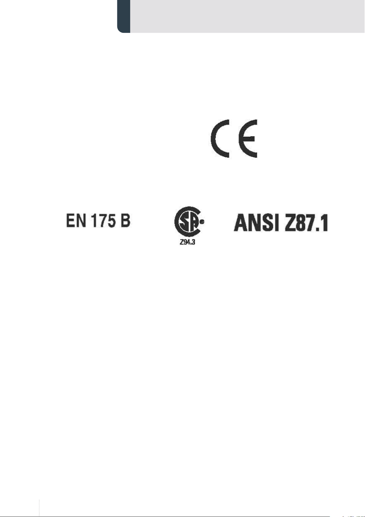
European Conformity mark.
This confirms that the product fulfills the requirements of the
Directive 89/686/EWG
Notified Body ECS GmbH
Registration Number 1883
Obere Bahnstrasse 74
73431 Aalen
GERMANY
Filter Marking Explanation
CE 4/9-13 WT 1/1/1/2/379
4 - light state scale number
9- lightest dark state scale number
13 darkest state scale number
WT - Manufacturer identification
1 - Optical class
1 - Diffusion of light class
1 - variation in luminous transmittance class
2 – Angle of Dependence classification
379 - Number of the standard

3
Content
1. General information................................................................................. 4
1.1 Operating instructions.......................................................................................... 4
1.2 Explanation of symbols......................................................................................... 4
1.3 Limitation of liability.............................................................................................. 5
1.4 Copyright ..................................................................................................................... 5
2. Safety ........................................................................................................... 6
2.1 Proper use.................................................................................................................... 6
2.2 Reasonably foreseeable misuse......................................................................... 6
2.3 Personnel requirements........................................................................................ 6
2.4 Hazards......................................................................................................................... 7
3. Technical data ............................................................................................ 8
3.1 Environmental condition...................................................................................... 8
3.1.1 Ambient temperature............................................................................................ 8
3.1.2 Humidity...................................................................................................................... 8
4. Function and use....................................................................................... 9
4.1 Operation..................................................................................................................... 9
4.1.1 Adjustment of headgear....................................................................................... 9
4.1.2 Setting the shade ...................................................................................................10
4.1.3 Recommended shadelevels ...............................................................................11
4.1.4 Setting the filter......................................................................................................11
4.1.5 Setting the delay ...................................................................................................12
4.1.6 Testing settings.......................................................................................................12
5. Servicing and maintenance .................................................................. 13
5.1 Replacing the outer spatter lens.....................................................................13
6. Spare parts................................................................................................ 14
4
1. General information
1.1 Operating instructions
These operating instructions contain important information for the safe,
efficient handling of the device. Compliance with all of the safety instruc-
tions and operating instructions contained herein is a pre-condition for
safe working with the device.
Illustrations in these instructions are intended to provide a basic under-
standing, and may differ from the actual design of the device. Claims
cannot be derived therefrom.
Information manual for the welder protective helmet complying with Para-
graph 1.4 of Appendix ll of the EC regulations. The welding helmet is a high
quality product that contribute to the comfort and safety of the welder.
The welding helmet may be used only in connection with arc welding.
1.2 Explanation of symbols
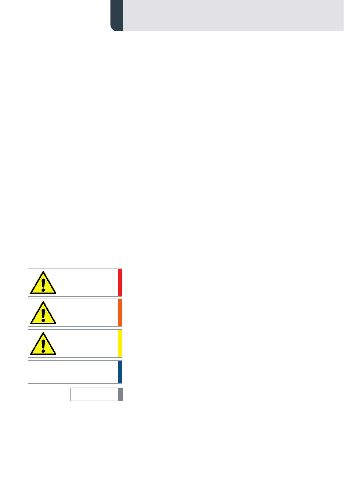
Warning and safety instructions in the manual are identified by means of
pictograms and highlighted in a colour-coded block.
Warning and safety instructions which draw your attention to basic haz-
ards are additionally marked with signal words which express the level of
damage. These are categorised as follows:
The signal word indicates a hazard with a high level of risk, which, if not
avoided, leads to fatal or severe injury.
The signal word indicates a hazard with a moderate level of risk, which, if
not avoided, can lead to fatal or severe injury.
The signal word indicates a hazard with a low level of risk, which, if not
avoided, leads to minor or moderate injury.
The signal word indicates a hazard without risk of a physical impairment,
which, if not avoided, can lead to property damage.
Tips and recommendations as well as information for efficient and
smooth operation.
DANGER!
WARNING!
CAUTION!
ATTENTION!
NOTICE

5
1.3 Limitation of liability
All information and notes in this manual were compiled taking into con-
sideration the applicable standards and regulations and the state of the
art, as well as our many years of knowledge and experience .
The manufacturer assumes no liability for damages caused by:
• Non-observanceofthemanual
• Improperuse
• Useofuntrainedandnon-instructedpersonnel
• Unauthorisedalterations
• Technicalchanges
• Useofunauthorisedspareparts
1.4 Copyright
This document is protected by copyright.
The unauthorised transfer of these instructions to third parties, reproduc-
tion of any kind and in any form, even in excerpts, as well as the recovery
and/or notification of the content is prohibited without the written per-
mission of the publisher.
Infringements of this trademark will be subject to compensation for dam-
ages. All rights to further claims reserved.
6
2. Safety
2.1 Proper use
The device is only to be used for the following purpose:
The device affords reliable protection for the eyes whilst electric arc
welding. It offers permanent protection against UV/IR rays, heat & sparks
in any state from the clear to dark.
The welding helmet can be used for the following applications:
• Electrode
• MIG
• Mag
• Tig
The welding filters operate well under extreme low lighting and very
strong sunlight.
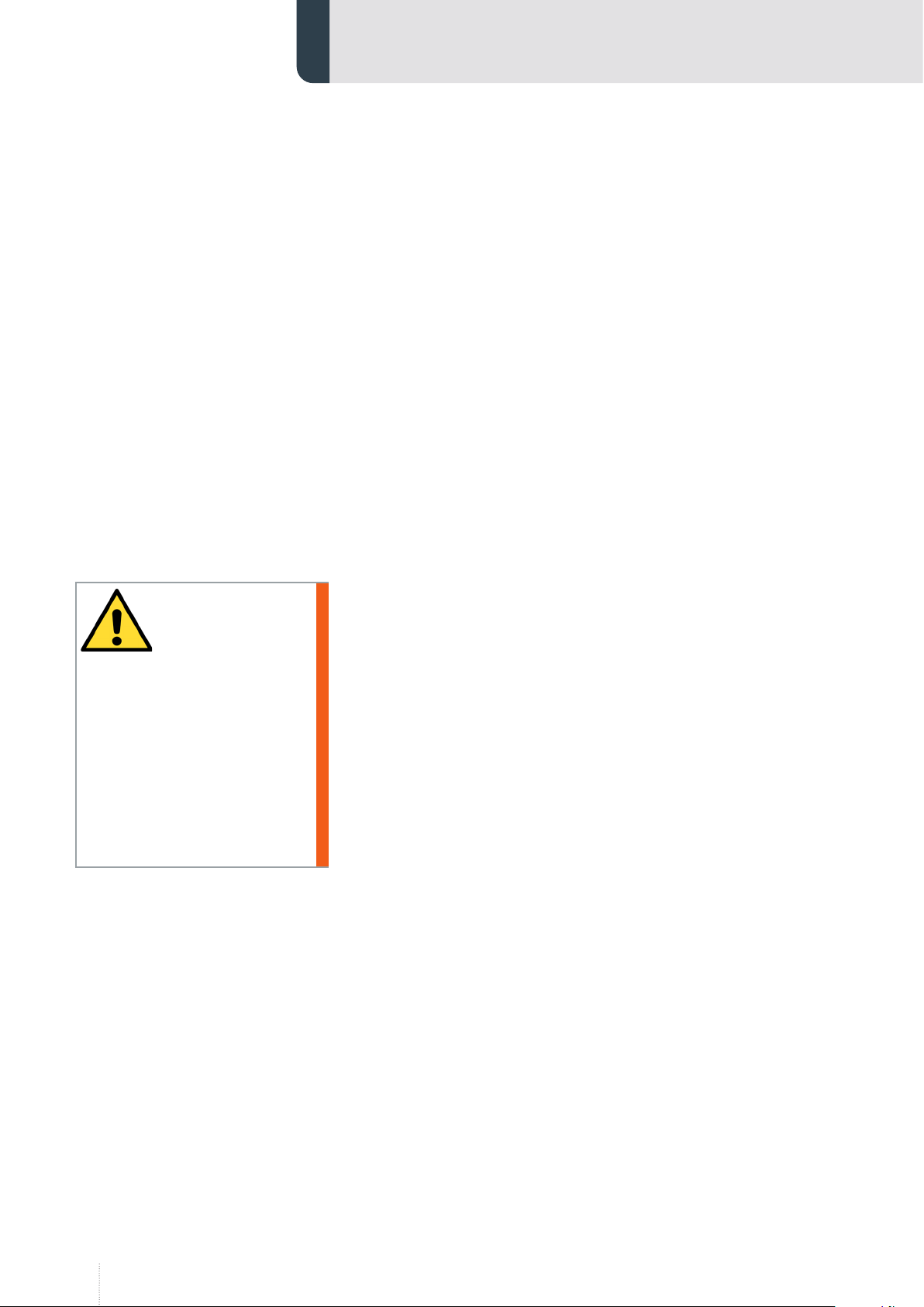
Risk from improper use!
Any use of the device other than the intended purpose can lead to hazard-
ous situations.
• Thedeviceshouldnormallyonlybeusedinaccordancewiththeinfor-
mationinthisdocument,inparticularwithrespecttocompliancewith
theapplicationlimitvaluesgiveninthetechnicalspecifications.
• Refrainfromanyuseofthedevicewhichdiffersorextendsbeyond
theselimits.
• Donotconvert,retrofitorotherwisealterthestructureorindividual
fittedcomponentswiththeaimofalteringthescopeofapplicationor
usabilityofthedevice.
Claims of any kind for damages caused by improper use are excluded.
2.2 Reasonably foreseeable misuse
The device is intended exclusively as protection for the eyes against UV/IR
rays, heat & sparks in any state from the clear to dark whilst arc welding.
They are not suitable for use with laser systems and oxy-acetylene (gas
welding) applications. The welding filter must not be used for any other
purpose other than welding. They should never be used as sunglasses
when driving as this could lead to incorrect identification of the colour of
traffic light.
2.3 Personnel requirements
Work may only be performed by a trained specialist. All personnel involved
must be instructed with regard to the safety requirements, safety regula-
tions and operational instructions which must be applied in their work.
WARNING!
7
2.4 Hazards
The warning and safety notices listed here and in the operations chapters
of these instructions must be observed in order to prevent potential harm
to health and hazardous situations.
Radiation
Ultraviolet and infrared radiation are released during welding. This can
cause a painful inflammation of the cornea and irreparable damage to the
lens of the eye leading to cataracts.
• Protectskinandparticularlytheeyes.Keepeyedropsandskincream
withahighsunprotectionfactoravailable.
• Donotlookdirectlyatweldingrayswithunprotectedeyeswhenthearc
strikes.
• AlwaysusesafetyglassesaccordingtoDINEN166andDINEN379in
yourwelder’sprotectiveshieldorhelmet.
• ProtectotherpersonsinthevicinityoftheweldingareafromUVrays
andspatterbysuitable,non-flammablepartitionwalls.
• Alwayswearsafetyglasseswithsideprotectionwhenyouareinan
areawhereweldingtakesplaceorwhereslagisremoved.
Allergic reaction
Materials that may get in contact with the wearers skin could cause Aller-
gic reactions to susceptible individuals.
• Ifthecontactcan´tbeavoided,atalktoadoctoraboutusingcreamsis
recommendedtokeeptheskinsafe.
DANGER!
WARNING!

8
3. Technical data
3.1 Environmental condition
3.1.1 Ambient temperature
Welding helmets and filters only resist a certain amount of heat. Please do
not place them near naked flames or hot work areas etc.
Operating temperature of electronic filter -5°C…55°C.
3.1.2 Humidity
The auto-darkening filters fitted in the helmets are not waterproof and will
not work properly if they have been in contact with water.

9
4. Function and use
Welding helmets afford reliable protection for the eyes whilst electric
arc welding. They offer permanent protection against UV/IR rays, heat &
sparks in any state from the clear to dark. The protection shades of the
welding helmets have been chosen to avoid eye damage caused by the
welding arc.
Welding helmets allow the welder to see the point of arc strike more pre-
cisely. This leads to a real time saving. The helmet does not have to be flip-
ped up and down during welding, both hands are kept free and because of
the helmets lightweight fatigue is reduced.
The helmet is available in 2 options. The helmet can be supplied with or
without UVIR shade 5 side windows – the side windows giving the user a
degree of side vision whilst still giving protection from the welding rays.
4.1 Operation
Before using the helmet for the first time the protective films must be
removed from the front spatter lens. The films cannot be removed from
the front spatter lens with the lens in place. Please follow the instructions
below to remove the spatter lens, see chapter „5.1 Replacing the outer
spatter lens“ on page 13
4.1.1 Adjustment of headgear
Welding helmets are equipped with a comfortable headgear that can be
adjusted in three different ways.
Push and Move
„Head height“
Push and turn
„Head size“
Rake
Adjustment
10
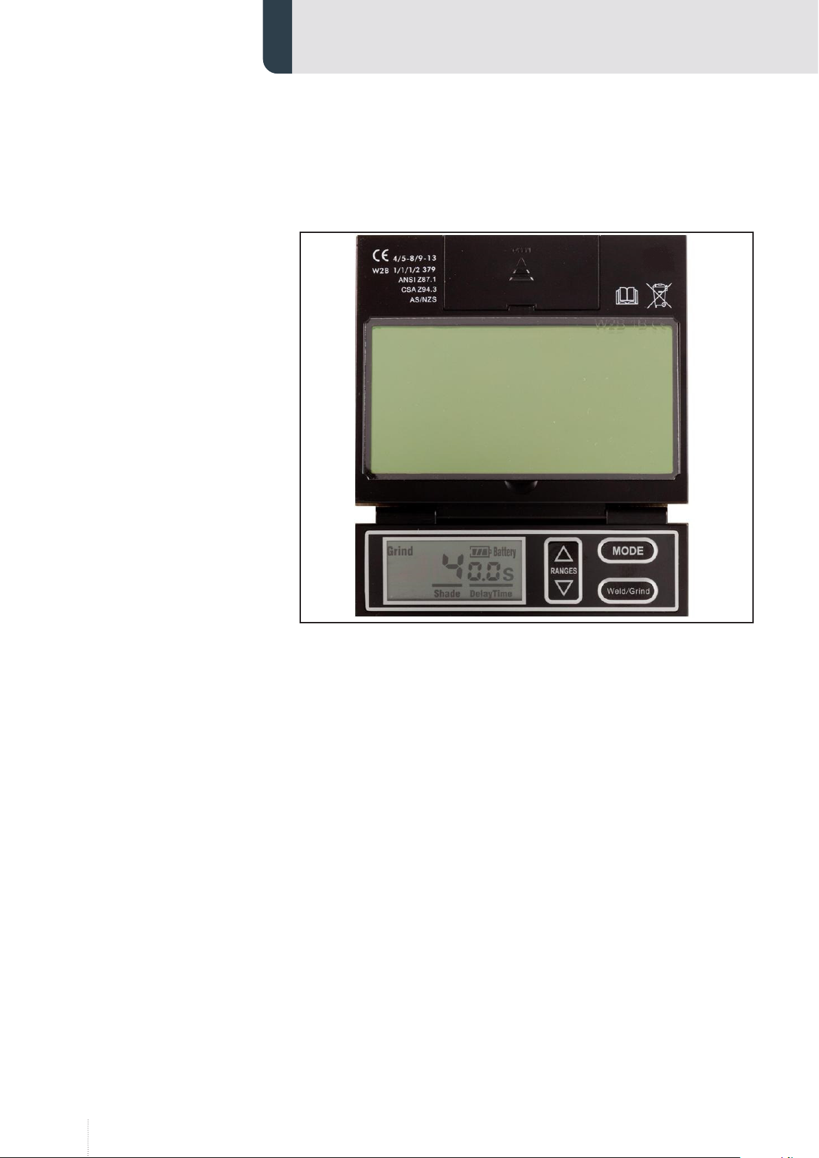
4.1.2 Setting the shade
On the welding helmet, the welding shade is selected by pushing the
"Weld/Grind" button.
2 ranges of welding shades are available:
• From DIN 5 to DIN 8, and
• From DIN 9 to DIN 13,
Select the welding shade by pushing the arrows on the Range button, up
and down to clear or darken the welding shade.
The welding helmet also offers a Grinding Mode with the "Weld/Grind"
button. The shade is then blocked in a shade DIN 4.

11
4.1.3 Recommended shadelevels
The most suitable shadelevel settings can be found on this chart or choose
using your experience. This setting can also be made manually during the
welding process.
4.1.4 Setting the filter
To allow the filter to switch, the sensors on the front of the filter must not
be covered. The filter then switches to the dark state when the arc strikes
and to the clear state when it stops. The filter switches to the light state
when the welding arc stops.
Once you have selected the Sensitivity MODE, push the UP arrow to the
maximum setting. Depending upon the surrounding light the filter will
switch to the dark state or will flicker (if the surrounding light is very low,
the filter may not switch to the dark state). Push the DOWN arrow until the
filter switches to the clear state.
The filter is now set to its optimum sensitivity (According to the surround-
ing light conditions).
Current internally in amperes
Welding process or related techniques
0,5 2,5 10 20 40 80 125 175 225 275 350 450
1 5 15 30 60 100 150 200 250 300 400 500
Flux core electrodes
Fluxed stick electrodes 9 10 11 12 13 14
MIG
Steels, alloyed steels, copper and its
alloys etc.
10 11 12 13 14
MIG
Aluminium, copper, nickel and other
alloys
10 11 12 13 14 15
TIG 9 10 11 12 13
MAG
Constructions steel, hardened and
tempered steels, Cr-Ni-steel, Cr-steel and
other alloyed steels
10 11 12 13 14 15
Electric arc compressed air joining 10 11 12 13 14 15
Plasma cutting 11 12 13
Micro-plasma welding 2,5
45 6 7 8 9 10 11 12 13 14 15

12
4.1.5 Setting the delay
The clearing delay can be adjusted manually by selecting the Delay MODE
and then by pushing the arrows on the "Ranges" button, up and down, to
select a delay between a fast clear (0.1 s) up to a slow clear (1.9 s).
4.1.6 Testing settings
Before use of the welding helmet the auto darkening filter (ADF) and hel-
met needs to be checked according to the following procedure:
• Check outer protection lens is clean and can be seen through.
• Ensure the the sensors are covered in any way and are clean.
• Once these checks have been carried out you can now test the ADF.
Select the darkest setting (shade 13) and set the sensitivity to the highest
setting. Now point the sensor towards a light source such as an overhead
light, lamp etc. The ADF should now switch to the dark state (please note if
the ADF is stored in a dark area away from light it may need to be left out
in strong light for 20 minutes to absorb power, if after 20 minutes if the
ADF does still not react then there is an issue with the sensor). Once the
filter is in the dark state you can check the shade variation is functioning
correctly, simply adjust the shade. By doing this, the shade should get ligh-
ter. If the shade does not appear to alter then you have an issue with the
shade variation.
To test the delay function set the delay to the maximum setting. Now
move the filter sensor away from the light source it should take 1 second to
return to the light state, now alter the delay setting to the minimum and
repeat the process, the time taken to return to the clear state should be 0.1
second. If the ADF does not react in this way then there is an issue with the
delay function.
Testing the sensitivity. Set the sensitivity to minimum setting and point
the ADF at the light source you used to test the other functions. If filter
switches to dark state, move away until the filter returns to clear state.
Slowly reduce the sensitivity until the filter switches to dark state (if it does
not, then move closer to the light until it reacts). If the ADF does not react,
then there is an issue with the light sensors.
If any of the functions fail during test or in use then please do not use the
ADF and contact your local distributor.

13
5. Servicing and maintenance
If used properly the welding filter requires no further maintenance during
its lifetime. The filter should be cleaned when changing the protection
lenses.
This can be done by any of the following ways:
• Wipe with a clean, dry piece of cloth.
• Clean with a piece of smooth cloth moistened with pure alcohol.
• Clean with a commercial disinfectant
If a filter should be replaced on a welding helmet, use exclusively certified
products. (DIN-CE marks). We recommend the use of CLOOS welding filters
in all CLOOS Arc Flash helmets.
The filter itself contains no special or toxic products and can be disposed of
in the same way as other electronic devices.
Always make sure that the helmet is equipped with an outside and inner
lens (in front of the filter on the outside and on the inside behind the filter).
These protection lenses must be replaced if damaged in any way (see over-
leaf). They are consumables and should checked and replaced regularly.
5.1 Replacing the outer spatter lens
Ensure that the helmet is always equipped with an Outside Lens (before
the filter, on the outside of the helmet) and an Inner Lens (behind the filter,
inside the helmet). These protection lenses must be replaced if broken,
damaged or covered with welding spatter to such an extent that vision is
impaired. Inner and Outer Lenses are consumables and must be replaced
regularly with certified CLOOS spare parts (CE marked).
To insert the new outer protection 4lens the filter must be removed by
unscrewing the two retaining screws 8from the inside of the helmet 1.
The old protection lens can then be removed and the new lens inserted
followed by the light seal cradle 6, ADF 7, inner protection lens 5and
then the ADF retaining frame 8and finally replace the two retaining
screws (see drawing).
14
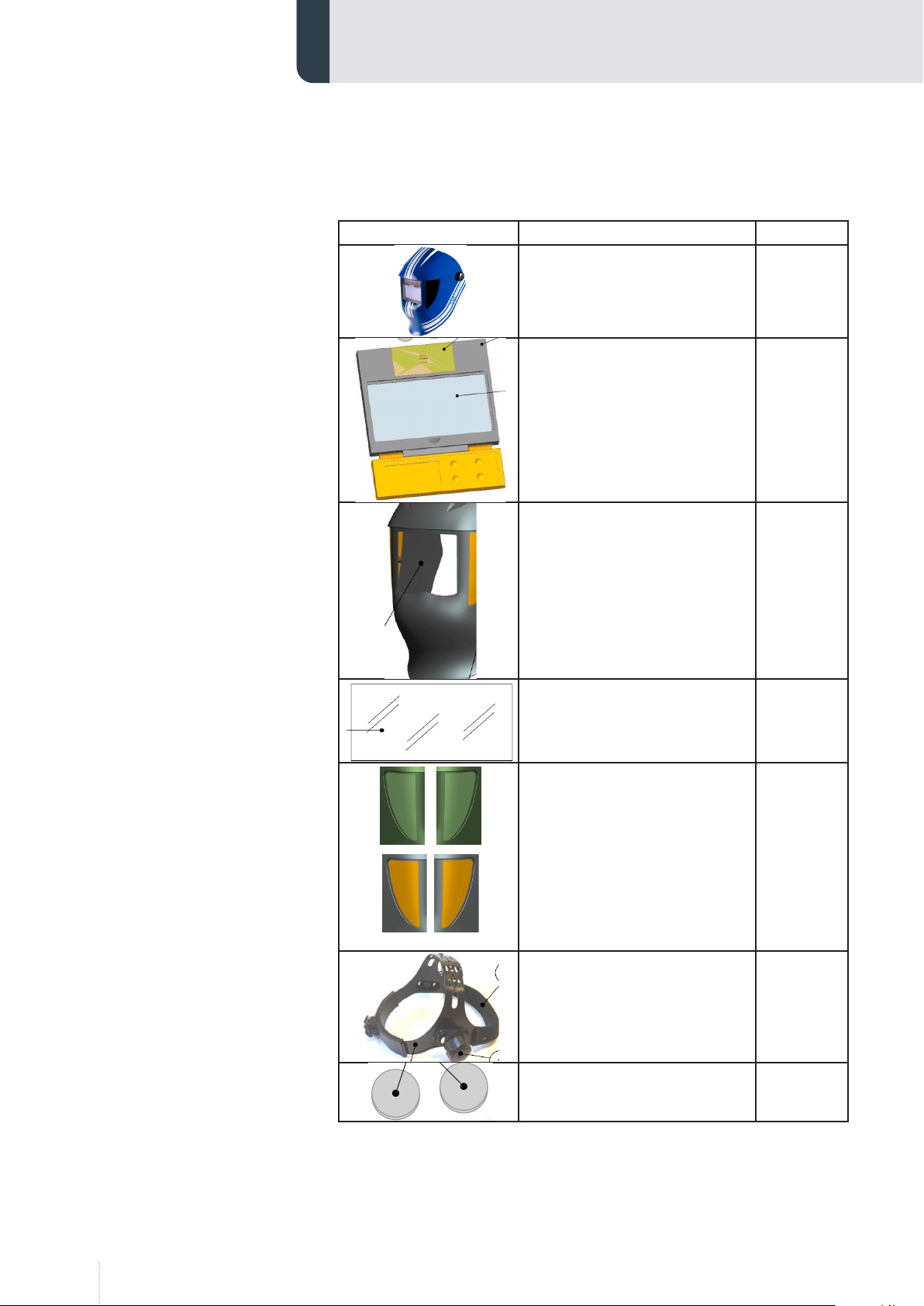
6. Spare parts
Item Designation Part No.
Welding helmet
Cloos ArcFlash 4 evo 875006200
CLOOS Arc Flash 4 evo automatic
filter cpl 875006201
CLOOS Arc Flash 4 evo protect
glass out (10pc) 875006202
CLOOS Arc Flash 4 evo protect
glass in (10pc) 875006203
orange = black
CLOOS Arc Flash 4 evo
sideglass DIN S5 l+r
CLOOS Arc Flash 4 evo
sideglass black l+r
875006204
875006205
CLOOS Arc Flash 4 evo headgear
cpl. 875006206
CLOOS Arc Flash 4 evo battery
(2pc) 875006207

15

www.cloos.de
Carl Cloos Schweisstechnik GmbH
Industriestrasse 22-38
D-35708 Haiger
Telephone +49 (0)2773 85-0
Telefax +49 (0)2773 85-275
E-Mail [email protected]
www.cloos.de
Other manuals for Arc Flash 4 evo
1
Table of contents
Popular Motorcycle Accessories manuals by other brands

Gammatronix
Gammatronix Black top Dual System installation manual

PUIG
PUIG 3758 Mounting instructions

hepco & becker
hepco & becker 6607546 01 01 Mounting instructions

GIVI
GIVI E105 Mounting instructions

Wunderkind Custom
Wunderkind Custom 106852-F15 Installation and safety manual

R&G
R&G PKS0057SI Fitting instructions


