manuals.online logo
Brands
  1. Home
  2. •
  3. Brands
  4. •
  5. LORCH
  6. •
  7. Welding System
  8. •
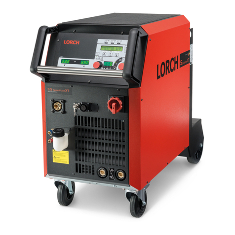
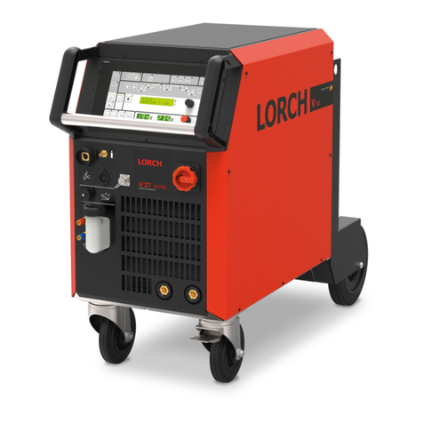
  9. LORCH MicorMIG Series User manual

LORCH MicorMIG Series User manual

Service Manual
MicorMIG
909.2130.1-10
page 2
Document no. 909.2130.1-10
Issue date: 03.11.2020
Machine elements
1 Hoisting point 10 Torch socket/digital push pull (optional)
2 Chain 11 Main switch
3 Diagnostics connection socket (internal bus) 12 Minus socket for ground cable (MIGMAG, MMA), electrode holder
(MMA), torch (TIG)
4 Inert gas hose 13 Plus socket for ground cable (MMA, TIG), electrode holder (MMA),
5 Mains cable 14 Coolant supply line and return line (optional)
6 Lock, side part, wire feed 15 Central bush
7 Hand grip 16 Coolant lling nozzle (optional)
8 Control panel 17 Interpass hose package
9 Protective cover, operating console 18 Rotary bearing
Contents
Machine........................................................................... 3
Safety precautions........................................................... 4
The MicorBoost Inverter Principle ................................... 5
Counting pins for Minit and Microt connectors............. 5
Common Functions ......................................................... 6
Pc-Board NEFI02 .......................................................... 12
Pc-Board NEFI04 .......................................................... 13
Pc-Board NEFI05 .......................................................... 14
Pc-Board NEFI07 .......................................................... 15
Pc-Board DRV03 / DRV13 ............................................ 16
Pc-Board SF02.............................................................. 18
Pc-Board DRV05 / DRV15 ............................................ 19
Pc-Board DRV07 / DRV17 ............................................ 22
Pc-Board DC01 ............................................................. 28
Pc-Board DC03 ............................................................. 29
Pc-Board DC04 ............................................................. 30
Pc-Board MAPRO04 ..................................................... 31
Pc-Board DMR-RT3 ...................................................... 32
Pc-Board DMRPP05...................................................... 33
Pc-Board SF18.............................................................. 36
Pc-board SF23 .............................................................. 38
Pc-board SF24 .............................................................. 40
Pc-board SF27 .............................................................. 41
Pc-board SF37 .............................................................. 42
Temperature monitoring................................................. 46
Monitoring bus voltage .................................................. 48
PE (Protective Earth) -Protection .................................. 49
Cooling unit.................................................................... 49
Monitoring Output Voltage ............................................. 50
Open Circuit Voltage Generator & VRD ........................ 51
Monitoring welding current ............................................ 51
Monitoring and driving the wire feed motor ................... 52
Supply Voltages............................................................. 54
Machine Conguration................................................... 55
Monitoring Primary Input Current .................................. 56
Fan Control.................................................................... 58
Mains Monitoring ........................................................... 58
LorchNet-Remote .......................................................... 59
LorchNet Connect.......................................................... 60
Reading out machine data............................................. 62
Information Messages ................................................... 64
Error codes.................................................................... 65
page 3
Machine
15
II
00
1416
7 86 9 1
5
4
3
2
1
11
12
13
10
II
00
54
3
2
1
15
14
16
11
12
13
17
10
8
9
6
18
page 4
Safety precautions
Requirement
Use and maintenance of welding and cutting machines can be dangerous. Please draw user´s attention to
follow the safety precautions to avoid injuries. Welding and cutting machines must be used appropriately
and only by qualied/trained sta󰀨. Please follow safetyregulations and use safety precautions in order to
prevent accident when working with these machines.
Only qualied workers who are knowledgeabel and have been trained to work safely with test instruments and
equipment on energized circuits shall be permitted to perform testing work on electrical circuits or equipment were
there is danger of injury from accidental contact with energized parts or improper use of the test instruments and
equipment.
Use only original spare parts
Replace immediately any components that are not in perfect condition.
Norms
IEC 60974-4 In-service inspection and testing
Testing Lorch machines according to IEC 60974-4
- it is not necessary to disconnect any components of the power unit for the test
- it is recommended to disconnect the torch at water cooled machines
- the machine has to be cleaned properly before the test
- switch to MMA mode (stick electrode) if possible
page 5
The MicorBoost Inverter Principle
A welding inverter is a electronically controlled welding power source. At conventional transformer based ma-
chines, the mains voltage with 50/60 Hz is directly switched to the welding transformer. At a welding inverter the
mains voltage is rectied rst and with electronic power switches (MOSFETs or IGBTs) chopped into a much
higher frequency, to drive the transformer. At conventional inverters this is a xed frequency (e.g. 80kHz) at
MICOR machines the frequency is variabel (up to 200kHz), because the frequency is also used for controling the
welding process. Driving the transformer, the primary side is a serial resonant circuit (primary transformer coil in
series with a capacitor) and the secondary side is a parallel resonant circuit, so that the control has an additional
inuence on the output voltage by shifting the frequency. With this principle an almost ideal output characteristic
can be realized.
Counting pins for Minit and Microt connectors
The way of reading the pin numbers on the Minit- and Microt-connectors is done always in the same way: when
looking from the top onto the connector, pin no.1 is alway on the far left, opposite to the clip.
Clip
654
32121
43
1
2
page 6
Common Functions
Gas test
- press key A14
- the gas test LED is lit
- the solenoid valve is switched on for 30 seconds
- press key A14 again to switch o󰀨 the valve manually
Fan test
When switching on the machine at the on/o󰀨 switch, the fans are activated for a short time during initialisation.
Water pump test
Basic/BasicPlus:
- press key A2 and keep it pressed for about 5 seconds (menu machine conguration)
- select menu item “CoL” with the left encoder
- with the setting “on” the water pump runs continously
- with the setting “Aut” the water cooling runs in automatic mode (factory setting)
ControlPro:
- select menu item M4 Settings
- select Menu item M4-3 Mode cooling unit
- selection “On” the water pump is running continously
- selection “Auto” the water pump runs in automatic mode (factory setting)
- press knob A49 to conrm the new selection
Front panel test
- press keys A2 and A14 at the same time
- all LEDs are on
Master reset
Basic/BasicPlus:
- switch o󰀨 the machine
- press key A2 and keep it pressed
- switch on the machine with the key pressed
- release key A2
- select parameter “rSt” with the left encoder
- press key “Save”
ControlPro:
- switch o󰀨 the machine
- press and hold menu key A50
- switch on the machine with the key pressed
- release menu key A50
- selec parameter “Masterreset” with knob A49
- press knob A49 to conrm
Since software version 2.02, the start-menu can also be accessed without switching o󰀨 the machine:
- press and hold the keys A2 and A32
- after about 3 seconds the start-menu is displayed
- select “rSt” (BasicPlus) or “Masterreset” (ControlPro)
- press key A14 “Save” (BasicPlus) or press knob A49 (ControlPro) to conrm
page 7
Front panel MicorMIG BasicPlus
A2 A14
A32
Front panel MicorMIG ControlPro
A2 A14
A50
A32
A49
page 8
Front panel MicorMIG Feeder Panel
A2 A14
Schematic
BF
µP
CAN
UART
+
1
10
2
3
6
7
5
1
10
2
3
6
7
5
MAPRO
X2
+16V
µP
CAN
13 13
99+24V
1
10
2
3
6
7
5
DMR-RT3
µP
CAN
9
X3
At compact machines the front panel is directly connected to the MAPRO. At a wire feeder MF08 the front panel is
connected to the DMR-RT3. All front panels are designed for a supply voltage range of 15V to 24V DC.
The data communication is done via CAN-bus only (pins 2 and 3 of the at ribbon cable). The serial interface
wires (UART on pins 6 and 7) are only used for programming the microprocessor (front panel software update).
page 9
Synergic selection panel
Since week 24 of 2018 new welding programs have been added to the new software version 2.12 including new
materials and 0.9mm wire. Thus the synergic selection panel were changed also.
wire feeder power source
Schematic synergic selection panel
2
3
4
5
6
1
1
keys
LEDs
Since May 2017 there are locking clips available to keep the at ribbon cables xed at the front panels and pre-
vent a disconnection from the at ribbon socket at the PCBs.
773.0020.2 773.0021.2
page 10
Picture pc-board BF07 (Basic Plus wire feeder)
X301
X401
X201
X701
Since week 10 in 2015 the front panels of the wire feeder are equipped with longer at ribbon cables. With this it
is possible to use the wire feeder horizontally in a lying way and turn the front panel by 90°.
Picture pc-board SF17
The pc-board SF17 is used for illuminating the interior of the MF08 wire feeder and is connected to the front panel
pc-board (connector X701).
page 11
Picture pc-board BF11 (ControlPro power source)
X301
X201
X401
Overview changes front panels
Some front panels had been exchanged by versions with bigger memory.
Since week 51 from 2017 the version “Pulse” was added.
front panel designation
(old)
part no. designation
(new)
part no. version
pulse
part no. useage
FP01 BF05 653.0062.5 BF25 653.0083.5
wire feederBasic BF06 653.0048.5 BF26 653.0079.5
Basic Plus BF07 653.0049.5 BF27 653.0080.5 BF27 653.0107.5
Basic BF09 653.0051.5 BF29 653.0081.5 power source
Basic Plus BF10 653.0052.5 BF30 653.0082.5 BF30 653.0109.5
page 12
Pc-Board NEFI02
The pc-board NEFI02 is the mains lter board of the MicorMIG 300 and 350.
Since week 49 2015 the varistors at the mains input had been replaced by types with higher voltage (S20K620).
Functions
- mains lter
- mains detection
- safeguarding control transformer (2 x 4.0A, 500V, slow)
Picture pc-board NEFI02
X1
X2
LP2
LP1
LP3
LP7
LP5
LP6
LP14
PE
LP15 (PE)
Schematic
2
1
3
LP15 PE
6
5
7
4
8
11
12
L2
L1
L3
14
U
+Uz
-Uz
X1-3
X1-1
X2-3
X2-1
SI1
SI2
mains
page 13
Pc-Board NEFI04
The pc-board NEFI04 is the mains lter board of the MicorMIG 400.
Since week 49 2015 the varistors at the mains input had been replaced by types with higher voltage (S20K620).
Functions
- mains lter
- mains detection
- safeguarding control transformer (2 x 4.0A, 500V, slow)
Picture pc-board NEFI04
X1
X2
LP2
LP1
LP3
LP7
LP5
LP6
LP14
PE
LP15 (PE)
Schematic
2
1
3
LP15 PE
6
5
7
4
8
11
12
L2
L1
L3
14
U
+Uz
-Uz
X1-3
X1-1
X2-3
X2-1
SI1
SI2
mains
page 14
Pc-Board NEFI05
The pc-board NEFI05 is the mains lter board of the MicorMIG 500.
Since week 49 2015 the varistors at the mains input had been replaced by types with higher voltage (S20K620).
Functions
- mains lter
- mains detection
- safeguarding control transformer (2 x 4.0A, 500V, slow)
- power-up function
Picture pc-board NEFI05
X2 X1
LP2LP1 LP3
PE
Schematic
2
1
3
LP15 PE
6
5
7
4
8
11
12
L2
L1
L3
14
U
+Uz
-Uz
X1-3
X1-1
X2-3
X2-1
SI1
SI2
24
28
26
25
27 RE1
RE2
R7R8
9
10
RE1 RE2
mains
page 15
Pc-Board NEFI07
The pc-board NEFI07 is the mains lter board of the MIcorMIG 400 MV and 500 MV.
Functions
- mains lter
- mains detection
- safeguarding control transformer (2 x 4.0A, 500V, slow)
- power-up function
Picture pc-board NEFI07
A
B
X4
X6
X5
X3
X1
X2
Schematic
PM1
B
+
-
A
DRV
PM2
B
+
-
A
X6
X3
X4
X5
Q2
Q2
Q2
6
5
4
3
2
1
LP3
LP4
LP5
LP6
LP7
LP8
12V
RE1+2
RE3+4
PE
X1-1
X1-2
X2-3
X2-1
LP2
Q2
10
12
9
11
400
230
0
19
42
11
NEFI07
LP10
U
Si1
Si2
page 16
Pc-Board DRV03 / DRV13
The pc-board DRV03 is the primary driver board of the MicorMIG 300 and 350.
Since week18 2017 the DRV03 was replaced by the DRV13. For details see page 27.
Functions
- primary driving of the transformer
- capture primary input current
- measuring temperatures
- generating internal supply voltages
- driving fans
- switching power-up relays
- PE monitoring
- coding power unit
- monitoring mains voltage
- monitoring bus voltage
LEDs
LED state designation
1 (red) blinking (1 Hz) normal operation
blinking (3 Hz) when switching o󰀨 the machine (no mains voltage present)
lit weak DSP not programmed
o󰀨 3.3V supply voltage is missing
Measuring points
designation measuring
point
result
bus voltage
(from rectier)
X17-4
X17-1
+Uz
-Uz
ca. +580 V DC
bus voltage
(at the power modules)
D27
D28
+Uz
-Uz
ca. +580 V DC
supply voltage +24V X6-2, X7-2, X11-2
X6-1, X7-1, X11-1
+
-
+24V DC
supply voltage +16V X2-1
X2-2
+
-
+16V DC
supply voltage +60V X1-5
X1-6
+
-
+60V DC
Measuring points bus voltage (power modules)
+Uz -Uz
page 17
Picture pc-board DRV13
X1 X6 X7 X11 X5 X8 X9
X12
X13
X15
X14
X4
X2
X3
TR4
TR3
TR2
TR1
X17
LED1
BA+ -
temp.sens.
DMR
MAPRO
MAPRO
CAN CAN
NEFI
234 1
R75 R78
D28
D27
SI3 SI1 SI4
+Uz -Uz
X19
SI2
DIP1
aux. transf.
sec. fan
aux. transf.
prim.
PE-prot.
Inside diagram power module
ϑ
20
19
18
17
16 15 14 13
12 11
10
9
8
7
6
5
4
3
2
1
20
19
18
17 16 15
14
13 12 11 10
9
8
7
6
54321
page 18
Schematic
X17
-Uz
+Uz
1
2
3
4
-
B
A
+
RE1
RE2
TM2
TM1
TR3
TR4
TR2
X4
1
2
3
4
5
SF02
Ip
TR1
DRV03
C62 C67
C61 C66
R75
R78
D27
D28
19V
42V
X5-2
X5-1
X5-4
X5-3
Si1
Si3
+24V
+60V
+24Vext.
Si2
+16V
11V X13-1
X13-3 Si4 +16Vprim.
+3,3V
-Uz
+5V
+3,3V
Fuses DRV13
fuse value
Si1 (24V) 6.3 A
Si2 (24V ext.) 1.5 A
Si3 (60V) 6.3 A
Si4 (16V) 0.63 A
Pc-Board SF02
The pc-board SF02 contains the primary resonance capacitors and is only used together with the pc-board
DRV03.
Functions
- wiring primary transformer wires
- connecting resonance capacitors
Picture pc-board SF02
X4
4
5
2
3
1
page 19
Pc-Board DRV05 / DRV15
The pc-board DRV05 is the primary driver board of the MicorMIG 400.
Since week18 2017 the DRV05 was replaced by the DRV15. For details see page 27.
Functions
- primary driving of the transformer
- capture primary input current
- measuring temperatures
- generating internal supply voltages
- driving fans
- switching power-up relays
- PE monitoring
- coding power unit
- monitoring mains voltage
- monitoring bus voltage
LEDs
LED state designation
1 (red) blinking (1 Hz) normal operation
blinking (3 Hz) when switching o󰀨 the machine (no mains voltage present)
lit weak DSP not programmed
o󰀨 3.3V supply voltage is missing
Measuring points
designation measuring
point
result
bus voltage
(from rectier)
X17-4
X17-1
+Uz
-Uz
ca. +580 V DC
bus voltage
(at the power modules)
T13
T14
+Uz
-Uz
ca. +580 V DC
supply voltage +24V X6-2, X7-2, X11-2
X6-1, X7-1, X11-1
+
-
+24V DC
supply voltage +16V (X19) X2-1
(X19) X2-2
+
-
+16V DC
supply voltage +16V (primary) X14-2
X17-1 / T14
+
-Uz
+16V DC
supply voltage +60V X1-5
X1-6
+
-
+60V DC
page 20
Picture pc-board DRV15
X2
3
12
4
LED1
X17
B
A
+
-
R78
D28 D27
R75
X8
X16
X12
X9
X13
X15
X14
X5
X7X11
X1 X6
X3
X4
Si4
Si2 Si3 Si1
T16
T17
T18
T19
X19
T12
T13
+Uz
T14
-Uz
T15
DIP1
Uz/2
Uz/2
Change from MOSFET to IGBT (DRV05)
Since the 10th of July 2015, since serial number 4062-2528-0021-6 only IGBTs are used for the MicorMIG 400.
type old new
T12 - T15 MOSFET (711.2614.0) IGBT (711.0530.0)
T16 - T19 IGBT (711.2616.0) IGBT (711.0530.0)

This manual suits for next models

6

Other LORCH Welding System manuals

LORCH V Series User manual

LORCH

LORCH V Series User manual

LORCH T BasicPlus Series User manual

LORCH

LORCH T BasicPlus Series User manual

LORCH EC-Clean 1000R User manual

LORCH

LORCH EC-Clean 1000R User manual

LORCH a-LTG/i-LTG User manual

LORCH

LORCH a-LTG/i-LTG User manual

LORCH M-Pro Performance Series User manual

LORCH

LORCH M-Pro Performance Series User manual

LORCH X Series User manual

LORCH

LORCH X Series User manual

LORCH MX 350 EU User manual

LORCH

LORCH MX 350 EU User manual

LORCH HandyTIG 180 DC Basic Plus User manual

LORCH

LORCH HandyTIG 180 DC Basic Plus User manual

LORCH M-Pro BasicPlus User manual

LORCH

LORCH M-Pro BasicPlus User manual

LORCH MicorStick 160 User manual

LORCH

LORCH MicorStick 160 User manual

LORCH M-Pro BasicPlus User manual

LORCH

LORCH M-Pro BasicPlus User manual

LORCH ControlPro T-Series User manual

LORCH

LORCH ControlPro T-Series User manual

LORCH MicorStick User manual

LORCH

LORCH MicorStick User manual

LORCH Saprom S User manual

LORCH

LORCH Saprom S User manual

LORCH MicorStick 200 ControlPro User manual

LORCH

LORCH MicorStick 200 ControlPro User manual

LORCH M 2020 User manual

LORCH

LORCH M 2020 User manual

LORCH S-Pulse User manual

LORCH

LORCH S-Pulse User manual

Popular Welding System manuals by other brands

Leister GEOSTAR G5 LQS operating instructions

Leister

Leister GEOSTAR G5 LQS operating instructions

Kjellberg PerCut 200 Short instruction manual

Kjellberg

Kjellberg PerCut 200 Short instruction manual

Fimer KRONOS 500 dual-pulse instruction manual

Fimer

Fimer KRONOS 500 dual-pulse instruction manual

Lincoln Electric Power-Arc 5500 Operator's manual

Lincoln Electric

Lincoln Electric Power-Arc 5500 Operator's manual

Miller Electric Subarc DC 650 owner's manual

Miller Electric

Miller Electric Subarc DC 650 owner's manual

Gude MIG 175 ZD/A Translation of original operating instructions

Gude

Gude MIG 175 ZD/A Translation of original operating instructions

Ter Welding Multi 250 instruction manual

Ter Welding

Ter Welding Multi 250 instruction manual

Miller Welding Safety quick-guide

Miller

Miller Welding Safety quick-guide

Demtech Pro-Wedge 3XL Operator's manual

Demtech

Demtech Pro-Wedge 3XL Operator's manual

Chicago Electric 61205 Owner's manual & safety instructions

Chicago Electric

Chicago Electric 61205 Owner's manual & safety instructions

Cebora POWER ROD 131 instruction manual

Cebora

Cebora POWER ROD 131 instruction manual

Eastwood ARC 80 20295 Assembly & operating instructions

Eastwood

Eastwood ARC 80 20295 Assembly & operating instructions

Lincoln Electric Idealarc R3R-500-I Technical specifications

Lincoln Electric

Lincoln Electric Idealarc R3R-500-I Technical specifications

Migatronic RALLY MIG 161i user guide

Migatronic

Migatronic RALLY MIG 161i user guide

EWM L2.00 DC Expert 3.0 TIG operating instructions

EWM

EWM L2.00 DC Expert 3.0 TIG operating instructions

GYS Gyspot 39.02 user manual

GYS

GYS Gyspot 39.02 user manual

Magnum 100SG SPOOL GUN Installation

Magnum

Magnum 100SG SPOOL GUN Installation

Miller Electric XMC 4000 owner's manual

Miller Electric

Miller Electric XMC 4000 owner's manual

manuals.online logo
manuals.online logoBrands
  • About & Mission
  • Contact us
  • Privacy Policy
  • Terms and Conditions

Copyright 2025 Manuals.Online. All Rights Reserved.