Cloud RH-8 User manual

RH-8
Installation Guide V6.0
Cloud Electronics Limited
140 Staniforth Road, Sheffield, S9 3HF England
Tel +44 (0) 114 244 7051
Fax +44 (0) 114 242 5462
E-mail [email protected]
Web site http://www.cloud.co.uk

RH-8: Installation Guide 1
RH-8
Installation Guide
Contents
Section Page
1 Introduction ..............................................................................2
2 Mechanical Installation............................................................2
3 Electrical Installation ...............................................................3
Wiring an RH-8 to a Pump/Sub Station 16-R .............................3
Hard Wiring an RH-8 to a Pump/Sub Station 16-R ....................4
4 Controlling a Pump Station 16-R Line Level Output with
an RH-8......................................................................................4
5 Connecting Headphones to an RH-8 ......................................4
6 Wiring an RH-8 to a Pump Station 16 .....................................4
7 Hard Wiring an RH-8 to a Pump Station 16 ............................5
15-05-02 V6

2 RH-8: Installation Guide
1 Introduction
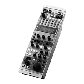
The Cloud RH-8 is a remote control module designed to be used in
conjunction with the Cloud headphone distribution processors. The RH-8
remote control panel has facilities that allow a user to select the music level
and music source while monitoring the signal through stereo headphones.
2 Mechanical installation
An RH-8 can be strapped to framework of exercise machinery by fixing the
supplied nylon support brackets to the back of the RH-8 and then use the
provided nylon ties to wrap around the frame. See the illustrations below:
FIT
BRACKET
HERE
FIT
BRACKET
HERE
FIT
BRACKET
HERE
FIT
BRACKET
HERE
The nylon brackets are held in place by removable ‘snap rivets’. Locate the bracket in the
recess on the base of the RH-8, place the rivet through the mounting hole and press the
plunger until resistance is felt. Loop the nylon ties through the slots in the brackets and fasten
the RH-8 to the framework. If the surface of the framework is smooth, it may be beneficial to
wrap the frame with self-amalgamating electrical tape prior to fitting the nylon ties.
When mounted to framework the RH-8 should be positioned at 45o(see left hand diagram
below), ideally the RH-8 should also be positioned to one side of the user instead of directly in
front (See right hand diagram below)
Two mounting holes are provided in the base of the RH-8 to provide the means to fix it onto a
flat surface. Remove the two screws that secure the front panel to the rear and lift off the front
cover. Locate the two fixing holes positioned above the data socket and to the right of the
headphone socket. Two self-tapping screws are provided for fixing purposes. If you propose to
use the data socket, it will be necessary to cut a rectangular hole in the mounting surface to
clear the data plug. Alternatively, the RH-8 can be hard wired by feeding the cable through the
7mm hole in the rear of the RH-8. When refitting the front cover, care must be taken to ensure
that the screws are not over tightened otherwise the plastic moulding may be damaged.
15-05-02 V6

RH-8: Installation Guide 3
3 Electrical Installation
Each RH-8 is fitted with an RJ45 data socket and supplied with a
3m patch cord. We suggest that a separate RJ45 floor socket is
located adjacent to every RH-8 control panel location and that the
supplied patch lead is used to link the RH-8 to the floor socket; this
approach simplifies maintenance. Each individual floor socket
should be wired ‘pin to pin’ directly to the equipment rack using
unscreened ‘Category 5’ cable (4 pair CAT 5). The total cable
length from an RH-8 to the rack should not exceed 100m (328ft).
Wiring Information: RH-8 (RJ45) to a Pump/Sub Station 16-R
RH-8 (RJ45) Pump/Sub Station 16-R CAT 5*
Pin 1 Pin 1 White/Orange
Pin 2 Pin 2 Orange/White
Pin 3 Pin 3 White/Green
Pin 4 Pin 4 Blue/White
Pin 5 Pin 5 White/Blue
Pin 6 Pin 6 Green/White
Pin 7 Pin 7 White/Brown
Pin 8 Pin 8 Brown/White
*The CAT 5 colour is described as the dominant colour first with the tracer second.
The RJ45 plug is a compact 8-pole
connector primarily designed for CAT5
cable. The pin out for the RJ45 plug and
socket is shown to the right:
Special tools are available making termination both easy and quick. Instructions for termination
of an RJ45 plug are as follows:
1) Strip approximately 1” of outer sheath from the cable.
2) Remove extraneous material such as plastic wrap or foil screen from the 8 exposed cores
but do not strip their sheaths.
3) Cut the 8 exposed cores down so that when the cable is inserted into the RJ-45 the outer
core can be held by the plugs cable retention system.
4) Insert the 8 cores into the RJ-45 plug fully making sure that they are all correctly arranged.
(Information for the correct arrangement of cores for the RH-8 can be found on page 3&4)
5) Place the plug/cable assembly into the assembly tool and operate the mechanism.
6) You should now have a firmly connected plug/cable assembly that is ready for installation.
Note: The above instructions are for guidance only; always follow the instructions supplied with
the assembly tool.
When mounted directly on to a wall or perhaps the bulkhead of an exercise machine the RJ45
socket of the RH-8 may not be accessible. In this scenario it may be preferable to hard wire a
cable directly to the RH-8 using its internal screw terminals. When using the screw terminals
the use of a separate RJ45 floor socket adjacent to the RH-8 is still suggested.
Please note: The Pump Station 16 and Sub Station 8 have been discontinued as of March
2002 and November 2001 respectively, information regarding wiring an RH-8 to either of these
units can be found on pages 4 & 5.
15-05-02 V6

4 RH-8: Installation Guide
Hard Wiring an RH-8 to a Pump/Sub Station 16-R
Wiring Information: RH-8 (Screw Terminal) to a Sub Station 16/RJ45 Floor Socket
RH-8 (Screw Terminal) Sub Station 16 (RJ45) or RJ45 Floor Socket CAT 5*
Pin 1 Pin 8 Brown/White
Pin 2 Pin 7 White/Brown
Pin 3 Pin 6 Green/White
Pin 4 Pin 5 White/Blue
Pin 5 Pin 4 Blue/White
Pin 6 Pin 3 White/Green
Pin 7 Pin 2 Orange/White
Pin 8 Pin 1 White/Orange
*The CAT 5 colour is described as the dominant colour first with the tracer second.
4 Controlling a Pump Station Line Level Output with an RH-8
Channel 16 on a Pump Station is fitted with a mono balanced line level output that can be used
to feed a signal to a general PA system, perhaps for background music purposes. When this
facility is used, an RH-8 wired to channel 16 should be used to control the music signal level
and the music source selection. When an RH-8 is used for this purpose, it is not necessary to
have any headphones connected.
5 Connecting Headphones to an RH-8
The Cloud RH-8 is fitted with a 3.5mm stereo jack socket for the connection of a pair of stereo
headphones. For satisfactory performance we recommend the use of headphones with a 32Ω
impedance. The whole system is optimised for use with Cloud CP-32 headphones.
6 Wiring an RH-8 to a Pump Station 16 or Sub Station 8
Wiring Information: RH-8 (RJ45) to a Pump Station 16 or Sub Station 8
RH-8 (RJ45) Pump Station 16 / Sub Station 8 (Screw Terminal) CAT 5*
Pin 1 Pin 8 White/Orange
Pin 2 Pin 7 Orange/White
Pin 3 Pin 6 White/Green
Pin 4 Pin 5 Blue/White
Pin 5 Pin 4 White/Blue
Pin 6 Pin 3 Green/White
Pin 7 Pin 2 White/Brown
Pin 8 Pin 1 Brown/White
*The CAT 5 colour is described as the dominant colour first with the tracer second.
15-05-02 V6

RH-8: Installation Guide 5
15-05-02 V6
7 Hard Wiring an RH-8 to a Pump Station 16 or Sub Station 8
Wiring Information: RH-8 (Screw Terminal) to a Pump Station 16
RH-8 (Screw Terminal) Pump Station 16 (Screw Terminal) CAT 5*
Pin 1 Pin 1 Brown/White
Pin 2 Pin 2 White/Brown
Pin 3 Pin 3 Green/White
Pin 4 Pin 4 White/Blue
Pin 5 Pin 5 Blue/White
Pin 6 Pin 6 White/Green
Pin 7 Pin 7 Orange/White
Pin 8 Pin 8 White/Orange
*The CAT 5 colour is described as the dominant colour first with the tracer second.
Should you need any further help please do not hesitate to contact our technical staff
(Contact details are on the front cover)
Table of contents
