CMA Dishmachines AK User manual

$//$8720$7,&
&2))((0$.(5
(QJOLVK
7(&+1,&$
/
0$18$/
5
All manuals and user guides at all-guides.com
all-guides.com

All manuals and user guides at all-guides.com

THIS MACHINE IS MADE IN COMPLIANCE WITH THE REQUIREMENTS
OF THE FOLLOWING CEE DIRECTIVES
89/392/CEE - 89/336/CEE - 73/23/CEE
All manuals and user guides at all-guides.com

ENGLISH 4
TECHNICAL MANUAL
INTRODUCTION
The manufacturer reserves the right to make product improvements. It guarantees that this manual reflects the technological
state at the time the machine was sold.
We are open to suggestions from technicians on any way that might improve the product and the manual.
GENERAL WARNINGS
lOnce the packaging has been removed make certain the appliance is sound; if you have any doubts, check the fault
and contact the retailer or manufacturer directly.
lPackaging must not be left where children can reach it as it is a potential ha ard source.
lThe appliance must be installed in compliance with the safety standards in force in the country of use.
lThis appliance is completely safe only when it is connected to an effective earthing system that complies with the
safety standards. Make sure that the mains power is sufficient for the energy required for the machine.
lIt is unadvisable to use extension leads or electrical adaptors for multiple sockets. If it is essential to use them, use
only single adaptors or leads that comply with the current safety standards. Never exceed the capacity indicated on the
adaptor or leads, or the maximum power indicated on the adaptor.
lThis appliance should only be used for what it has been designed for. Any other use is considered improper and
consequently dangerous. The manufacturer cannot be held responsible for any damages caused due to an erroneous
or irrational use. The technician must remind the user about the safety standards to ensure correct operation of the
appliance.
lThe use of an electrical appliance must be subject to the safety standards.
lIf the customer decides he is not going to use the appliance for a long time, he must disconnect the power cable from
the mains and empty it the water contained therein.
lTo guarantee that the coffee-maker works properly and efficiently it is essential to follow the manufacturers instructions,
carrying out periodical maintenance and a check of all the safety devices.
lAlways make sure that hands, or other parts of the body, never come within the range of the coffee dispensing spouts
or those of steam and hot water since these can scald.
lThe repair technician must inform the retailer or manufacturer promptly of any problems when installing or using the
appliance.
All manuals and user guides at all-guides.com

ENGLISH5
TECHNICAL MANUAL
Summary
1. GENERAL DESCRIPTION .....................................................................................................................................6
2. TECHNICAL SPECIFICATIONS ..............................................................................................................................7
3. DESCRIPTION OF THE INTERNAL COMPONENTS ..............................................................................................7
4. PREPARING THE MACHINE .................................................................................................................................8
4.1 Unpacking .........................................................................................................................................................8
4.2 Preparing the grinder-dosers ............................................................................................................................8
4.3 Positioning the machine ....................................................................................................................................8
5. INSTALLAING AND MAINTENANCE ......................................................................................................................9
5.1 Hydraulic connection .........................................................................................................................................9
5.2 aintenance and cleaning ................................................................................................................................ 9
5.3 Electrical connection ...................................................................................................................................... 10
5.4 Switching the machine on and adjusting the pump ....................................................................................... 10
6. PROGRAMMING ................................................................................................................................................. 11
6.1 Programming ENU ....................................................................................................................................... 11
6.2 GRINDING programming .............................................................................................................................. 12
6.3 ADDED WATER programming ...................................................................................................................... 14
6.4 COFFEE, ILK, TEA DOSES programming .................................................................................................. 15
6.5 CLOCK programming .................................................................................................................................... 16
6.6 Carrying out the INPUT TEST ........................................................................................................................ 17
6.7 Checking CO PONENT functionality ............................................................................................................ 18
6.8 INFO reading .................................................................................................................................................. 20
7. CONFIGURATION ................................................................................................................................................ 22
7.1 Preparing the machine ................................................................................................................................... 22
7.2 Configurating the machine ............................................................................................................................. 23
7.3 achine SIGNALS and WARNINGS ............................................................................................................. 25
7.4 achine CYCLE counting .............................................................................................................................. 26
7.5 Configuration of the servicing warning ........................................................................................................... 27
7.6 Button configuration........................................................................................................................................ 27
8. MACHINE COMPONENTS.................................................................................................................................. 28
8.1 Boiler............................................................................................................................................................... 28
8.2 Heat exchanger .............................................................................................................................................. 28
8.3 Automatic Water Inlet ..................................................................................................................................... 28
8.4 Volumetric doser ............................................................................................................................................ 28
8.5 Dispensing unit ............................................................................................................................................... 29
8.6 Checking pressure ......................................................................................................................................... 30
8.7 Anti-flooding device ........................................................................................................................................ 30
8.8 Valve unit ........................................................................................................................................................ 30
8.9 Pump system .................................................................................................................................................. 31
8.10 Cappuccino-maker ........................................................................................................................................ 31
9. ELECTRONIC SYSTEM ....................................................................................................................................... 32
10. TROUBLESHOOTING .......................................................................................................................................... 33
10.1 Indications on the display............................................................................................................................... 33
10.2 Functional failures and problems .................................................................................................................. 36
11. WIRING DIAGRAMS ............................................................................................................................................ 39
11.1 OTHER BOARD connector diagram ........................................................................................................... 39
11.2 HIGH VOLTAGE electrical circuit .................................................................................................................... 40
11.3 LOW VOLTAGE electrical circuit ..................................................................................................................... 41
11.4 OTORS and SOLENOID VALVES electrical circuit ..................................................................................... 42
11.5 ELECTRONIC CARDS electrical circuit ......................................................................................................... 43
11.6 LED electronic diagram.................................................................................................................................. 44
12. HYDRAULIC DIAGRAMS ..................................................................................................................................... 45
12.1 General hydraulic diagram ............................................................................................................................ 45
12.2 Cappuccino-maker hydraulic diagram .......................................................................................................... 46
12.3 Added water hydraulic diagram ..................................................................................................................... 47
All manuals and user guides at all-guides.com

ENGLISH 6
TECHNICAL MANUAL
1. GENERAL DESCRIPTION
1. Opening for decaffeinated coffee/Opening for washing tab
2. Grinder-doser hopper
3. Opening for washing tab
4. Machine door
5. Programming key
6. Steam dispensing knob
7. Steam dispensing spout
8. Hot water dispensing pipe
9. Pressure gauge
10. Grouts box
11. Coffee dispensing spout
12. Main switch for switching on machine
13. Feet
14. Functions control touch pad
15. Touch pad panel display
16. Cappuccino-maker
model AK
model AKC
All manuals and user guides at all-guides.com
all-guides.com

ENGLISH7
TECHNICAL MANUAL
2. TECHNICAL SPECIFICATIONS
egatlovylppuSV004/042/032
tupnilatoT W0014
)A81(
gnitaehrelioB
rewoptnemele
W002
)A21(
resod-rednirG
rewoprotom
2xW053
)A5,1(
rotompmuP
rewop
W062
)A2,1(
gnitaehtinU
rewoptnemele
2xW051
)A8,0(
ylppus/remrofsnarT
rewop
W001
)A5,0(
lortnoc/sevlavdioneloS
rewopstinu
W001
)A5,0(
yticapacrelioBsertil
gnikrowrelioB
erusserp rab2.1÷1
foerusserP
deilppusretaw rab5÷0
foerusserP
eeffocdesnepsid rab9÷8
evlavytefaS
noitarbilac rab2
)L(htdiWmc5
)P(htpeDmc45
)H(thgieHmc38
thgieWgk49
3. DESCRIPTION OF THE INTERNAL
COMPONENTS
1. Left dispensing unit
2. Left grinder-doser
3. Right grinder-doser
4. Right dispensing unit
5. Volumetric doser
6. Pressure gauge
7. Motor pump
8. Drainage trough
9. Electronic control boards
10. Main switch
11. Boiler
12. Boiler heating element
13. Pressure switch
L
P
H
All manuals and user guides at all-guides.com

ENGLISH 8
TECHNICAL MANUAL
4. PREPARING THE MACHINE
4.1 Unpacking
Proceed as follows to unpack the machine correctly:
1) Cut the straps around the packaging.
2) Pull the box off upwards.
3) Position the machine on the worktop.
4.3 Positioning the machine
There must be plenty of room for the appliance and for
using it correctly.
Prepare the place where the machine is to stand which
must be able to hold support its weight.
It is important that all the terminals of the connections to
the electricity mains and to the water mains are easy to reach
and in the immediate vicinity of the machine.
4.2 Preparing the grinder-dosers
Fit the coffee hoppers in place on the two grinder-dosers.
attention
For the machine to work properly it must stand on
a perfectly level surface.
Any corrections needed to level the machine can
be done by adjusting the feet.
We recommend keeping the packaging until the guarantee period
has expired.
information
All manuals and user guides at all-guides.com

ENGLISH9
TECHNICAL MANUAL
5. INSTALLING a d MAINTENANCE
5.1 Hydraulic connection
The softener provided with the coffee-maker has been designed to function with a working pressure ranging between 1
and 9 bar. It must only be supplied with cold drinking water.
When connecting to the water mains, install a cock between the machine and the mains so as to be able to interrupt
the supply of water to the appliance.
To stop the water from free ing, install the softener in a room where the temperature is higher than 0°C.
Before connecting the pipes remove any rubber plugs from the softener cock couplings. To connect proceed as follows:
When plumbing the coffee maker do not use iron or
galvanised iron fittings because, with the passing of
time, these materials can produce dangerous
oxidations and seriously damage the machine.
attention
1) connect the water mains (1) to the softener inlet (2)
using the flexible pipe provided;
2) rinse the softener resins checking that the water, that
is initially yellow, becomes a clear colour;
3) connect the softener outlet (3) to the machine (4);
4) connect the machine drainage trough (5) to the drain
(6) using the specific pipe provided, taking care to avoid
sharp bends or throttlings and keeping it slanted
enough for the waste water to drain away;
5) the drain (6) must be connected to an inspectionable
trap (7) that can be cleaned regularly to prevent the
reflux of bad smells.
5.2 Maintenance and cleaning
To make it easier to service and clean the inside
of the machine you can remove the various parts of
the external casing.
From the front, in particular, you can access the
inside of the machine by opening the doors that cover
the unit and push button panel.
attention
To avoid damaging the outer casing, valves and cocks, install the softener where it is protected against accidental knocks.
All manuals and user guides at all-guides.com

ENGLISH 10
TECHNICAL MANUAL
5.4 S itching the machine on and adjusting the pump
Switch the machine on as explained in the user manual.
Effect several automatic washing cycles and check the correct working
pressure on the gauge (8 - 9 bar).
If necessary, calibrate pressure by means of the by-pass adjustment
screw (1) on the pump.
5.3 Electrical connection
lConnect the cable leading from the machine to the electricity mains;
lInstall a circuit breaker (1). THREE-PHASE 400V
+ NEUTRAL
+ EARTH
C
BL
GV
NE
NE
MA
SINGLE-PHASE 230V
+ EARTH D
NE
BL
GV
NE
MA
THREE-PHASE 230
+ EARTH
BL
GV
NE
NE
MA
1
1
F
C
C
F
F
LEGEND
MA Brown
Ne Black
BL Blue
GV Yellow-Green
CMachine cable
F Electricity mains
R-S-T Phase
DPhase
NNeutral
Earth
Effect the electrical connections with the mains voltage
disconnected.
attention
All manuals and user guides at all-guides.com

ENGLISH11
TECHNICAL MANUAL
6. PROGRAMMING
PLEASE SELECT!
t=XXX YY:YY:YY
To enter programming, keep the MODE key pressed
for about 4 seconds
GRIND PROGRAMM.
To enable programming turn the
programming key clockwise.
ADD H2O PROGRAMM
Press the MODE key:
COFFEE, MILK DOSES ETC. Progr.
COFFEE DOSE PROG
Press the MODE key: ADDED WATER Progr. (optional)
Press the MODE key: CLOCK Progr.
CLOCK PROGRAMM
Press the MODE key: Test input: check PUSH
BUTTONS and MICROSWITCHES
test iNput
Press the MODE key:
check of the INTERNAL COMPONENTS
DIAGNOSTICS
Press the MODE key: EXIT the Programming function
PLEASE SELECT!
t=XXX YY:YY:YY
PLEASE SELECT!
t=XXX YY:YY:YY
To exit programming, turn the programming key
counter clockwise
Press the MODE key views WORK DONE (optional)
INFO READING
6.1 Programming MENU
see p r. 6.2
see p r. 6.3
see p r. 6.4
see p r. 6.5
see p r. 6.6
see p r. 6.7
see p r. 6.8
All manuals and user guides at all-guides.com
all-guides.com

ENGLISH 12
TECHNICAL MANUAL
is the grinding time (sec.) for one cup of espresso coffee
Alter the grinding time by pressing the arrow keys
To exit programming, press MODE a few times until the
script PLEASE SELECT! in seen
Press the ENTER key
GRIND PROGRAMM
GRIND PROGRAMM
GT 1ESP.GR1 =
GRIND PROGRAMM
GT 1esp.GR1 =
PLEASE SELECT!
t=XXX YY:YY:YY
GRIND PROGRAMM
GT 2ESP.GR1 =
RECOMMENDED: single = 2.5 double = 3.5
prei fus. PROGRAMM
PI 1ESP GR1 = ,
prei fus. PROGRAMM
PI 1ESP GR1 = ,
prei fus. PROGRAMM
PI 2ESP GR1 = ,
PLEASE SELECT!
t=XXX YY:YY:YY
6.2 Programming GRINDING
6.2.1 GRINDING TIME
6.2.2 PREINFUSION TIME
Press ENTER to confirm and carry on programming the
other selections
Press the ENTER key
Alter the preinfusion time by pressing the arrow keys
is the preinfusion time (sec.) for one cup of espresso coffee
RECOMMENDED: maximum time = 2.0
Press ENTER to confirm and carry on programming the
other selections
To exit programming, press MODE a few times until the
script PLEASE SELECT! in seen
All manuals and user guides at all-guides.com

ENGLISH13
TECHNICAL MANUAL
progRAMMING
N. GROUNDS =
PROGRAMMING
N. GROUNDS =
indicates the number of grants/spent coffee tabs in the
drawer which vary by intervals of 10
Press the ENTER key
Alter the number of grouts pressing the arrow keys
RECOMMENDED: max. number of coffee grouts = 70
Press ENTER to confirm
progRAMMING
N. GROUNDS =
PLEASE SELECT!
t=XXX YY:YY:YY
progRAMMING
TEMP. GR1 NN
progRAMMING
TEMP. GR1 ,
is the temperature (°C) of the dispensing unit
Press the ENTER key
Change the temperature by pressing the arrow keys
RECOMMENDED: Minimum = 80°C Maximum = 90°C
progRAMMING
TEMP. GR2 NN
progRAMMING
TEMP. GR2 ,
Press ENTER to confirm and carry on programming unit 2
PLEASE SELECT!
t=XXX YY:YY:YY
6.2.3 TEMPERATURE of th DISPENSING UNITS
6.2.4 NUMBER of COFFEE GROUTS in th DRAWER
Change the temperature by pressing the arrow keys
Press ENTER to confirm
To exit programming, press MODE a few times until the
script PLEASE SELECT! in seen
To exit programming, press MODE a few times until the
script PLEASE SELECT! in seen
All manuals and user guides at all-guides.com

ENGLISH 14
TECHNICAL MANUAL
Enable y or disable the function
by pressing the arrow keys
ADD h2o PROGRamm.
ADD H2O 1MED.GR1 N
Press the ENTER key
ADD h2o PROGRamm.
ADD H2O 1MED.GR1 y
ADD h2o PROGRamm.
ADD h2o PROGRamm.
ADD H2O 1LONG GR1 N
Press ENTER to confirm and carry on programming the
other selections
PLEASE SELECT!
t=XXX YY:YY:YY
pro RAMMING
compR.OF SINGLES NnN
pro RAMMING
COMPR.OF SINGLES NnN
is the compression force of the dispensing unit
Pres the ENTER key
Modify force by pressing the arrow keys
RECOMMENDED: Maximum = 100
pro RAMMING
COMPR.OF DOUBLES NnN Press ENTER to confirm and carry on programming the
other selections
RECOMMENDED: Maximum = 100
pro RAMMING
compR.OF DOUBLES NnN
pro RAMMING
COMPR.OF DOUBLES NnN
PLEASE SELECT!
t=XXX YY:YY:YY
6.2.5 COMPRESSION FORCE
6.3 Programming ADDED WATER (optional)
Modify force by pressing the arrow keys
Press the MODE key to enter
ADDED WATER programming
Added water is possible only for medium and long coffee in the single or double versions
information
To exit programming, press MODE a few times until the
script PLEASE SELECT! in seen
To exit programming, press MODE a few times until the
script PLEASE SELECT! in seen
All manuals and user guides at all-guides.com

ENGLISH15
TECHNICAL MANUAL
Confirm the dose of coffee by pressing the
CAPPUCCINO or LATTE key again
Press the CAPPUCCINO or LATTE key and wait for
the milk to be dispensed
To confirm the dose of milk press the CAPPUCCINO or
LATTE key again and wait for the coffee to be dispensed
PROGRAMMING
cappucci o
PLEASE SELECT!
t=XXX YY:YY:YY
PROGRAMMING
cappucci o
PROGRAMMING
cappucci o
When programming the doses, the selection LEDS flash.
Programming cannot be modifed for the decaffeinated, continuous dispensing and
washing functions.
information
coffee dose prog Press the MODE key
Press the key of the dose wanted (e.g. 1 ESPRESSO
or MILK or TEA) and wait for it to be dispensed
PROGRAMMi g
1 ESPRESSO
PROGRAMMING
1 ESPRESSO
Confirm the dose by pressing the DOSE key again and
carry on programming the other doses
PLEASE SELECT!
t=XXX YY:YY:YY
When programming the doses, the selection LED flashes.
In the case of ADDED WATER function enabled, you have to confirm the dose of
water by pressing the dose key again.
information
6.4 Programming the DOSES
6.4.1 DOSES of COFFEE, MILK and TEA
6.4.2 DOSES of CAPPUCCINO and LATTE
To exit programming, press MODE a few times until the
script PLEASE SELECT! in seen
To exit programming, press MODE a few times until the
script PLEASE SELECT! in seen
All manuals and user guides at all-guides.com

ENGLISH 16
TECHNICAL MANUAL
Press the arrow keys to change the YEAR settings
(1=2001, 2=2002, 3=2003, ......)
CLOCK PROGRAMM
YEAR XX
YEAR XX
MONTH XX
MONTH XX
DAY XX
WEEKDAY xxxxxx
HOURS xx
mi utES xx
seco dS xx
CLOCK PROGRAMM
PLEASE SELECT!
t=XXX YY:YY:YY
Press the ENTER key
6.5 Programming the CLOCK
Press ENTER to confirm
Press the arrow keys to change the MONTH settings
Press ENTER to confirm
Press the arrow keys to change the DAY settings
and confirm with ENTER
Press the arrow keys to change the WEEKDAY
settings and confirm with ENTER
Press the arrow keys to change the HOUR settings
and confirm with ENTER
Press the arrow keys to change the MINUTES
settings and confirm with ENTER
Press the arrow keys to change the SECONDS
settings and confirm with ENTER
Press the MODE key to enter TEST INPUT programming
To exit programming, press MODE a few times until the
script PLEASE SELECT! in seen
All manuals and user guides at all-guides.com
all-guides.com

ENGLISH17
TECHNICAL MANUAL
Press the ENTER key
Press the 1 ESPRESSO key:test OK if display shows 1
Likewise, check all the other buttons of the touch pad for
group 1 and group 2.
Press the ENTER key.
Click the lever of the rest microswitch (1):
test OK if the value on the display changes from 1 to 0
6.6 TEST INPUT
6.6.1 PUSH BUTTON PANEL functionality
6.6.2 MICROSWITCH functionality
Press ENTER to go to the next check
Press the ENTER key to go to
the next check
Disconnect the micro switch unit cable
(2) and connect it to the central contact
of the micro: test OK if the value on the
display changes from 0 to 1
Press the ENTER key to go to
the next check
Disconnect the limit switch micro cable (3) and connect it
to the central contact of the micro: test OK if the value on
the display changes from 0 to 1
Proceed in the same way to check dispensing unit 2
Press the ENTER key to go to the next check
Press the ENTER key. To check the grouts microswitch,
open the coffee grouts drawer: test OK if the display shows 0
TEST I PUT
K 1 EX 0
TEST I PUT
K 1 EX 1
TEST I PUT
K 1 me 0
TEST I PUT
TEST I PUT
............. 0
TEST I PUT
mCg1 0
TEST I PUT
mrpg1 0
TEST I PUT
mrpg1 1
TEST I PUT
mfCg1 0
TEST I PUT
mcg1 1
TEST I PUT
mfcg1 1
TEST I PUT
m cass 0
TEST I PUT
m cass 1
All manuals and user guides at all-guides.com

ENGLISH 18
TECHNICAL MANUAL
Press the ENTER key
Functionality test of the dispensing unit 1 motor piston.
Press the ARROW keys to check correct motor operation
Press the ENTER key: auxiliary test (not enabled)
6.7 Checking COMPONENT functionality
For the progr mming key test,
turn the keycounter clockwise:
test OK if the display shows 1
Press the ENTER key to go to the
next check
For the w iter key test, insert the
key in the cylinder: test OK if the
display shows 1
Press the ENTER key to go to
the next check
Press the ENTER key to go to the next check
Functionality test of the dispensing unit 2 motor piston.
Press the ARROW keys to check correct motor operation
Press the ENTER key to go to the next check
TEST I PUT
ch 1 0
TEST I PUT
key 1
TEST I PUT
CH 1 1
DIAGNOSTICS
DIAGNOSTICS
PSTN MTR GR1
TEST I PUT
IN AUX 1 0
TEST I PUT
IN AUX 2 0
TEST I PUT
key 0
PLEASE SELECT!
t=XXX YY:YY:YY
TEST I PUT
ch 2 0
TEST I PUT
CH 2 1
DIAGNOSTICS
PSTN MTR GR1
DIAGNOSTICS
PSTN MTR GR2
DIAGNOSTICS
PSTN MTR GR2
Effect the waiter key test by
means of ch 2 - ch 3 - ch 4
To exit programming, press MODE a few times until the
script PLEASE SELECT! in seen
To move on to DIAGNOSTICS , press MODE
All manuals and user guides at all-guides.com

ENGLISH19
TECHNICAL MANUAL
Grinder-doser of the dispensing unit 1 nd 2
Pump function lity
Solenoid v lve of the dispensing unit 1 nd 2
Solenoid v lve for filling the boiler with w ter
Ste m solenoid v lve (if it exists)
He ting element rel y of the dispensing unit 1 nd 2
(after removing the front base panel and the electronics protection, verify on
the electronic board if the ED is off, cfr. paragrap 11.6 of the wiring diagrams)
W ter rel y
Repeat the same steps for the following auxiliary
systems if they are enabled
C ppuccino-m ker ste m suction solenoid v lve
Al rm buzzer (if it exists)
C ppuccino-m ker ir solenoid v lve
C ppuccino-m ker bre ther solenoid v lve
DIAGNOSTICS
GRINDER GR 1 - 2
DIAGNOSTICS
pUMP
DIAGNOSTICS
rEL gr 1 - 2
DIAGNOSTICS
REL BLR
DIAGNOSTICS
rEL STEAM
DIAGNOSTICS
tEMP gr 1 - 2
DIAGNOSTICS
rEL h2o
DIAGNOSTICS
AUX REL 1 - 2
DIAGNOSTICS
AUX3 REL
DIAGNOSTICS
ev 1
DIAGNOSTICS
REL.ADD H2O GR 1 - 2
DIAGNOSTICS
ev 2
DIAGNOSTICS
ev 3
DIAGNOSTICS
buzZER
PLEASE SELECT!
t=XXX YY:YY:YY
Using the ENTER nd ARROW keys c rry out
the function lity tests on the following components:
To exit programming, press MODE a few times until the
script PLEASE SELECT! in seen
All manuals and user guides at all-guides.com

ENGLISH 20
TECHNICAL MANUAL
Press the DOSE key wanted (e.g. 1 espresso):
Press MODE for at least 5 seconds until
the display shows the script INFO READING
INFO READING
1 espresso
PLEASE SELECT!
t=XXX YY:YY:YY
INFO READING
Enter the waiter key: e.g. waiter A
is the number of espresso coffees dispensed with
that waiter key.
Repeat for the DOSE keys wanted
Press MODE to exit
Press the DOSE key wanted (e.g. 1 espresso):
Press MODE for at least 5 seconds until
the display shows the script INFO READING
INFO READING
1 espresso
PLEASE SELECT!
t=XXX YY:YY:YY
INFO READING
Insert either key T or U in the cylinder.
Do not turn the key with the position OFF.
is the number of espresso coffees dispensed with
the waiter key inserted
To select the key wanted, press ENTER repeatedly
WAITER h
6.8 INFO READING (optional)
6.8.1 Vi wing WAITER KEY data
6.8.2 Vi wing data with th PERSON IN CHARGE KEY (T)
and with th OWNER KEY ( U )
WAITER h
1 espR dEcAF GR1
To see how many decaffeinated coffees have been
made, press the DECA+DOSE keys wanted
simultaneously
Press ENTER repeatedly to select another key
WAITER l By pressing ENTER repeatedly at the end of all the keys
you can view all available data
Reading is allowed only of the data relative to the
waiter key inserted: A-B-D-E-H-K-L-M-N-P-Q-R-S.
information
PLEASE SELECT!
t=XXX YY:YY:YY
All manuals and user guides at all-guides.com
Other manuals for AK
1
This manual suits for next models
1
Table of contents
Other CMA Dishmachines Coffee Maker manuals

CMA Dishmachines
CMA Dishmachines MARISA User manual

CMA Dishmachines
CMA Dishmachines Espresso Coffee Machine User manual

CMA Dishmachines
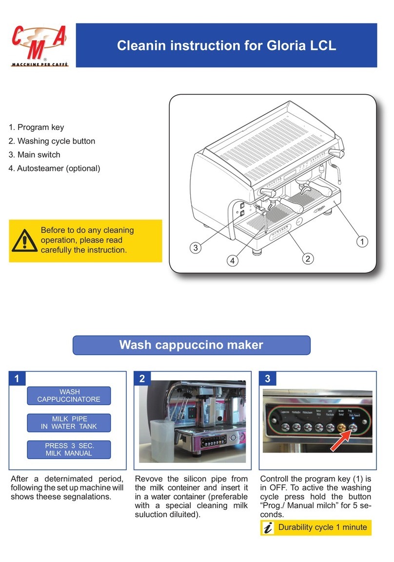
CMA Dishmachines Gloria LCL Configuration guide

CMA Dishmachines
CMA Dishmachines GLORIA User manual

CMA Dishmachines
CMA Dishmachines Luna User manual

CMA Dishmachines
CMA Dishmachines MARISA User manual

CMA Dishmachines
CMA Dishmachines AK User guide

CMA Dishmachines
CMA Dishmachines ADRIA series User manual

CMA Dishmachines
CMA Dishmachines Sara AK User manual

CMA Dishmachines
CMA Dishmachines AKC User manual