MODEL CMA-180VL Service & Parts Manual Rev. 2.01 Page 7
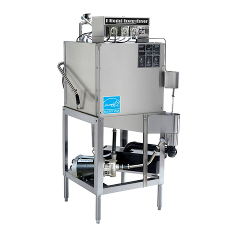
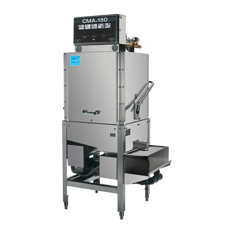
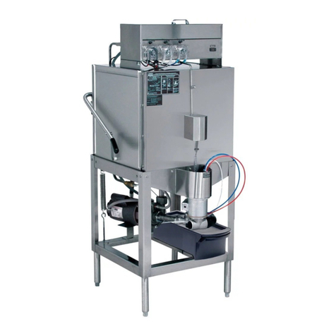
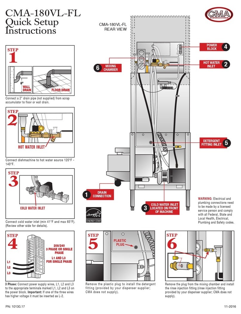
The CMA-180VL is a hot water sanitizing, single rack, door-type dishmachine. It is a stand-alone
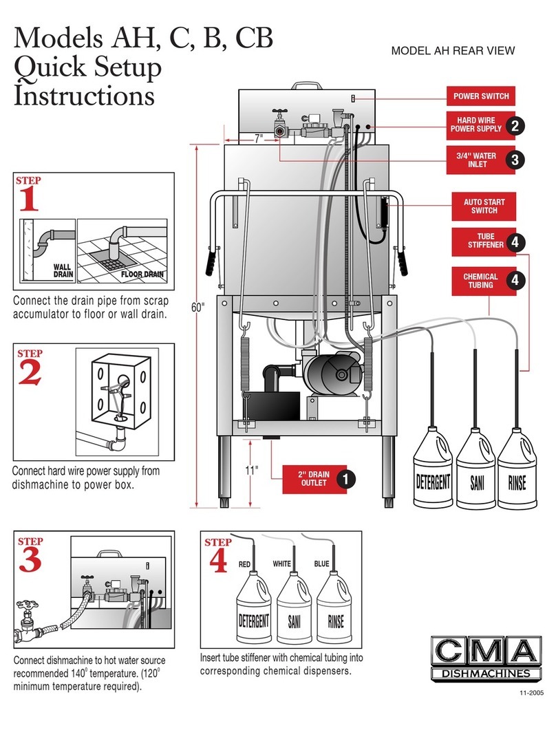
machine featuring a self-contained booster heater. The only external connections necessary are
power supply, water supplies, drainpipe, and chemical dispensers. The machine utilizes re-
circulated wash water and fresh water final rinse.
The machine is equipped with the built in Heat Recovery System which reduces significantly the
humidity in the dishwashing room. The Heat Recovery System uses the heat of the steam
generated during the wash cycles to warm up the in-feed water (41F -65F) before entering the
booster heater.
Operation of the CMA-180VL is automatic. When the door is opened and then closed, the wash
cycle begins automatically. To initially fill the machine daily, press auto fill rocker switch. The
machine is full when water begins to flow into the scrap trap. The wash tank heater will maintain
the wash water temperature at 155°F. The booster heater will produce a minimum of 180°F final
rinse water each cycle providing the incoming cold water supply is a minimum 41°F.
This manual is structured to provide a complete reference guide to the CMA-180VL. It is
presented in a manner that all users will be able to comprehend and use as an effective tool in
supporting the operation and maintenance of the dishmachine. The first section explains how the
machine is packaged and what to look for when receiving the machine.
Instructions are provided in the manual explaining how to unpack the machine and then install
and set up the machine for use. Requirements are given for plumbing, wiring, and space
considerations. These attributes of the machine are always taken into consideration by our well-
trained sales representatives prior to the order being placed. In the manual, additional installation
guidance is given to ensure the machine can run at optimum conditions.
The Operation Section of the manual may be used for instruction and procedures when required.
We make this portion of the manual easy to understand so that all levels of operators may be
able to read and comprehend the operation of the machine. The function of the machine itself is
mostly automatic and takes little training to put into full operation. The Operation Section also
includes diagnostic considerations for the machine when problems occur.
Our mission is to provide our customers with the highest quality products and the highest
quality service, always delivering more than we promise and more than he or she expects.
We will strive to do business the way the customer wants to do business, on a mutually
profitable basis.
We are committed to providing the best machines and customer service in the food
industry and your feedback is welcome.
CMA warranties the workmanship of the machine.
Warning:
Failure to provide soft water (3g or less), will void the machines warranty.
the CMA-180 VL has a Heat Recovery (HR) system comprised of heat exchange coils
that can become restricted or clogged if the water supplied to the machine contains lime scale,
known as hard water conditions. The cold water supplied to the CMA-180 VL should be analyzed
and treated to maintain maximum 3 grains water hardness to prevent scaled conditions. First sign
of a problem will be restricted or zero rinse flow to the rinse arms.
DISCLAIMER OF LIABILITY OF WARRANTY
: CMA EXPRESSLY DISCLAIMS ANY AND ALL WARRANTIES, EXPRESS OR IMPLIED, RELATING TO THE INSTALLATION OF ANY AND ALL
CMA EQUIPMENT THAT IS INSTALLED BY CHEMICAL DEALERS, CONTRACTED SERVICERS OR THIRD PARTY SERVICERS TO CMA EQUIPMENT. IF THE INSTALLATION
INSTRUCTIONS ARE NOT FOLLOWED EXACTLY (TO THE LETTER), OR, IF ANY PERSON OR COMPANY CONDUCTING THE INSTALLATION OF THE CMA EQUIPMENT, REVISE THE
INSTALLATION PROCEDURES OR ALTER THE INSTRUCTIONS IN ANY MANNER, THE CMA WARRANTY BECOMES VOID. IF, DUE TO THE IMPROPER INSTALLATION OF CMA
EQUIPMENT, THIS EQUIPMENT CEASES TO OPERATE PROPERLY OR AFFECTS OTHER PARTS OF THE CMA DISHWASHING EQUIPMENT, IN THAT THE OTHER PARTS BECOME
DEFECTIVE, THE CMA WARRANTY BECOMES VOID. CMA WILL NOT BE LIABLE OR RESPONSIBLE OR WARRANT CMA EQUIPMENT, DUE TO IMPROPER INSTALLATION OF ANY
CMA MODEL DISHWASHER.
