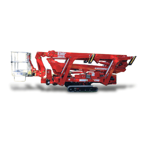
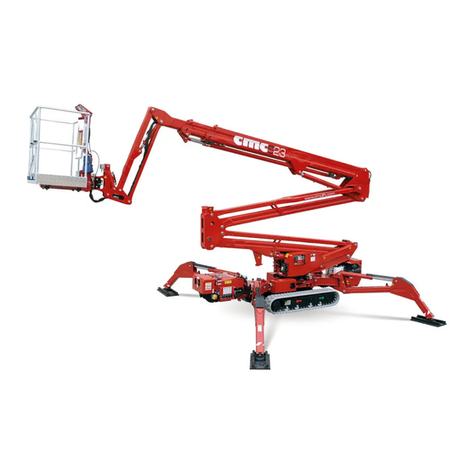
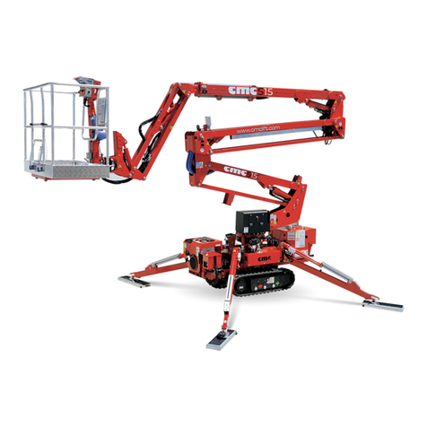
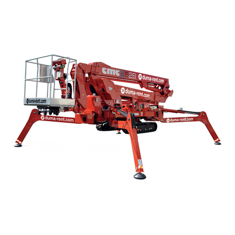
CMC S19HD PRO User manual

MAN.234 Rev.3 ENG - Use and maintenance manual S19HD PRO page
1
of
83
0 Introduction
hank you for the trust you have showed us buying a C.M.C. mobile
elevating work platform (MEWP). We are sure you will be pleased
with your choice.
0.1
Content of the manual
This manual contains the technical specifications and the instructions for
transfer, use and maintenance of the MEWP. While drawing up this manu-
al, we took into consideration all the operations that are part of a normal
use and a regular maintenance of the machine. So, for a correct and opti-
mum use, you must follow the described instructions carefully.
This manual has been drawn up in order to:
Show the technical features of the machine;
Describe the control stations and their commands;
Provide with the instructions for the transport, placement and use
of the machine;
Describe the safety devices;
Point out the potential risks and/or possible dangerous situations;
Provide with the necessary instructions for the ordinary mainte-
nance operations;
Provide with the instructions for the filling of the check register.
THE USE AND MAINTENANCE MANUAL IS CONSIDERABLE
AS A PART OF THE MACHINE. In case of sale of the MEWP,
please give this manual to the new owner.
LEGEND OF THE SYMBOLS USED IN THIS MANUAL:
(CAUTION) = warns the user about the risk of serious damages
to people or to part of the equipment or the machine,
if you do not obey the safety regulations.
(WARNING)
= notifies the possibility of minor injuries to people
or little damages to the platform or machine parts.
(FORBIDDEN) = prohibition signal
(
OBLIGATION) = obligation signal
(CAUTION)
=warns the user about the risk of environmental
pollution.
*
(OPTIONAL)
=indicates an optional outfit.
(IMPORTANT NOTE) = indicates information and suggestions useful to
work with the MEWP.
This manual is addressed to:
users: operators, ground assistants, guard staff, safety man-
ager, service manager;
manufacturers, dealers, owners, lessors or lessee, brokers.
T
www.duma-rent.com

MAN.234 Rev.3 ENG - Use and maintenance manual S19HD PRO page
2
of
83
0.2
Disclaimer
C.M.C. declines all responsibility in case of partial or total non-observance
of the following instructions
Before proceeding with any operation of use of the machine, the
user is obliged to read carefully the text of this manual, with refer-
ence to sections relative to specific work activity to perform.
The use of the machine must be entrusted only to trained and au-
thorized staff. This manual cannot replace in any way a suitable
experience that the staff in charge must have gained previously on
similar machines or that they will able to get on this machine, un-
der the guidance of an already trained staff.
The user must work within the functional limits of the machine and
perform a constant and diligent maintenance, using only original
spare parts indicated by C.M.C.
The operator shall carefully know the safety standards foreseen by
national and international legislations and apply them during all
operations with the MEWP.
The guarantee of proper functioning and full compliance of
the machine with the intended service is strictly dependent
on the correct application of all the instructions contained in
this manual.
The non-compliance with the previous items automatically
invalidates the warranty.
0.3
Where and how to keep the manual
The manual must be stored and kept in the best possible
condition (away from sunlight), in a suitable place, for the
purpose of always being available for consultation.
This manual (or its copy) must always be on the machine (in
a case near the turret) for an immediate consultation by the op-
erator during working operations.
Another copy shall be hold by the basket operator during the
working period inside the internal documents case.
In case of loss or deterioration, the replacement documenta-
tion must be requested to C.M.C. s.r.l, citing the code of this
manual.
0.4
Regulatory references
This manual has been drawn up according to the following na-
tional and international laws and directives:
Directive 2006/42/CE ISO 3864 EN 280:2015
Directive 93/68/CEE ISO 4302 EN 349
ISO 12100 ISO 4305 EN 60068-2-64
ISO 13849-1-2 ISO 4309 EN 60204-1-32
ISO 13850-13854 ISO 20381 EN 60529
ISO 13857 EN 13001 EN 62061
ANSI/SAIA A92.20-2018 ANSI/SAIA A92.24-2018 ANSI 92.6-2006
ANSI/SAIA A92.22-2018 ANSI Z359.1 CSA 354.1-2006
www.duma-rent.com

MAN.234 Rev.3 ENG - Use and maintenance manual S19HD PRO page
3
of
83
0.5
Amendments and integrations
The information and legislative references present in this manual are those
in force when the machine has been placed on the market.
Due to the constant and continuous improvement of their product by the
manufacturers, the supplied machine could present some technical speci-
fications different from those described on this manual. Any change will be
however accompanied with specific documents attached explaining func-
tional characteristics. In case of differences in comparison with the basic
contents of this manual, the user is kindly asked to contact C.M.C. to re-
ceive supplementary technical specifications.
As this manual includes both current and optional components, you could
find information not applicable to your machine.
C.M.C. reserves the right to update its production and its instruction man-
uals (without prior notice) according to the development of the technique,
to the acquisition of new experiences and/or the change of law provisions,
without being anyway obliged to intervene on the previously sold machines
and on their manuals.
No part of this publication can be translated, modified or reproduced (even
partially) without the expressed authorization of C.M.C. s.r.l.
C.M.C. reserves the right to modify - totally or partially - any data or speci-
fication of this publication (without prior notice).
Data and references indicated in this manual are those in force at the time
of printing.
Year 2019
C.M.C. s.r.l.
www.duma-rent.com

MAN.234 Rev.3 ENG - Use and maintenance manual S19HD PRO page
4
of
83
1 Specifications
1.1
Technical sheet
PERFORMANCE
Max. working height 18,70 m 61.35 ft
Max. work outreach
(long area with 200/220 kg 8,60 m 28.22 ft
Max. work outreach
(long area with 80 kg 11,50 m 37.73 ft
Max. load on the basket 220 kg (USA
200 kg (CE
485 lb (USA
441 lb (CE
Turret rotation +/-355° (710° continuous
Basket rotation (*optional +90°/-87°
(P) Max. slope to stabilize 26°/49%
(W) Max. ramp slope (attack 31°/60%
(X) Max. slope to travel 17°/31%
Travel speed 0,60 - 1,38 km/h 0.37 - 0,86 mph
DIMENSIONS
(A) Basket height 1,10 m 3.61 ft
(B) Basket width 0,60/0,70 m 1.97/2.30 ft
(C) Basket length 0,80/1,20/1,40 m 2.62/3.94/4.59 ft
(D) Total length 4,85 m 15.91 ft
(F) Height in driving position 1,99 m 6.53 ft
(G) Total width (without basket 0,90 m 2.95 ft
(H) Clearance from the ground
in transport configuration 0,18 m 0.59 ft
(H’) Max. height to stabilize 1,00 m 3.28 ft
(H’’) Max. height to climb over
an obstacle
0,50 m
1.64 ft
Tracks (l x h 1,75 x 0,25 m 5.74 x 0.82 ft
Width tracks adjustment
(*optional 0,90/1,30 m 2.95/4.27 ft
(J) Max. longitudinal stabilization 4,14 m 13.58 ft
(K) Max. cross stabilization 3,54 m 11.61 ft
(N) Min. longitudinal stabilization 3,54 m 11.61 ft
(O) Min. cross stabilization 2,72 m 8.92 ft
Intermediate cross stabilization 3,12 m 10.24 ft
Outriggers plate Ø 0,18 m 0.59 ft
WEIGHT AND PRESSURES
Total weight 2617 kg 5769 lb
(R) Max. pressure on the foot 6,6 Kg/cm²
(64,72 N/cm² 93.87 lb/in
2
(S) Max. pressure on the track 0,17 Kg/cm²
(1,67 N/cm² 2.42 lb/in
2
(T) Max. pressure in travel 400 Kg/m²
(3,92 KN/m² 81.93 lb/ft
2
(U) Max. pressure in work
(4 feet opened
228 Kg/m²
(2,24 KN/m² 46.70 lb/ft
2
(V) Max. pressure in work
(4 feet closed
242 Kg/m²
(2,38 KN/m² 49.57 lb/ft
2
POWERS
Standard hydraulic feed 1 Honda GX390 petrol, 8.7 kW (11.7 HP ,
3600 rpm
*Optional feeds
2 Yanmar L100V diesel, 6.8 kW (9.1 HP ,
3600 rpm
3 Honda iGX390 petrol, 8.7 kW (11.7
HP , 3600 rpm
4 Kubota Z602-E4B diesel, 10.8 kW (14.5
HP , 3200 rpm
5 Electric engine 110/120/230 V
6 Motor G0901306, 9 kW, 48 V, with
lithium batteries 160 Ah
7 Hybrid version
Fuel tank capacity 6,1/15 l
www.duma-rent.com

MAN.234 Rev.3 ENG - Use and maintenance manual S19HD PRO page
5
of
83
Max allow d sp ds according to USA/EU standards
Max allowed lifting and descending speed of
the MEWP 0,4 m/s (1.31 ft/s
Max allowed boom extension and withdrawal
speed 0,4 m/s (1.31 ft/s
Max allowed rotation speed 0,7 m/s (2.3 ft/s
Max allowed manual force in the basket with 1
operator 400 N
Tightening torque
Bolts of th b aring M16 cl 10.9 28 daNm
www.duma-rent.com

MAN.234 Rev.3 ENG - Use and maintenance manual S19HD PRO page
6
of
83
1.2
Identification plate
On the MEWP turret, there is a plate with all the identification data of the
machine:
TYPE S19
MANUFACTURER
C.M.C.
MODEL S19HD (PRO) YEAR 2020
SERIAL NR. S19A2140 TOT. WEIGHT 6173 lbs
CAPACITY
441 lbs
INCLUDING
2 persons
MAX HYDRAULIC OPERATING PRESSURE
3336 PSI
MAX MANUAL HORIZONTAL FORCE ALLOWED
90 lbs
MAX WIND SPEED ALLOWED
28 mph
MAX FRAME INCLINATION ALLOWED
1°
EXTERNAL POWER SOURCE
230 V 50 Hz
C.M.C. s.r.l.
Via Bitritto, 119
70124 BARI - ITALY
Tel. 080 5326606/557
http://www.cmclift.com
E-mail: info@cmclift.com
Picture 1: identification plate.
www.duma-rent.com

MAN.234 Rev.3 ENG - Use and maintenance manual S19HD PRO page
7
of
83
1.3
CE certification
C.M.C. s.r.l. states under its own responsibility that S19HD PRO was de-
signed and produced in compliance with national and European standards,
and that the machine is identical to the model submitted to control and test
for the “CE certification” by the Notified Institute nr. 1878 - VERICERT
s.r.l. - via L. Masotti, 5 – 48124 Ravenna – Italy.
1.4
TÜV certification
C.M.C. s.r.l. states under its own responsibility that S19HD PRO was de-
signed and produced in compliance with US standards ANSI/SAIA
A92.20:2018 and that the machine is identical to the model submitted to
control and test for the “TÜV certification” by TÜV SÜD America Inc.
TÜV SUD America Inc. is an OSHA recognized NRTL and a Standards
Council of Canada accredited certification body.
1.5
Classification
The mobile elevating work platform (MEWP) S19HD PRO belongs to
group B: the vertical projection of the center of the area of the MEWP in
different platform configurations specified by the manufacturer can be out-
side the tipping lines (EN 280 par. 1.4 - ANSI/SAIA A92.20 par. 3).
As for the displacement, it belongs to type 1: travelling is only allowed
with the MEWP in its transport configuration or in the stowed position (EN
280 par. 1.4 - ANSI/SAIA A92.20 par. 3).
1.6
Loading cycles
The machine is expected to live for 40.000 working cycles
1
(i.e. 10 years,
40 weeks per year, 20 hours per week, 5 cycles per hour).
Within this term, the machine must undergo at least 2 (two) in-depth
checks (structural, mechanical, electric, elements, etc.), in case of heavy
uses (frequent use at the performance limit, unfavourable environmental
conditions such as steel systems, paper mills and so on) it is better to in-
crease the checks. Anyway, it is advisable to have the state of the
machine checked by the manufacturer factory or by an authorized
assistance point, at least every 1500 – 2000 working hours or once a
year.
1
Loading cycle: cycle starts from the access position, continues performing the
work and finishes returning to the access position.
www.duma-rent.com

MAN.234 Rev.3 ENG - Use and maintenance manual S19HD PRO page
8
of
83
1.7
Working diagram and stabilization are-
as
Picture 2a: working diagram.
Picture 2b: stabilization areas.
www.duma-rent.com

MAN.234 Rev.3 ENG - Use and maintenance manual S19HD PRO page
9
of
83
2 Description and pur-
pose
2.1
Definition
The machine is called S19HD PRO and it is a mobile elevating work
platform (MEWP):
•machine/device intended for moving persons, tools and material to
working positions, consisting of at least a work platform with con-
trols, an extending structure and a chassis (ANSI/SAIA 92.20 par.
3);
•mobile machine intended to move persons to working positions,
where they are carrying out work from the work platform, with the
intention that persons are getting on and off the MEWP only at ac-
cess positions at ground level or on the chassis and which consists
as a minimum of a work platform with controls, an extending struc-
ture and a chassis (EN 280 par. 3.1).
It is forbidden to access to or exit from the work platform at dif-
ferent levels.
2.2
Machine purpose
The MEWP S19HD PRO is a machine which enables the operators to
reach the working place when this is high-positioned.
The machine has been designed for an essentially vertical use. It
must be transported only when it is totally folded in the transport po-
sition.
The use of the machine is allowed only to professional staff,
properly trained and specialized.
2.3
Description of the main components
Picture 3: main components of the MEWP.
www.duma-rent.com

MAN.234 Rev.3 ENG - Use and maintenance manual S19HD PRO page
10
of
83
2.3.1
Frame
The frame 1(Picture 3) is a steel structure having a quality appropriate in
order to distribute the weight of the equipment when the MEWP is in driv-
ing position. The frame is equipped with 4 hydraulic jacks used for stabili-
sation [2 front stabilizers cylinders 2(Picture 3), 2 rear stabilizers cylinders
3(Picture 3). The base 4(Picture 3) for the support slewing ring is on the
frame and through the rotation unit allows the tilting of the equipment.
2.3.2
Turret
The turret 5(Picture 3), made of quality steel, is fixed to the bearing (slew-
ing ring). The rotation of the superstructure is allowed by a hydraulic motor
with brake normally closed, constrained to the turret.
2.3.3
Pantograph
The pantograph 6 (Picture 3) is constituted by two parallel arms (panto-
graph upper crank 6' (Picture 3) and pantograph lower crank 6'' (Picture 3)
and by the pantograph connecting rod 7 (Picture 3). The arms (tubular with
rectangular section, bended and electro-welded) and the connecting rod
are made with high quality steel sheets. The movement of the pantograph
(lifting and lowering the pantograph) is obtained thanks to the hydraulic cyl-
inder for lifting the pantograph 12 (Picture 3). This cylinder is fastened to
the turret (barrel side) and to the upper pantograph crank (rod side) and is
equipped with double-acing balancing valve.
The pantograph has a working range from 0° to about +65° with respect to
the horizontal.
2.3.4
Telescopic boom
The telescopic boom 8(Picture 3) is hinged to the turret. The telescopic
boom is composed of three elements: a fixed boom 9(Picture 3) hinged to
the turret and two telescopic booms
10
11 (Picture 3).
The extraction movement (or return) of the telescopic boom is obtained by
moving the "telescopic boom extraction cylinder" 13 (Picture 3).
The lifting (or lowering) movement of the telescopic boom is obtained by
moving the "telescopic boom lifting cylinder" 14 (Picture 3).
2.3.5
Basket
The basket 16 (Picture 3) is connected to the second boom of the tele-
scopic element through the oscillating support 15 (Picture 3). It is made
with tubular aluminium or steel, bent, welded and hot galvanised, covered
in fibreglass
*
or made in a structure completely in fibreglass
*
; it is
equipped with side or front opening for operator access. The opening is
self-hinged and built to avoid accidental openings. The platform is provided
with attachments for the safety belts, a guard-rail at a height of 1.1 m from
the floor, an intermediate guard-rail and a foot guard band along all the
sides of the platform. The floor is in anti-skid and self-draining aluminium.
www.duma-rent.com

MAN.234 Rev.3 ENG - Use and maintenance manual S19HD PRO page
11
of
83
3 Control positions
3.1
Engines ignition station
The machine engine ignition station is generally positioned on the chassis
(Picture 4a).
Picture 4a: engine ignition station.
It consists of an electrical panel in which there are:
•the SK key: through it, it is possible to turn on the electric system
and start the endothermic engine;
•the hour counter;
•the green light 5indicating system power supply: it is on when
the SK key is in position 1;
•the red light 4 which signals low pressure to the engine oil;
•the red light 3 which monitors coolant level;
•the orange light 2 indicating the spark plugs working;
•the red light 1 which signals an alternator failure;
•the control station selector 6: at left it enables the basket control
station, at right the radio control on the ground
•the platform consent light 7:if lighted on, it allows the maneu-
vers of the aerial part only with stabilization correctly performed.
•the stabilization consent light 8:if lighted on, it allows the
movement of the outriggers only with the boom and the panto-
graph rested on their supports.
•the fuse box;
•the emergency red mushroom-shaped button EB that blocks
the machine, removing the power supply to the control circuits.
This button has priority over all other commands; thus, it allows on-
ly manual descent to the ground.
The emergency button has a mechanical locking device; there-
fore, it must be unlocked by turning it clockwise to reactivate
the normal machine working.
•the “dead man” stabilizers button 9: it must be held pressed to-
gether with other levers of outriggers control station to stabilize or
destabilize.
If the machine is equipped with a petrol engine or in a hybrid version (pet-
rol + electric engine), the control station includes an ignition key lock posi-
tioned directly on the motor group (Picture 4a): turning to the right the SK
key, it is possible to switch on the electric system and start the endother-
mic engine.
SK
6
5
7 8
1
2
3
4
EB
9
SK
www.duma-rent.com

MAN.234 Rev.3 ENG - Use and maintenance manual S19HD PRO page
12
of
83
Picture 4b: ignition station in case of hybrid or full lithium version.
In hybrid version and in a full lithium equipment, the electrical box mounted
on the chassis (Picture 4b) changes as below:
•the green light 5indicating machine power supply: it is on
when the SK key is in position I;
•the control station selector 6: at left it enables the basket control
station, at right the radio control on the ground.
•the platform consent light 7:if lighted on, it allows the maneu-
vers of the aerial part only with stabilization correctly performed.
•the stabilization consent light 8:if lighted on, it allows the
movement of the outriggers only with the boom and the panto-
graph rested on their supports.
•the emergency red mushroom-shaped button EB that blocks
the machine, removing the power supply to the control circuits.
This button has priority over all other commands; thus, it allows on-
ly manual descent to the ground.
The emergency button has a mechanical locking device; there-
fore, it must be unlocked by turning it clockwise to reactivate
the normal machine working.
•the “dead man” stabilizers button 9: it must be held pressed to-
gether with other levers of outriggers control station to stabilize or
destabilize.
•the fuse box;
•the battery charge indicator 10;
•the hour counter 11.
Before performing any operation, it is necessary to place the
ignition key in position 1.
Picture 5: left side of chassis box.
In all engine equipment, on the left side of this case (Picture 5), you can
find:
6
5
EB
9
7
8
10 11
2 3 4
www.duma-rent.com

MAN.234 Rev.3 ENG - Use and maintenance manual S19HD PRO page
13
of
83
•the red sealed key 2to bypass engine anomalies that block the
platform manoeuvres;
•the yellow sealed key 3to bypass the emergency stop in the
basket, only in case of danger;
•the red sealed key 4to enable the emergency electropump;
•the remote connection on/off lever and the connector to re-
ceive technical assistance from C.M.C. Service or authorized
workshops;
•the 12 V socket;
•the buzzer.
3.1.1
Ignition of the endothermic engine
In order to start the endothermic engine, turn the SK key all the way to the
right up to the symbol .
Before starting the engine, especially if the MEWP is used in workplaces
with low atmospheric temperatures, it is advisable to heat the spark plugs
of the machine engine while keeping the key on the symbol for a few
seconds: this will cause the corresponding orange light 2(Picture 4a) to
turn on.
The ignition of the endothermic engine can also be carried out with the ra-
dio/wired control. Using it on the ground or in the basket:
• turn the SK key to position 1;
• move the lever in the Picture 5 upwards, present on the left side of
the radio/wired control under the joystick J1 (Picture 8);
• in this case, the green light 5(Picture 4a) will light up on the switch-
ing on/off station to signal the correct power supply of the machine.
To switch off the endothermic engine, you can alternatively:
•turn the SK key all the way to the left on position 0;
•lift the lever 8in the Picture 8;
•press, in emergency situations, one of the emergency buttons on
the machine (par. 4.5.1).
3.1.2
Switching on/off the electric engine (*optional)
On the machine, it can also be provided an auxiliary electric engine
(*optional).
If you choose to use it:
•connect the 110/120/230 V socket to the nearest electrical source;
Picture 6: power line socket.
•from the radio/wired control, start the engine by pushing the lever
in Picture 5 downwards;
•the power supply is signaled by the lighting up of the green led 5
(Picture 4a) on the switching on/off station.
To switch off the electric* engine, it will be enough to alternatively:
•turn the SK key all the way to the left on position 0;
•lower the lever mentioned above;
•press, in emergency situations, one of the emergency buttons pro-
vided on the machine (par. 4.5.1).
It is not possible to turn on both the endothermic engine and
the electric engine at the same time.
3.1.3
Other power supplies *optional
The machine can be supplied on request completely with a 48 V electric
engine powered by 160 Ah lithium batteries or with a hybrid feed.
Power line
socket
Machine plug
www.duma-rent.com

MAN.234 Rev.3 ENG - Use and maintenance manual S19HD PRO page
14
of
83
It is not possible to have the 48 V electric engine and the
110/120/230 V engine fitted on the machine at the same time.
The start and stop of the 48 V electric engine will be the same shown
above for 110/120/230 V electric engine.
To recharge the batteries:
1. couple the 110/120/230 V socket (power line) to the plug on the
machine and move upward the button provided on the machine's
thermal magnetic panel;
2. from this moment the batteries will be charging and, if the electric
system is ON, the progress of the charging process will be shown
on the control station LED panel (Picture 9).
When the state of batteries charge, during the use, reaches the
lowest level (under 10%), all work maneuvers will be interrupt-
ed, and it will only be possible to close the machine again.
It is absolutely forbidden to direct high-pressure jets of water
onto the support containing the battery pack. High water pres-
sure could generate serious and irreversible problems in the
operation of the machine.
3.2
Platform control stations
There are the following platform control stations:
1. the first one (operating) is the AUTEC radio control station (Picture
8);
2. the second one (operating) is the AUTEC wired remote control sta-
tion in the basket;
3. the third one (emergency) is totally hydraulic, with electrovalves
distributor and stabilizers levers, and it is located on the frame.
It is not possible to use two different control station at the
same time.
The system will select as actual control station the first one that will be
used by the operator. Once the AUTEC radio control station is connected,
it will become the actual control station, and in order to select a different
control station you need to turn off and back on the system by the ignition
key or any of the emergency buttons on the machine (except the one on
AUTEC radio control).
3.2.1
Platform (operating) control station
The main platform (operating) control station consists of the AUTEC radio
control.
It can be activated only by carrying out the connection procedure de-
scribed below (radio control activation directly excludes the basket control
station).
Radio control link procedure:
1. To connect the radio control, press the green Start/Link button SL
(Picture 7) down on the left side.
www.duma-rent.com

MAN.234 Rev.3 ENG - Use and maintenance manual S19HD PRO page
15
of
83
Picture 7: start/link button on radio control.
2. if the radio control is not correctly connected to the machine, the
green led on the upper right side of the LED panel flashes intermit-
tently and a buzzer on the electric box emits an intermittent acous-
tic signal.
3. press the start/link button again: when the connection is complete,
the buzzer stops and the green led starts to light up at the rate of
two flashes interspersed with a pause.
SL
CK
www.duma-rent.com

MAN.234 Rev.3 ENG - Use and maintenance manual S19HD PRO page
16
of
83
Picture 8: radio control station.
J1 J2
7 8 9 10 11 12
EB
J5
J6
J4
J3
www.duma-rent.com

MAN.234 Rev.3 ENG - Use and maintenance manual S19HD PRO page
17
of
83
It has the following commands:
-on the left side:
• a green start/link key;
• a blue coding key CK (Picture 14), which puts the console in
communication with the machine control unit. Be careful not to
lose it!
• parking button P: it has multiple functions; one of the most im-
portant is the automatic return of the booms in the rest position.
-on the central electronic panel:
• joystick J1 for travel of left track (orange) / basket levelling
(white) / basket rotation (yellow);
• joystick J2 for simultaneous widening/narrowing of all
tracks (orange) / telescopic boom extraction/return (yellow);
• joystick J3 for boom lifting/lowering (yellow);
• joystick J4 for lifting/lowering and extraction/return of pan-
tograph (yellow);
• joystick J5 for simultaneous widening/narrowing of all
tracks (orange) / turret rotation (yellow);
• joystick J6 for travel of right track (orange) / jib lift-
ing/lowering;
• emergency red mushroom-shaped button EB that blocks the
machine, removing the power supply to the control circuits. This
button has priority over all other commands; thus, it allows only
manual descent to the ground. The emergency button has a me-
chanical locking device; therefore, it must be unlocked by turning
it clockwise to reactivate the normal machine working.
• lever 7for travel block bypass;
• lever 8for endothermic or electric engine power on/off;
• lever 9for lowering/raising stabilizers during load-
ing/unloading operations;
• travel speed selector 10: “turtle” mode = slow speed, “hare
mode” = medium speed, “double hare” mode = high speed;
• lever 11 for automatic stabilization/destabilization;
• lever 12 for "Home function” / basket levelling (dead man
device).
Carry out the basket levelling operation only when the aerial
part of the MEWP is in transport configuration.
It is strictly forbidden to carry out the basket levelling operation
when the machine is developed.
-on the right side:
• electropump activation button.
www.duma-rent.com

MAN.234 Rev.3 ENG - Use and maintenance manual S19HD PRO page
18
of
83
Picture 9: LED panel with indicator lights.
1
3
5
6
7
8
10
12
15
16
17
19
20
23
24
25
26
27
29
30
31
32
Table 1: assignment number for LEDs matrix.
1. LED – LEFT FRONT STABILIZER TO THE GROUND
2.
3. LED – RIGHT FRONT STABILIZER TO THE GROUND
4.
5. LED – DANGER/GENERIC FAULT
6. WARNING LIGHT - ANTICRASH
7. EARLY WARNING LIGHT - MOMENT LIMITER
8. LED – 85-100% BATTERY CHARGE (*optional)
9.
10. LED – FRAME LEVELLED
11.
12. LED – BASKET CENTRED
13.
14.
15. WARNING LIGHT – MOMENT LIMITER BLOCK
16. LED – 60-85% BATTERY CHARGE (*optional)
17. LEFT REAR STABILIZER TO THE GROUND
18.
19. RIGHT REAR STABILIZER TO THE GROUND
20. LED – BASKET LEVELLED
21.
22.
23. LED – BASKET OVERLOAD
24. LED – 35-60% BATTERY CHARGE (*optional)
25. LED – BOOMS CLOSED
26. LED – TURRET CENTRED
27. LED – BOOMS WITHDRAWN
28.
29. LED – AERIAL PART USE CONSENT
30. LED – MACHINE STABILIZED
31. LED – MACHINE READY TO TRAVEL
32. LED – 10-35% BATTERY CHARGE (*optional).
If all leds of battery* charge flash, a battery malfunction or a
connection missed (CAN-bus) is signalled.
If only the bottom led (10%) flashes, the battery* charge is too
low (under minimum threshold) and the machine is near to go
in block.
3.2.1.1
Recharge of radio control battery
The radio control is equipped with two interchangeable batteries (one mounted
and one spare).
It is advisable to always keep the unused battery charged and, in any case, to
ensure that it is being charged during non-working hours.
To charge the battery, simply allocate it in the charging compartment of the radio
control storage location (Picture 10).
www.duma-rent.com

MAN.234 Rev.3 ENG - Use and maintenance manual S19HD PRO page
19
of
83
Picture 10: charging compartment of the radio control battery.
If, during works, the battery of the AUTEC radio control is low, it could be-
come a wired remote control by cabling its plug to the frame connector or
to the basket connector (Picture 11).
Picture 11: frame and basket connectors for wired remote control.
3.2.2
Basket (operating) control station
The functions contained on the basket control station are the
same as those of the platform (operating) control station in Pic-
ture 8 and are indicated by the same symbols described above.
In the basket (operating) control station, clearly, the parking button Pand
the lever 7are missing.
Picture 12: basket control station + “dead man” pedal.
The “dead man” pedal (*optional) must be pressed simultaneous-
ly with joysticks for all manoeuvres by the basket control station.
www.duma-rent.com

MAN.234 Rev.3 ENG - Use and maintenance manual S19HD PRO page
20
of
83
3.3
Emergency control stations
The emergency control station includes:
•outriggers control station;
•errors display;
•emergency workbench for recovery procedure.
3.3.1
Outriggers control station
The "outriggers control station” is fixed aboard the machine frame.
The manual stabilization/destabilization manoeuvres are carried out by the
operator on the ground through the stabilizers control levers (Picture
13):
Picture 13: outriggers control station.
•
lever 1for left rear stabilizer;
•
lever 2for right rear stabilizer;
•
lever 3for left front stabilizer;
•
lever 4for right front stabilizer;
•
lever 5for tracks: it, upward, restricts the tracks and downward en-
large them.
Each lever, moved upward, runs the lifting of the stabilizer and if moved
downward the lowering of it.
The “dead man” stabilizers button 9 (Picture 4) must be held pressed
together with the levers of outriggers control station to stabilize or
destabilize.
3.3.2
Display
The display (Picture 14), placed at left side of the machine frame, near the
outriggers control station, shows the machine status when there is any
anomaly or system error.
Picture 14: display.
1
2
3
4
5
www.duma-rent.com
Table of contents
Other CMC Lifting System manuals
Popular Lifting System manuals by other brands

Future Automation
Future Automation UBLS Application notes

Autoadapt
Autoadapt CAROLIFT 140 installation instructions

Nussbaum
Nussbaum 4.45 H operating instructions

Peak
Peak KAL-12A Installation and service manual

LSP inc.
LSP inc. LSC850D owner's manual

Lift Tech Marine
Lift Tech Marine DC REMOTE GEN 2 owner's manual

JLG
JLG Skytrak 6036 Operation & safety manual

probst
probst SPEEDY VS-140/200 operating instructions

Ravaglioli
Ravaglioli KPN250LIKA Translation of the original instructions

Plymovent
Plymovent BALANCER-200 Series Installation and user manual

Vestil
Vestil CART-550-AS instruction manual

Aqua Creek
Aqua Creek F-105LAR instructions