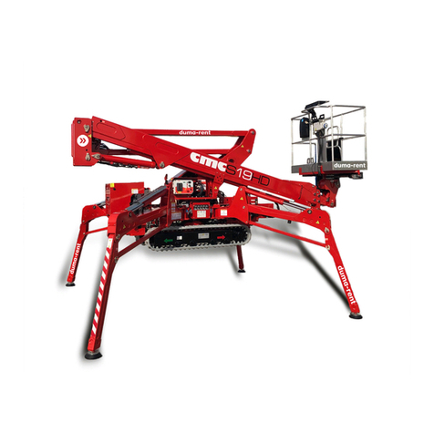
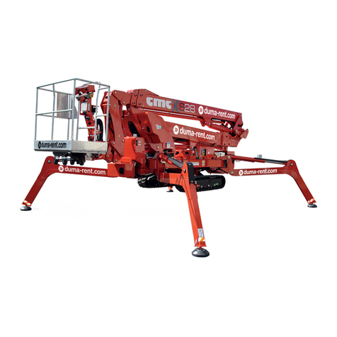
CMC S19 User manual

MAN. 181 rev. 3 Use and maintenance manual Sup24
1 di 77
0 Introduction
hank you for choosing to purchase a CMC MEWP (aerial work
platform), we are sure you will be pleased with your choice.
0.1
Use and maintenance manual
This manual is added to the sold machine and contains the instructions for
its transfer, use and maintenance. While drawing up this manual, we took
into consideration all the operations that are part of a normal use and
regular maintenance of the machine. So for a correct and optimum use,
you have to follow the described instructions carefully
This manual has been drawn up in order to
:
Describe the use of the machine
Show the main technical specifications of the machine
Provide with the instructions for the placement and use of
the machine
Describe the safety devices
Point out the potential risks and/or possible dangerous
situations
Provide with the necessary instructions for the ordinary
maintenance operations
Provide with the instructions for the filling of the check
register.
THE USE AND MAINTENANCE MANUAL IS INTEGRAL
PART OF THE MACHINE. In case of sale of the MEWP,
please give this manual to the new owner.
KEY FOR THE SYMBOLS USED IN THIS MANUAL
(CAUTION) = warns the user about the risk of serious damages
to people or to part of the equipment or the vehicle,
ifyoudo notobeythesafetyregulations.
(WARNING) = notifies the possibility of minor injuries to people
orlittledamages totheplatformorvehicle parts.
(FORBIDDEN) = prohibitionsignal.
(
OBLIGATION) = obligationsignal.
(CAUTION)
=warns the user about the risk of environmental
pollution.
*
(OPTIONAL)
=indicatesanoptionaloutfit..
(IMPORTANT NOTE)
This instruction manual is addressed to:
Operators
Ground assistants
Staff in charge of the platform (MEWP) guard
Security manager
Maintenance manager
T

MAN. 181 rev. 3 Use and maintenance manual Sup24
2 di 77
KEY FOR THE SYMBOLS USED IN THE IN THE STICKERS
1 CW rotation / external leveling
2
R
eturn and
l
owering Boom
1 /
backwards travel left crawler
3
Extension and lifting
B
oom
1 /
forward travel left crawler
4 CCW rotation / internal leveling
5 MEWP electrical feeding indicator
6
Led
for the early warning
-
achievement of max. performance
7
Led
for the block when reaching the
maximum performance
8 Load limiting device blck led
9 Endothermic motor start button
10 Electric motor start button
11
Button
for the
automatic
destabilization from the basket
12 Second velocity button
13
Button for the automatic
stabilization from the basket
14
operations with jib
-
d
ead man
button
15 ON/OFF button for travel
16
Leveling operations
–
dead man
button
17 "back home" button
18/24
Joystick (
lt
)
for the operations of
extension/return boom 2 and basket
rotation
19 stabilization consent pilot light led
20 MEWP use consent light led
21/25
Joystick (
lt
)
for the operations of
travel of the right crawler,
lifting/lowering boom 2, basket
leveling
22 Error/failure light led
23 Low gas oil light led
26 Right front outrigger button
27 "stabilization" dead man button
28 Right rear outrigger button
29 “destabilization" dead man button
30
Tasto ON/OFF
button
-
enabling/disabling radiocontrol
31 Crawlers widening button
32 Crawlers return button
33 Left rear outrigger button
34 Left front outrigger button

MAN. 126 rev.4 Use and maintenance manual S19
3 of 77
35/36 “menu” selection button
37 "enter" menu button
38 Same function of the basket station
39
Emergency mushroom
-
shape
button
40 Same function of the basket station
41 Leveling dead man button
42 Function selection lever
43 Engines start
44
Rabbit speed
/
dead man
activation
of jib operations
45
Automatic s
tabiliz
at
ion /
destabilization
46 “Back home” button
47 ----
48 ----
49
Dead man button (
on the left side of
the platform control station)
50
Turret rotation
block bypass (
on the
right side of the platform control
station)
1
2
4
3
5
6 7 8
1
7
7
16
15
13
9
10 11
12
14
49

MAN. 126 rev.4 Use and maintenance manual S19
4 of 77
1
8
7
25
19
24
20
22
23
21
33
7
32
31
29
34
26 27
28
30
35
36 37
38 39 40
41 42 43
44 45 46
47
48
50

MAN. 126 rev.4 Use and maintenance manual S19
5 of 77
0.2
Disclaimer
CMC declines all responsibility in case of partial or total non-
observance of the following instructions
1.
Before proceeding with any operation of installation and
use of the machine, the user is obliged to read carefully the
text of this manual, with particular reference to all the laws
and indications concerning the safety of its use; and he is
obliged to observe carefully these laws and indications
during all the operations carried out with the MEWP.
2.
This manual cannot replace in any way a suitable
experience that the persons in charge must have gained
previously on similar machines or that they will able to get
on this machine, under the guidance of an already trained
staff.
3.
The operator shall carefully observe the safety standards
foreseen by EC and/or national legislations.
4.
The use of the machine must be entrusted only to trained
and authorized staff.
The non-observance of the aforesaid items automatically
invalidates the guarantee.

MAN. 126 rev.4 Use and maintenance manual S19
6 of 77
0.3
Where and how to store the manual
This manual (or its copy) shall always be kept on the machine
(in a case near the turret) for an immediate consultation by the
operator and shall be kept in good conditions, away from
sunbeams.
Another copy must be hold by the operator during the
working hours inside the documents case which is located
inside the basket.
Picture 1 – Documents case
0.4
Normative references
This manual has been drawn up according to the following
laws and directives:
EC directive 2006/42/CE UNI-EN 12100 1
a
e
2
a
EN 280:2009
EC directive 91/368 UNI-EN 294 EN 60204-1
EC directive 93/44 UNI-EN 349 CEI-EN 60947-5-
1
EC directive 93/68 UNI-EN 418 CEI-EN 60529

MAN. 126 rev.4 Use and maintenance manual S19
7 of 77
0.5
Amendments and integrations
The information and references present in this manual are those in force at
the moment of printing.
Due to the constant and continuous improvement of their product by the
manufacturers, the supplied machine could present some technical
specifications different from those described on this manual. Any change
will be however accompanied with particular attached explaining functional
characteristics. In case of difference in comparison with the basic contents
of this manual, the user is kindly asked to contact CMC and ask for
supplementary technical specifications
.As this manual includes both current and optional components, you could
find information not applicable to your equipment.
CMC reserves the right to update its production and its relation instruction
manuals (without prior notice) according to the development of the
technique, to the acquisition of new experiences and/or to the change of
law provisions, without being anyway obliged to intervene on the
previously sold machines and on their manuals.
No part of this publication can be translated, modified or reproduced (even
partially) without the express authorization of CMC s.r.l.
CMC s.r.l. reserves the right to modify - totally or partially - any datum or
specification of this publication (without prior notice)..
Data and references indicated in it are those in force at the moment of
printing.
Year 2014
CMC s.r.l.

MAN. 126 rev.4 Use and maintenance manual S19
8 of 77
1
Specifications
1.1
Technical sheet and performances
Brand of the platform
CMC s.r.l.
Model of the platform
S19
Max capacity load
200 kg
(including: nr. 2 persons + tools)
Max height from level ground, to the floor
of the basket
16,45 m
Max. horizontal outreach with 200 Kg
7.80 m (at the edge of the basket)
Turret rotation
+/- 180 °
Basket size
1400 mm x 700 mm
height = 1100mm
Basket rotation*
+/- 90°
Max lifting and descending speed of the MEWP 0,4 m/s (1.31 ft/s)
max extension and retraction speed 0,4 m/s (1.31 ft/s)
Max rotation speed 0,7 m/s (2.3 ft/s)
MAX TRAVEL SPEED 0,3 m/s (0.98 ft/s)
Max manual force allowed in the basket with two operators 400N (89.92 lb)
Tightening torque
Bolts of the bearing M16 cl 10.9
28 daNm (206 lbf in)
(µ=0.15)
Worst case max possible load under one outrigger 1800 daN
Max specific pressure under the outriggers (without
pads) 7,2 daN/cm2
Transversal travel on slope (MAX) 13 (25 %) Block at 14
Max slope travel allowed 10 (18 %) Block at 11
Max operational inclination allowed by the
chassis frame 1
Block at 4
Engine
KUBOTA Z602
10,8 kW a 3200 rpm
(REFER TO THE INCLUDED USER
MANUAL)
Battery
type
voltage / capacity
Lead-acid
12 V/ Ah
Electric system voltage 12 V
220V 20A Electric motor power 2.2 kW
Max operating hydraulic pressure 230 bar/3336 psi

MAN. 126 rev.4 Use and maintenance manual S19
9 of 77
1.2
Identification plate
On the turret there is a plate with (engraved) all the MEWP identification
data:
TYPE Sup MANUFACT. CMC
MODEL S19 YEAR 2014
SERIAL NO.
S13A1028 TOT. WEIGHT 2940 K
CAPACITY 200 K INCLUDING 2 PERS.
MAX MANUAL FORCE ALLOWED 40 daN
MAX WIND SPEED ALLOWED 12,5 m/s
MAX FRAME INCLINATION ALLOWED 1 °
EXTERNAL FEEDING 220V 50Hz
CARATTERISTICHE
C.M.C. s.r.l.
S.P.231 Km1+900
70026 Modugno (BA) I TALY
Tel./Fax080.53.26.606/557
http://
E-Mail: info@
www.cmclift.com
cmclift.com
A ERIA L PL AT FO RM S
R
Picture 2: identification plate - facsimile

MAN. 126 rev.4 Use and maintenance manual S19
10 of 77
1.3
MEWP in travel/closed position
Picture 3: Drawing of SUP19

MAN. 126 rev.4 Use and maintenance manual S19
11 of 77
1.4
Working diagram and stabilization area
1
Picture 4: working diagram
Picture 5: stabilization area 1
3530 mm
3530 mm

MAN. 126 rev.4 Use and maintenance manual S19
12 of 77
1.5
Working diagram and stabilization area 2
Picture 6: working diagram SUP19
Picture 7: stabilization area 2
4050 mm
2560 mm

MAN. 126 rev.4 Use and maintenance manual S19
13 of 77
1.6
Loading cycles
The machine is expected to live for 40.000 working cycles
1
(i.e. 10 years,
40 weeks per year, 20 hours per week, 5 cycles per hour).
Within this term, the machine must undergo at least 2 (two) in-depth
checks (structural, mechanical, electric, elements, etc.), In case of
particular heavy uses (frequent use at the performance limit, particular
unfavorable environmental conditions such as steel systems, paper mills
and so on) it is better to increase the checks. Anyway it is advisable to
have the state of the machine checked by the manufacturer factory or by
an authorized assistance point, at least every 1500 – 2000 working
hours or once a year
1
Loading cycle: cycle starting from the access position, performing the work and
returning to the access position.

MAN. 126 rev.4 Use and maintenance manual S19
14 of 77
2 Description and purpose
2.1
Definition
The machine is called S19 and it is a mobile elevating work platform
(MEWP):
•mobile machine designed to move operators to work positions, in
which they carry out duties from the work platform, with the
intention that operators access and exit the work platform through
a defined access position formed by at least one work platform
with controls, an extendable structure and a frame. It is forbidden
to access or exit the work platform at different levels.
2.2
Machine purpose
The aerial work platform S19 is an equipment which enables the operators
to reach the working place when this is high-positioned.
The machine has been designed for an essentially vertical
development. It must be carried with the machinery set on the stop
position.
The strictly professional use of the machine is allowed only to
specialized or trained staff.

MAN. 126 rev.4 Use and maintenance manual S19
15 of 77
2.3
Description of the main components
Picture 8: MEWP main components

MAN. 126 rev.4 Use and maintenance manual S19
16 of 77
2.3.1
Base chassis frame
1
(
Picture 8
)
High quality steel structure, attached rotating outriggers, hydraulically
driven rubber tracks are adjustable and attached to chassis, designed to
equally distribute the weight of the equipment when booms are in rest
position.
The base chassis frame is equipped with 4 hydraulically operated
outrigger/stabilizers [[2 front stabilizer cylinders2 (Picture 8) and 2 two rear
stabilizer cylinders 3 (Picture 8).
Turret rotation bearing weldment is mounted on the chassis frame 4
(Picture 8), enabling rotation of turret and boom assembly.
2.3.2
Turret
5 (Picture 8)
High quality steel turret is mounted on the rotation bearing. Movement is
accomplished via a heavy duty hydraulic motor (rotation brake is normally
closed), mounted inside the turret. Hydraulic motor and gear box enables
non continuous-rotation of the complete turret approximately 450 degrees.
2.3.3
Pantograph
6 (Picture 8)
The lower boom assembly is designed as a pantograph, composed of two
parallel arms (upper pantograph section 6’
(
Picture 8
)
and lower
pantograph section 6’’
(
Picture 8
)
and pantograph connecting rod 7
(
Picture 8
)
. The booms (rectangular section tubular stages, electrically
welded) and the connecting rod are made of high quality steel. Pantograph
(pantograph lifting and descent) is accomplished via pantograph hydraulic
cylinder 12
(
Picture 8
).
This cylinder is hinged to the turret and the
pantograph upper section. Double acting safety valves are mounted on lift
cylinder.
Pantograph travel is 0° to +65° respective from the horizontal level plane.
2.3.4 Upper telescopic boom
8 (Picture 8)
Upper boom is hinged at the turret 8 (Picture 8) and comprised of three
sections: 1 fixed boom 9 (Picture 8) hinged at the turret and 2 sliding
sections 10 11 (Picture 8).
Sliding telescopic boom sections and or retraction movement of the
telescopic boom is activated by controlling the “hydraulic cylinder inside the
telescopic boom” 13 (Picture 8).
Up and down movement of the telescopic boom is controlled by activating
the “hydraulic cylinder that raises or lowers the telescopic boom.” 14
(Picture 8).
2.3.5
Basket
16 (Picture 8)
Basket is connected to the second sliding telescopic boom through the
horizontally pivoted support 15 (Picture 8), basket base is built of steel,
basket is built with high strength aluminium* tubing. Some baskets are built
with aluminium tubing and covered with fibreglass*; and some baskets are
made completely of fibreglass* construction. Basket is equipped with a
lateral opening for safe operator egress. The lateral opening is self- locking
in order to avoid accidental opening. Basket is equipped with an approved
safety fall arrest belt attachment point, guard-rails are 43” (1,1m) high
safety rails, middle guard-rail and a foot slide protection band along all
the lower sides of the platform. Floor is built with antiskid aluminium plate
including self-draining weep holes in the floor.

MAN. 126 rev.4 Use and maintenance manual S19
17 of 77
3
Control stations
3.1
Machine start/ignition station
Picture 9: engine ignition and remote control cable connection
- In this station through the AM key it is possible to feed and start the
endothermic engine.
3.2
Display station
Picture 10: Display
- In this station through the DIS buttons it is possible to check and modify
menu options and data.
AM
DIS

MAN. 126 rev.4 Use and maintenance manual S19
18 of 77
3.3
Stabilization station
Picture 11: stabilization type selector
Through this station it is possible to perform stabilization/destabilization of
the Sup24, widen/narrow the crawlers and enable/disable the use of the
radio control. Furthermore, there i san emergency button, mushroom-
shape TE (Picture 11) that blocks the machine unfeeding the control
circuits; the machine has a mechanical blocking device, therefore, to reset
its operability, it is necessary to unblock the button turning it clockwise.
This button has the priority on any other control; it is only allowed to
manually descend on the ground..
Picture 12: automatic stabilization control station (radiocontrol)
Through the radio control it is possible to carry out the automatic
stabilization/destabilization through the SSA selector.
The radiocontrol on the side has a green “link” (small key)
which starts the connection between the receiver and the radio and
activates the emergencies once the machine is electrically fed.
TE
SSA

MAN. 126 rev.4 Use and maintenance manual S19
19 of 77
Picture 13: automatic stabilization control station (basket)
Through basket station is equally possible to carry out the automatic
stabilization/destabilization automatic through the SSAC buttons.
3.4
Crawlers handling control station
Picture 14: translation control station (radiocontrol )
The radiocontrol on the side has a green “link” (small key)
which starts the connection between the receiver and the radio and
activates the emergencies once the machine is electrically fed.
SSAC
J1
J2
TS
LT

MAN. 126 rev.4 Use and maintenance manual S19
20 of 77
Picture 15: translation control station (basket)
The two similar stations shown in picture have:
-station and operation selector TS: selecting this button/lever, you
enable the travel operation, which is then performer through the two
travel joystick J1 and J2
-rabbit -tortoise speed selector LT : through this lever it is possible
to increase the travel speed.
3.5
Platform control stations
There are two platform control stations: the first (exercise) placed on the
basket (Picture 16), the second (emergency) remote control (Picture 18).
3.5.1
Platform control (exercise) station
Picture 16: platform control (exercise) station
-operations joystick J1 and J2 ;
- BLUE dead man button for the leveling operations: it has to be
pusher together with the movement of the left joystick selector for
leveling operation (internal-external);
Level the basket only when the MEWP aerial part is set in the
transport configuration.
It is strictly forbidden to level the basket with the machine open.
J1
J2
TS J1 J2
Table of contents
Other CMC Lifting System manuals
Popular Lifting System manuals by other brands

THIEMAN
THIEMAN LRST-40 Owner's manual & parts list

Southwire
Southwire Sumner GH2T-3 Operator's manual

Paragon Pro
Paragon Pro Telpro The Troll 112 manual

Extreme Max
Extreme Max Boat Lift Buddy Installation & use instructions

RITE-HITE
RITE-HITE Wheel-Lok GWL-2300 installation manual

TIGIEFFE
TIGIEFFE AIRO R Series Use and maintenance manual

PolyJohn
PolyJohn MS02-1000 Assembly instructions

Ekinex
Ekinex EK-BTV-BL instruction manual

Omer
Omer Kar 350 Operation and maintenance manual

Cibes Lift
Cibes Lift A5000 Operating and maintenance instructions

Ingersoll-Rand
Ingersoll-Rand BIDS10 instruction manual

DME
DME Engineer Hoist Rings Quick start quide