manuals.online logo
Brands
  1. Home
  2. •
  3. Brands
  4. •
  5. CML Microcircuits
  6. •
  7. Microcontroller
  8. •
  9. CML Microcircuits CMX7143 Fl Series User manual

CML Microcircuits CMX7143 Fl Series User manual

Application Note
CMLMicrocircuits
COMMUNICATION SEMICONDUCTORS
CMX7143_FI-x
Configuration Guide
Publication: AN/WData/7143/Config/5 November 2009
© 2009 CML Microsystems Plc 1 of 5
1 Introduction
This document is intended to identify and illustrate the associated routing through the CMX7143 when
using the 4FSK, GMSK and FFSK Function ImagesTM. In addition references to the C-BUS accessible
registers will also be shown to provide easier understanding and control of the device.
Specific to Function ImageTM 7143FI-1, 7143FI-2 and 7143FI-3, this Configuration Guide covers Function
ImagesTM:
• 7143FI-1.0.4.0
• 7143FI-2.1.2.0
• 7143FI-3.0.3.0
This Configuration Guide is not intended to cover all of the hardware, functions or possible set-up modes.
It is a virtual representation of the device and is provided for illustrative purposes to simplify and aid
product development.
Default settings are given in red and control paths are shown in blue. The Configuration Guide is best
printed on an A3 colour printer.
2 History
Version Changes Date
1.0 New Issue 8-1-09
2.0 Correction to illustrations, $CD Fine Gain Descriptions Corrected 13-1-09
3.0 Addition of SoftBit Rx mode (FI-2.x). Images split into 3 separate illustrations 12-3-09
4.0 Further correction to Mod1 $CD Fine Gain Description 2-6-09
5.0 Addition of Mod Fine Gain and additions to $C1 (FI-2) 24-11-09
Application Note CMX7143_FI-x Configuration Guide
© 2009 CML Microsystems Plc 2 of 5 AN/WData/7143/Config/5November 2009
CH3 /
RSSI3
VBIAS
VBIAS
VBIAS
$C0
b14=0 Powersaved
b14=1 Enabled
$C0
b15=0 Powersaved
b15=1 Enabled
$C0
b13=0 Powersaved
b13=1 Enabled
00
01
10
11
00
01
10
11
VBIAS
VBIAS
RSSI Enable
$C0, b2
0=Disabled
1=Enabled
$B1 b3,2
RSSI Gain
$B1, b15-13
000=0dB
001=3.2dB
010=6.4dB
011=9.6dB
100=12.8dB
101=16dB
110=19.2dB
111=22.4dB
Rx Signal Gain
$B1, b12-10
000=0dB
001=3.2dB
010=6.4dB
011=9.6dB
100=12.8dB
101=16dB
110=19.2dB
111=22.4dB
RSSI Signal
Routing
$B1 b5,4
Rx Signal
Signal
Routing
0
1
MOD1 Enable
$C0, b9
0=Disabled
1=Enabled
MOD1 Coarse Attenuation
$CD, b13-11 (dB)
000=>40
001=12
010=10
011=8
MOD2 Enable
$C0, b8
0=Disabled
1=Enabled
MOD2 Course
Attenuation
$CD, b6-4 (dB)
000=>40
001=12
010=10
011=8
VBIAS
VBIAS
MOD2
Source
$B1, b7
MOD1 Source
$B1, b9
0
1
Tx Mode
Test
Mode Mod1 Signal Enable
$C0, b11
0=Disabled
1=Enabled
Mod2 Enable
$C0, b10
0=Disabled
1=Enabled
Tx
Modulator
Mode
RSSI Fine
Input Gain
P 4.1
0-> -3.5dB
Default:
$8000 =0dB
Rx Signal
Fine Input
Gain
P 4.0
0-> -3.5dB
Default:
$8000 = 0dB
100=6
101=4
110=2
111=0
100=6
101=4
110=2
111=0
Rx Signal
Enable
$C0, b12
0=Disabled
1=Enabled
GPIO4
GPIO Switches
$CD, b15-14 and b3-0
0=Disabled
1=Enabled
GPIO1
GPIO2
GPIO3
GPIO b0
b1
b2
b3
Internal
Bias
Block VBIAS
BIAS Enable
$C0, b6
0=Disabled
1=Enabled
CH2 /
RSSI2
CH1 /
RSSI1 Idle Mode
$C1, b1-0 = 00
Tx Modem and CS Modem Control
$C1, b7-4
0000 = Idle
0001 = Reserved
0010 = Tx Raw Data Only
0011 = Tx PRBS
0100 = Tx Preamble, Sync1, Raw Data
0101 = Tx Preamble, Sync2, Raw Data
0110 = Test – Deviation
0111 = Reset / Abort
1000 = Test – Preamble
1001 = Reserved
1010 = Tx Preamble, Sync1, Formatted Data
1011 = Tx Preamble, Sync2, Formatted Data
Rx Modem Control
$C1, b11-8
0000 = Idle
0001 = Reserved
0010 = Rx search for Sync1 or 2, then Rx Raw Data
0011 = Rx eye
0100 = Rx search for Sync1, then Rx Raw Data
0101 = Rx search for Sync2, then Rx Raw Data
0110 = Reserved
0111 = Reset / Abort
1000 = Reserved
1001 = Rx search for Sync1 and 2, then Rx Formatted Data
1010 = Rx search for Sync1, then Rx Formatted Data
1011 = Rx search for Sync2, then Rx Formatted Data
CS Modem Control
$C1, b7-4
0000 = Idle
0001 = Reserved
0010 = Tx Raw Data Only
0011 = Tx PRBS
0100 = Tx Preamble, Sync1, Raw Data
0101 = Tx Preamble, Sync2, Raw Data
0110 = Test – Deviation
0111 = Reset / Abort
1000 = Test – Preamble
1001 = Reserved
1010 = Tx Preamble, Sync1, Formatted Data
1011 = Tx Preamble, Sync2, Formatted Data
Levels tracking behaviour
$C1, b15-14
00 = Locked: no tracking
01 = Track levels on, slow response
10 = Track levels on, fast response
11 = Auto-tracking response
dynamically selected.
Symbol timing PLL behaviour
$C1, b13-12
00 = Locked: no tracking
01 = Narrow PLL
10 = Medium PLL
11 = Auto-PLL bandwidth
dynamically selected
1
Burst Data Configuration
$C8, Block 0
P0.0 - P0.10
Burst Tx Sequence + GPIO Configuration
$C8, Block 1
P1.0 – P1.13
Gain and Offset Setup
$C8, Block 4
P4.0 – P4.10
Programming Register $C8
2 3 4
Transmit Mode
$C1, b1-0 = 10
Tx Data Buffer
Channel Encoding
GMSK/
GFSK
Modulator
GMSK/GFSK
Filter
Data Modulator
2
Raw Data
Formatted Data
RSSI
Detection
Carrier Sense Mode
$C1, b1-0 = 11
4
Rx Data Buffer
Receive Mode
$C1, b1-0 = 01
3
5
Channel
Decoding
Data Demodulator
GMSK/GFSK
Filter
AFSD
GMSK/GFSK
Demodulator
Formatted
Data
Rx Eye
Raw Data
Modem Mode and Control Register $C1
6.0 6.1 6.2
See
6.1
See
6.2
See
6.2
1
RSSI
Detection
AFSD
Tx/Rx Data Registers
Note 1: CMX7143 – FI1.
When transmitting two part data blocks part 1, then part 2 must be loaded in
consecutive transactions before any data is sent. This is necessary due to
interleaving.
OR
True
False for
CS period
Carrier
Sense
Frame
Sync
CMX7143_FI1 GMSK/GFSK Multi-mode Packet-data Modem
5
MOD1 Fine Attenuation
$CD, b10-7 (dB)
0000=0
0001=0.2
0010=0.4
0011=0.6
0100=0.8
0101=1.0
0110=1.2
0111=1.4
1000=1.6
1001=1.8
MOD2 Fine Attenuation
$CD, b3-0 (dB)
0000=0
0001=0.2
0010=0.4
0011=0.6
0100=0.8
0101=1.0
0110=1.2
0111=1.4
1000=1.6
1001=1.8
Tx Bytewise Formatted Data Transmit
1514131211109876543210
$B5 TxData0
$B6 TxData1
$B7 TxData2
$CA TxData3
$CB TxData4
$C2 TxData5
$C7 TxData6
TxData_Byte 3
TxData_Byte 12TxData_Byte 11 TxData_Byte 10TxData_Byte 9
bit
Block Specif ier (Note 1)
Trans Count
TxData_Byte 0
TxData_Byte 4
TxData_Byte 1
TxData_Byte 8TxData_Byte 7 TxData_Byte 6TxData_Byte 5
TxData_Byte 2
Rx Bytewise Formatted Data Receive
1514131211109876543210
$B8 RxData0 CRC
$B9 RxData1
$BA RxData2
$BB RxData3
$C5 RxData4
$C9 RxData5
$CC RxData6
bit Block Specifier (Note 1)
RxData_Byte 5 RxData_Byte 4RxData_Byte 3 RxData_Byte 2RxData_Byte 1
RxData_Byte 0 Trans Count
RxData_Byte 11 RxData_Byte 10RxData_Byte 9 RxData_Byte 8RxData_Byte 7
RxData_Byte 12
RxData_Byte 6
Tx Bytewise Raw Data Transmit
1514131211109876543210
$B5 TxData0 1
$B6 TxData1
$B7 TxData2
$CA TxData3
$CB TxData4
$C2 TxData5
$C7 TxData6
TxData_Byte 2
Trans Count
TxData_Byte 4TxData_Byte 3
TxData_Byte 5
TxData_Byte 12TxData_Byte 11 TxData_Byte 10TxData_Byte 9
bit TxData_Byte 0 Byte Counter
TxData_Byte 1
TxData_Byte 8TxData_Byte 7 TxData_Byte 6
Rx Bytewise Raw Data Receive
1514131211109876543210
$B8 RxData0 1
$B9 RxData1
$BA RxData2
$BB RxData3
$C5 RxData4
$C9 RxData5
$CC RxData6
Byte Counter
Trans Count
RxData_Byte 0
bit
RxData_Byte 1 RxData_Byte 2
RxData_Byte 3 RxData_Byte 4
RxData_Byte 5 RxData_Byte 6
RxData_Byte 11 RxData_Byte 12
RxData_Byte 7 RxData_Byte 8
RxData_Byte 9 RxData_Byte 10
Tx Bitwise Raw Data Transmit
1514131211109876543210
$B5 TxData0 b0 b1 b2 b3 b4 b5 b6 b7 0
$B6 TxData1 b8 b9 b10 b11 b12 b13 b14 b15 b16 b17 b18 b19 b20 b21 b22 b23
$B7 TxData2 b24 b25 b26 b27 b28 b29 b30 b31
bit
Trans Count Bit Counter
Rx Bitwise Raw Data Receive
1514131211109876543210
$B8 RxData0 b0 b1 b2 b3 b4 b5 b6 b7 0
$B9 RxData1 b8 b9 b10 b11 b12 b13 b14 b15 b16 b17 b18 b19 b20 b21 b22 b23
$BA RxData2 b24 b25 b26 b27 b28 b29 b30 b31
bit
Trans Count Bit Counter
Application Note CMX7143_FI-x Configuration Guide
© 2009 CML Microsystems Plc 3 of 5 AN/WData/7143/Config/5 November 2009
CH3 /
RSSI3
VBIAS
VBIAS
VBIAS
$C0
b14=0 Powersaved
b14=1 Enabled
$C0
b15=0 Powersaved
b15=1 Enabled
$C0
b13=0 Powersaved
b13=1 Enabled
00
01
10
11
00
01
10
11
VBIAS
VBIAS
RSSI Enable
$C0, b2
0=Disabled
1=Enabled
$B1 b3,2
RSSI Gain
$B1, b15-13
000=0dB
001=3.2dB
010=6.4dB
011=9.6dB
100=12.8dB
101=16dB
110=19.2dB
111=22.4dB
Rx Signal Gain
$B1, b12-10
000=0dB
001=3.2dB
010=6.4dB
011=9.6dB
100=12.8dB
101=16dB
110=19.2dB
111=22.4dB
RSSI Signal
Routing
$B1 b5,4
Rx Signal
Signal
Routing
0
1
MOD1 Enable
$C0, b9
0=Disabled
1=Enabled
MOD1 Coarse Attenuation
$CD, b13-11 (dB)
000=>40
001=12
010=10
011=8
MOD2 Enable
$C0, b8
0=Disabled
1=Enabled
MOD2 Course
Attenuation
$CD, b6-4 (dB)
000=>40
001=12
010=10
011=8
VBIAS
VBIAS
MOD2
Source
$B1, b7
MOD1 Source
$B1, b9
0
1
Tx Mode
Test
Mode Mod1 Signal Enable
$C0, b11
0=Disabled
1=Enabled
Mod2 Enable
$C0, b10
0=Disabled
1=Enabled
Tx
Modulator
Mode
RSSI Fine
Input Gain
P 4.1
0-> -3.5dB
Default:
$8000 =0dB
Rx Signal
Fine Input
Gain
P 4.0
0-> -3.5dB
Default:
$8000 = 0dB
100=6
101=4
110=2
111=0
100=6
101=4
110=2
111=0
Rx Signal
Enable
$C0, b12
0=Disabled
1=Enabled
GPIO4
GPIO Switches
$CD, b15-14 and b3-0
0=Disabled
1=Enabled
GPIO1
GPIO2
GPIO3
GPIO b0
b1
b2
b3
Internal
Bias
Block VBIAS
BIAS Enable
$C0, b6
0=Disabled
1=Enabled
CH2 /
RSSI2
CH1 /
RSSI1 Idle Mode
$C1, b1-0 = 00
Tx Modem and CS Modem Control
$C1, b7-4
0000 = Idle
0001 = Reserved
0010 = Tx Raw Data Only
0011 = Tx PRBS
0100 = Tx Preamble, Sync1, Raw Data
0101 = Tx Preamble, Sync2, Raw Data
0110 = Test – Deviation
0111 = Reset / Abort
1000 = Test – Preamble
1001 = Reserved
1010 = Tx Preamble, Sync1, Formatted Data
1011 = Tx Preamble, Sync2, Formatted Data
1100 = Tx Formatted Data Only
Rx Modem Control
$C1, b11-8
0000 = Idle
0001 = Reserved
0010 = Rx search for Sync1 or 2, then Rx Raw Data
0011 = Rx eye
0100 = Rx search for Sync1, then Rx Raw Data
0101 = Rx search for Sync2, then Rx Raw Data
0110 = Reserved
0111 = Reset / Abort
1000 = Reserved
1001 = Rx search for Sync1 and 2, then Rx Formatted Data
1010 = Rx search for Sync1, then Rx Formatted Data
1011 = Rx search for Sync2, then Rx Formatted Data
CS Modem Control
$C1, b7-4
0000 = Idle
0001 = Reserved
0010 = Tx Raw Data Only
0011 = Tx PRBS
0100 = Tx Preamble, Sync1, Raw Data
0101 = Tx Preamble, Sync2, Raw Data
0110 = Test – Deviation
0111 = Reset / Abort
1000 = Test – Preamble
1001 = Reserved
1010 = Tx Preamble, Sync1, Formatted Data
1011 = Tx Preamble, Sync2, Formatted Data
1100 = Tx Formatted Data Only
Burst Data Configuration
$C8, Block 0
P0.0 - P0.10
Burst Tx Sequence + GPIO
Configuration
$C8, Block 1
P1.0 – P1.13
Gain and Offset Setup
$C8, Block 4
P4.0 – P4.10
Programming Register $C8
23 4
Transmit Mode
$C1, b1-0 = 10
Tx Data Buffer
Channel Encoding
4FSK
Modulator RRC
Filter
Data Modulator
2
Raw Data
Formatted Data
RSSI
Detection
Carrier Sense Mode
$C1, b1-0 = 11
4
Rx Data Buffer
Receive Mode
$C1, b1-0 = 01
3
5
Channel
Decoding
Data Demodulator
RRC
Filter
AFSD
4FSK
Demodulator
Formatted
Data
Rx Eye
Raw Data
Modem Mode and Control Register $C1
6.0 6.1 6.2
See
6.1
See
6.2
See
6.2
1
RSSI
Detection
AFSD
OR
True
False for
CS period
Carrier
Sense
Frame
Sync
CMX7143_FI2 4-Level FSK Packet-data Modem
MOD1 Fine Attenuation
$CD, b10-7 (dB)
0000=0
0001=0.2
0010=0.4
0011=0.6
0100=0.8
0101=1.0
0110=1.2
0111=1.4
1000=1.6
1001=1.8
MOD2 Fine Attenuation
$CD, b3-0 (dB)
0000=0
0001=0.2
0010=0.4
0011=0.6
0100=0.8
0101=1.0
0110=1.2
0111=1.4
1000=1.6
1001=1.8
Levels tracking behaviour
$C1, b15-14
00 = Locked: no tracking
01 = Track levels on, slow response
10 = Track levels on, fast response
11 = Auto-tracking response
dynamically selected.
Symbol timing PLL behaviour
$C1, b13-12
00 = Locked: no tracking
01 = Narrow PLL
10 = Medium PLL
11 = Auto-PLL bandwidth
dynamically selected
1
Modem Mode and Control Register $C1
5
Rx Bitwise Raw Data Receive
1514131211109876543210
$B8 RxData0 b0 b1 b2 b3 b4 b5 b6 b7 0
$B9 RxData1 b8 b9 b10 b11 b12 b13 b14 b15 b16 b17 b18 b19 b20 b21 b22 b23
$BA RxData2 b24 b25 b26 b27 b28 b29 b30 b31
Trans Count Bit Counter
bit
Tx/Rx Data Registers
Tx Bytewise Formatted Data Transmit
15141312111098765432 10
$B5 TxData0
$B6 TxData1
$B7 TxData2
$CA TxData3
$CB TxData4
$C2 TxData5
$C7 TxData6
TxData_Byte 3
TxData_Byte 12TxData_Byte 11 TxData_Byte 10TxData_Byte 9
bit
Block Specifier (Note 1)
Trans Count
TxData_Byte 0
TxData_Byte 4
TxData_Byte 1
TxData_Byte 8TxData_Byte 7 TxData_Byte 6TxData_Byte 5
TxData_Byte 2
Rx Bytewise Formatted Data Receive
15141312111098765432 10
$B8 RxData0 CRC
$B9 RxData1
$BA RxData2
$BB RxData3
$C5 RxData4
$C9 RxData5
$CC RxData6
bit
Block Specifier (Note 1)
RxData_Byte 5 RxData_Byte 4RxData_Byte 3 RxData_Byte 2RxData_Byte 1
RxData_Byte 0 Trans Count
RxData_Byte 11 RxData_Byte 10RxData_Byte 9 RxData_Byte 8RxData_Byte 7
RxData_Byte 12
RxData_Byte 6
Tx Bytewise Raw Data Transmit
1514131211109876543210
$B5 TxData0 1
$B6 TxData1
$B7 TxData2
$CA TxData3
$CB TxData4
$C2 TxData5
$C7 TxData6
TxData_Byte 2
Trans Count
TxData_Byte 4TxData_Byte 3
TxData_Byte 5
TxData_Byte 12TxData_Byte 11 TxData_Byte 10TxData_Byte 9
bit TxData_Byte 0 Byte Counter
TxData_Byte 1
TxData_Byte 8TxData_Byte 7 TxData_Byte 6
Rx Bytewise Raw Data Receive
1514131211109876543210
$B8 RxData0 1
$B9 RxData1
$BA RxData2
$BB RxData3
$C5 RxData4
$C9 RxData5
$CC RxData6
Byte Counter
Trans Count
RxData_Byte 0
bit
RxData_Byte 1 RxData_Byte 2
RxData_Byte 3 RxData_Byte 4
RxData_Byte 5 RxData_Byte 6
RxData_Byte 11 RxData_Byte 12
RxData_Byte 7 RxData_Byte 8
RxData_Byte 9 RxData_Byte 10
Tx Bitwise Raw Data Transmit
15 14 13 12 11 10 9 8 7 6 5 4 3 2 1 0
$B5 TxData0 b0 b1 b2 b3 b4 b5 b6 b7 0
$B6 TxData1 b8 b9 b10 b11 b12 b13 b14 b15 b16 b17 b18 b19 b20 b21 b22 b23
$B7 TxData2 b24 b25 b26 b27 b28 b29 b30 b31
bit
Trans Count Bit Counter
Rx Soft Decision Raw Data Receive
15 14 13 12 11 10 9 8 7 6 5 4 3 2 1 0
$B8 RxData0 0
$B9 RxData1
$BA RxData2
$BB RxData3
$C5 RxData4
$C9 RxData5
$CC RxData6
Note:
RxData_Bit 21
RxData_Bit 25
RxData_Bit 5
RxData_Bit 9
RxData_Bit 13
RxData_Bit 17
Programming Register $C8, P4.1, SoftBitsOut bit = 1
RxData_Bit 2
RxData_Bit 6
RxData_Bit 10
RxData_Bit 14
RxData_Bit 18
RxData_Bit 22
RxData_Bit 3
RxData_Bit 7
RxData_Bit 11
RxData_Bit 19
RxData_Bit 23
RxData_Bit 4
RxData_Bit 8
RxData_Bit 15 RxData_Bit 12
RxData_Bit 16
RxData_Bit 20
RxData_Bit 24
Bit CounterRxData_Bit 0 RxData_Bit 1
bit
Trans Count
Application Note CMX7143_FI-x Configuration Guide
© 2009 CML Microsystems Plc 4 of 5 AN/WData/7143/Config/5 November 2009
Idle Mode
$C1, b1-0 = 00
Transmit Mode
$C1, b1-0 = 10
Tx Data Buffer
Channel Encoding
FFSK
Modulator
Optional
Pre-emphasis
Filter
Data Modulator
2
Raw Data
Formatted Data
Carrier Sense Mode
$C1, b1-0 = 11
4
Rx Data Buffer
Receive Mode
$C1, b1-0 = 01
3
5
Channel
Decoding
Data Demodulator
Receive
Filter
Sync Detect
FFSK
Demodulator
Formatted
Data
Raw Data
1
Sync Detect
CH3 /
RSSI3
VBIAS
VBIAS
VBIAS
$C0
b14=0 Powersaved
b14=1 Enabled
$C0
b15=0 Powersaved
b15=1 Enabled
$C0
b13=0 Powersaved
b13=1 Enabled
00
01
10
11
00
01
10
11
VBIAS
VBIAS
RSSI Enable
$C0, b2
0=Disabled
1=Enabled
$B1 b3,2
RSSI Gain
$B1, b15-13
000=0dB
001=3.2dB
010=6.4dB
011=9.6dB
100=12.8dB
101=16dB
110=19.2dB
111=22.4dB
Rx Signal Gain
$B1, b12-10
000=0dB
001=3.2dB
010=6.4dB
011=9.6dB
100=12.8dB
101=16dB
110=19.2dB
111=22.4dB
RSSI Signal
Routing
$B1 b5,4
Rx Signal
Signal
Routing
0
1
MOD1 Enable
$C0, b9
0=Disabled
1=Enabled
MOD1 Coarse Attenuation
$CD, b13-11 (dB)
000=>40
001=12
010=10
011=8
MOD2 Enable
$C0, b8
0=Disabled
1=Enabled
MOD2 Course
Attenuation
$CD, b6-4 (dB)
000=>40
001=12
010=10
011=8
VBIAS
VBIAS
MOD2
Source
$B1, b7
MOD1 Source
$B1, b9
0
1
Tx Mode
Test
Mode Mod1 Signal Enable
$C0, b11
0=Disabled
1=Enabled
Mod2 Enable
$C0, b10
0=Disabled
1=Enabled
Tx
Modulator
Mode
RSSI Fine
Input Gain
P 4.1
0-> -3.5dB
Default:
$8000=0dB
MOD2 Fine Attenuation
$CD, b3-0 (dB)
0000=0
0001=0.2
0010=0.4
0011=0.6
0100=0.8
0101=1.0
0110=1.2
0111=1.4
1000=1.6
1001=1.8
Rx Signal
Fine Input
Gain
P 4.0
0-> -3.5dB
Default:
$8000=0dB
100=6
101=4
110=2
111=0
100=6
101=4
110=2
111=0
Rx Signal
Enable
$C0, b12
0=Disabled
1=Enabled
GPIO4
GPIO Switches
$CD, b15-14 & b3-0
0=Disabled
1=Enabled
GPIO1
GPIO2
GPIO3
GPIO b0
b1
b2
b3
Internal
Bias
Block VBIAS
BIAS Enable
$C0, b6
0=Disabled
1=Enabled
CH2 /
RSSI2
CH1 /
RSSI1
1
Burst Data Configuration
$C8, Block 0
P0.0 - P0.15
Burst Tx Sequence + GPIO Configuration
$C8, Block 1
P1.0 – P1.13
Gain and Offset Setup
$C8, Block 4
P4.0 – P4.10
Programming Register $C8
Modem Mode and Control Register $C1
Scrambler seed select
$C1, b15-12
0000 = $FFFF: Standard seed
0001 = Scramble seed 1 (See program block0)
0010 = Scramble seed 2 (See program block0)
0011 = $0000: Scrambler off
See
6.2
Tx Modem and CS Modem Control
$C1, b7-4
0000 = Idle
0001 = Reserved
0010 = Tx Raw Data Only
0011 = Tx PRBS
0100 = Tx Preamble, Sync1, Raw Data
0101 = Tx Preamble, Sync2+Raw Data
0110 = Test – Deviation
0111 = Reset / Abort
1000 = Test – Preamble
1001 = Tx Preamble, Sync3 + Raw Data
1010 = Tx Preamble, Sync1, Formatted Data
1011 = Tx Preamble, Sync2, Formatted Data
1100 = Tx Preamble, Sync3, Formatted Data
Rx Modem Control
$C1, b11-8
0000 = Idle
0001 = Reserved
0010 = Rx search for Sync and modulation as defined by P4.1,
then Rx Raw Data
0011 = Rx eye
0100 = Reserved
0101 = Reserved
0110 = Reserved
0111 = Reset / Abort
1000 = Reserved
1001 = Rx search for Sync and modulation as defined by P4.1,
then Rx Formatted Data
CS Modem Control
$C1, b7-4
0000 = Idle
0001 = Reserved
0010 = Tx Raw Data Only
0011 = Tx PRBS
0100 = Tx Preamble, Sync1, Raw Data
0101 = Tx Preamble, Sync2, Raw Data
0110 = Test – Deviation
0111 = Reset / Abort
1000 = Test – Preamble
1001 = Tx Preamble, Sync3 + Raw Data
1010 = Tx Preamble, Sync1, Formatted Data
1011 = Tx Preamble, Sync2, Formatted Data
1100 = Tx Preamble, Sync3, Formatted Data
2 3 4
Modem Mode and Control Register $C1
See
6.1
6.26.16.0
Tx/Rx Data Registers 5
OR
True
False for
CS Period
Carrier
Sense
Sync
Detect
RSSI
Detection
Rx Eye
RSSI
Detection
CMX7143_FI3 FFSK/MSK Modem
5
MOD1 Fine Attenuation
$CD, b10-7 (dB)
0000=0
0001=0.2
0010=0.4
0011=0.6
0100=0.8
0101=1.0
0110=1.2
0111=1.4
1000=1.6
1001=1.8
Tx Bytewise Formatted Data Transmit
1514131211109876543210
$B5 TxData0
$B6 TxData1
$B7 TxData2
$CA TxData3
$CB TxData4
$C2 TxData5
$C7 TxData6
Block Specifier
TxData_Byte 11 TxData_Byte 12
TxData_Byte 9 TxData_Byte 10
TxData_Byte 7 TxData_Byte 8
TxData_Byte 5 TxData_Byte 6
TxData_Byte 3 TxData_Byte 4
TxData_Byte 1 TxData_Byte 2
bit TxData_Byte 0 Trans Count
Rx Bytewise Formatted Data Receive
1514131211109876543210
$B8 RxData0
$B9 RxData1
$BA RxData2
$BB RxData3
$C5 RxData4
$C9 RxData5
$CC RxData6 RxData_Byte 11 RxData_Byte 12
Block Specifier
RxData_Byte 7 RxData_Byte 8
RxData_Byte 9 RxData_Byte 10
RxData_Byte 3 RxData_Byte 4
RxData_Byte 5 RxData_Byte 6
RxData_Byte 1 RxData_Byte 2
bit RxData_Byte 0 Trans Count
Tx Bytewise Raw Data Transmit
1514131211109876543210
$B5 TxData0 1
$B6 TxData1
$B7 TxData2
$CA TxData3
$CB TxData4
$C2 TxData5
$C7 TxData6 TxData_Byte 11 TxData_Byte 12
TxData_Byte 9 TxData_Byte 10
TxData_Byte 7 TxData_Byte 8
TxData_Byte 5 TxData_Byte 6
TxData_Byte 3 TxData_Byte 4
TxData_Byte 1 TxData_Byte 2
bit TxData_Byte 0 Trans Count Byte Counter
Rx Bytewise Raw Data Receive
1514131211109876543210
$B8 RxData0 1
$B9 RxData1
$BA RxData2
$BB RxData3
$C5 RxData4
$C9 RxData5
$CC RxData6
RxData_Byte 1 RxData_Byte 2
RxData_Byte 3 RxData_Byte 4
bit RxData_Byte 0 Trans Count Byte Counter
RxData_Byte 5 RxData_Byte 6
RxData_Byte 7 RxData_Byte 8
RxData_Byte 9 RxData_Byte 10
RxData_Byte 11 RxData_Byte 12
Tx Bitwise Raw Data Transmit
1514131211109876543210
$B5 TxData0 b0 b1 b2 b3 b4 b5 b6 b7 0
$B6 TxData1 b8 b9 b10 b11 b12 b13 b14 b15 b16 b17 b18 b19 b20 b21 b22 b23
$B7 TxData2 b24 b25 b26 b27 b28 b29 b30 b31
Trans Count Bit Counter
bit
Rx Bitwise Raw Data Receive
1514131211109876543210
$B8 RxData0 b0 b1 b2 b3 b4 b5 b6 b7 0
$B9 RxData1 b8 b9 b10 b11 b12 b13 b14 b15 b16 b17 b18 b19 b20 b21 b22 b23
$BA RxData2 b24 b25 b26 b27 b28 b29 b30 b31
Trans Count Bit Counter
bit
CML does not assume any responsibility for the use of any algorithms, methods or circuitry
described. No IPR or circuit patent licenses are implied. CML reserves the right at any time without
notice to change the said algorithms, methods and circuitry and this product specification. CML has
a policy of testing every product shipped using calibrated test equipment to ensure compliance with
this product specification. Specific testing of all circuit parameters is not necessarily performed.

This manual suits for next models

3

Other CML Microcircuits Microcontroller manuals

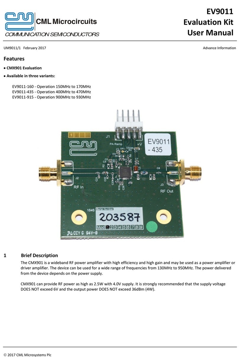
CML Microcircuits EV9011-160 User manual

CML Microcircuits

CML Microcircuits EV9011-160 User manual

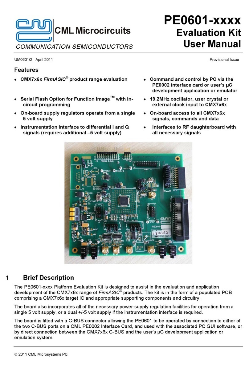
CML Microcircuits PE0601 Series User manual

CML Microcircuits

CML Microcircuits PE0601 Series User manual

Popular Microcontroller manuals by other brands

DF ROBOT YDLIDAR GS2 user manual

DF ROBOT

DF ROBOT YDLIDAR GS2 user manual

ST STM8S Reference manual

ST

ST STM8S Reference manual

HARDKERNEL ODROID-7 user manual

HARDKERNEL

HARDKERNEL ODROID-7 user manual

Acconeer XE132 user guide

Acconeer

Acconeer XE132 user guide

NXP Semiconductors TWR-K70F120M Quick start guides

NXP Semiconductors

NXP Semiconductors TWR-K70F120M Quick start guides

Nuvoton NuMaker M032BTAI user manual

Nuvoton

Nuvoton NuMaker M032BTAI user manual

Infineon XMC4500 series Reference manual

Infineon

Infineon XMC4500 series Reference manual

NEC V850/SC1 user manual

NEC

NEC V850/SC1 user manual

Abov EW8051 Setup guide

Abov

Abov EW8051 Setup guide

Cypress CY8CPROTO-062S3-4343W quick start guide

Cypress

Cypress CY8CPROTO-062S3-4343W quick start guide

Infineon Traveo II Guide

Infineon

Infineon Traveo II Guide

Laird RAMP-AC RF user guide

Laird

Laird RAMP-AC RF user guide

PalmSens EmStat4M manual

PalmSens

PalmSens EmStat4M manual

NEC MuPD78F0132H user manual

NEC

NEC MuPD78F0132H user manual

Microchip Technology SAM E54 Xplained Pro user guide

Microchip Technology

Microchip Technology SAM E54 Xplained Pro user guide

Micromite eXtreme manual

Micromite

Micromite eXtreme manual

Joy-it ARD MEGA2560R3 manual

Joy-it

Joy-it ARD MEGA2560R3 manual

Motorola M68MPBF333 user manual

Motorola

Motorola M68MPBF333 user manual

manuals.online logo
manuals.online logoBrands
  • About & Mission
  • Contact us
  • Privacy Policy
  • Terms and Conditions

Copyright 2025 Manuals.Online. All Rights Reserved.