CMOSTEK CMT2189C Instruction Manual

AN202
V1.0 | Page 1/73
www.cmostek.com
Summary
CMT2189C is a low power, high performance, Flash-based, (G) FSK / OOK RF transmitterchip.It can cover
the 240MHz ~ 960MHz wireless communication band. This chip is embedded with RISC Flash type MCU. It
belongs to the CMOSTEK NextGenRFTM series product. The product series include the short range wireless
communication chips, such as transmitter, receiver, transceiver, SoC and so on.
The part numbers covered by this document are as shown below.
Table1. Part Number Covered by This Document
Part No.
Frequency
Modem
Tx Power
Tx Current
Configuration
Package
CMT2189C
240 - 960MHz
OOK/(G)FSK
+13dBm
32.5mA
Embedded
MCU
SOP14
Note:
The test conditions for the Tx power and Tx current are at 433.92MHz and FSK mode.
AN202
CMT2189C User Guideline
Copyright©ByCMOSTEK

AN202
V1.0 | Page 2/73
www.cmostek.com
Contents
1Chip Architecture Introduction............................................................................................................... 5
1.1 Overall Operation Principle......................................................................................................... 5
1.2IO Pin Description....................................................................................................................... 6
2RF Configuration and Control Mechanism............................................................................................ 8
2.1 Operation Status......................................................................................................................... 8
2.2 Transmitting Control Timing........................................................................................................ 8
2.3 TWI Configuration Bus(Two-wire Interface)........................................................................... 9
2.4 TWI timing Requirement............................................................................................................11
2.5 TWI Timing Enter and Exit........................................................................................................ 12
2.6 TWI Configuration Process....................................................................................................... 13
2.7 Complete Transmission Process .............................................................................................. 14
3Program Memory ................................................................................................................................... 16
4Special Function Register(SFR) ........................................................................................................... 17
4.1 Address Mapping...................................................................................................................... 17
4.1.1 Bank0 SFR........................................................................................................................ 17
4.1.2 Bank1 SFR........................................................................................................................ 18
4.1.3 TMR0(Addr:0x01)......................................................................................................... 19
4.1.4 STATUS(Addr:0x03)..................................................................................................... 19
4.1.5 PORTA(Addr:0x05)....................................................................................................... 20
4.1.6 PORTC(Addr:0x07)...................................................................................................... 21
4.1.7 INTCON(Addr:0x0B)..................................................................................................... 21
4.1.8 PIR1(Addr:0x0C).......................................................................................................... 22
4.1.9 TMR2(Addr:0x11)......................................................................................................... 23
4.1.10 T2CON(Addr:0x12)....................................................................................................... 23
4.1.11 WDTCON(Addr:0x18).................................................................................................. 24
4.1.12 CMCON0(Addr:0x19)................................................................................................... 25
4.1.13 PR0(Addr:0x1A)........................................................................................................... 26
4.1.14 MSCKCON(Addr:0x1B)................................................................................................ 26
4.1.15 SOSCPR(Addr:0x1C/0x1D)......................................................................................... 27
4.1.16 OPTION(Addr:0x81)..................................................................................................... 27
4.1.17 TRISA(Addr:0x85)........................................................................................................ 28
4.1.18 TRISC(Addr:0x87)........................................................................................................ 29
4.1.19 PIE1(Addr:0x8C).......................................................................................................... 29
4.1.20 PCON(Addr:0x8E)........................................................................................................ 30

AN202
V1.0 | Page 3/73
www.cmostek.com
4.1.21 OSCCON(Addr:0x8F)................................................................................................... 30
4.1.22 PR2(Addr:0x92)............................................................................................................ 31
4.1.23 WPUA(Addr:0x95)........................................................................................................ 31
4.1.24 IOCA(Addr:0x96).......................................................................................................... 33
4.1.25 VRCON(Addr:0x99)...................................................................................................... 33
4.1.26 EEDAT(Addr:0x9A)....................................................................................................... 34
4.1.27 EEADR(Addr:0x9B)...................................................................................................... 34
4.1.28 EECON1(Addr:0x9C)................................................................................................... 34
4.1.29 EECON2(Addr:0x9D)................................................................................................... 35
4.1.30 Configuration Register UCFGx ......................................................................................... 35
4.1.31 PCL and PCLATH.............................................................................................................. 37
4.1.32 INDFand FSR Register ..................................................................................................... 38
5MCU SystemClock Source.................................................................................................................... 39
5.1 Clock Source Mode................................................................................................................... 39
5.1.1 Internal Clock Mode .......................................................................................................... 40
5.1.2 Frequency Select Bit(IRCF)......................................................................................... 40
5.1.3 Clock Switch Timing of HFINTOSC and LFINTOSC......................................................... 40
5.2 Clock Switching......................................................................................................................... 41
5.2.1 System Clock Select Bit (SCS) ......................................................................................... 41
5.2.2 Oscillator Start-up Timeout Status(OSTS) Bit................................................................... 42
5.3 Two-Speed Clock Start-up Mode.............................................................................................. 42
5.3.1 Two-Speed Start-up Mode Configuration.......................................................................... 42
5.3.2 Two-Speed Start-up Sequence......................................................................................... 43
5.4 Fail-Safe Clock Monitor............................................................................................................. 43
5.4.1 Fail-Safe Detection............................................................................................................ 43
5.4.2 Fail-Safe Operation........................................................................................................... 43
5.4.3 Fail-Safe Condition Being Cleared.................................................................................... 44
5.4.4 Reset or Wake-up from Sleep........................................................................................... 44
6Reset Timing........................................................................................................................................... 45
6.1 Power-on Reset (POR)............................................................................................................. 46
6.2 External Reset (MCLR)............................................................................................................. 46
6.3 Power-up Timer (PWRT)........................................................................................................... 46
6.4 Brown-out Reset (BOR(LVR)).............................................................................................. 47
6.5 Error Instruction Reset.............................................................................................................. 47
6.6 Timeout Action .......................................................................................................................... 47
7BOOT....................................................................................................................................................... 50

AN202
V1.0 | Page 4/73
www.cmostek.com
8Watchdog Timer..................................................................................................................................... 51
9Timer0 ..................................................................................................................................................... 52
9.1 Timer0 Introduction................................................................................................................... 52
9.2 Timer0 Timer Mode................................................................................................................... 52
9.3 Timer0 Counter Mode............................................................................................................... 52
9.3.1 Software Configuring Prescaler Circuit............................................................................. 53
9.3.2 Timer0 Interrupt................................................................................................................. 54
9.3.3 Drive Timer0 with an External Clock ................................................................................. 54
10 Timer2 ..................................................................................................................................................... 55
11 Comparator............................................................................................................................................. 57
12 Data EEPROM......................................................................................................................................... 58
13 Clock Measurement............................................................................................................................... 59
14 Interrupt Mode........................................................................................................................................ 60
14.1 INT Interrupt.............................................................................................................................. 60
14.2 PORTA Level Change Interrupt ................................................................................................ 61
14.3 Interrupt Response ................................................................................................................... 61
14.4 Context Saving During Interrupts.............................................................................................. 63
15 MCU Sleep Saving Mode....................................................................................................................... 64
15.1 Wake-up Mode.......................................................................................................................... 64
15.2 Watchdog Wake-up................................................................................................................... 64
16 I/O Port .................................................................................................................................................... 65
16.1 PORTA Port and TRISA Register.............................................................................................. 65
16.2 Other Functions of the Port....................................................................................................... 65
16.2.1 Weak Pull-Up .................................................................................................................... 65
16.2.2 Interrupt-On-Change......................................................................................................... 65
16.3 Port Description ........................................................................................................................ 66
16.3.1 PORTA<2:0>..................................................................................................................... 66
16.3.2 PORTA5 ............................................................................................................................ 67
16.3.3 PORTC4 and PORTC2 ..................................................................................................... 69
17 Instruction Set List ................................................................................................................................ 70
18 Document Modification Record............................................................................................................ 72
19 Contact Information............................................................................................................................... 73

AN202
V1.0 | Page 5/73
www.cmostek.com
1 Chip Architecture Introduction
1.1 Overall Operation Principle
CMT2189C is a MCU integrated with RF transmiterchip. It uses the crystal oscillator to provide the reference
frequency and digital clock for PLL, supports the OOK modulation which data rate is from 1Kbps to 30Kbps
and the (G) FSK modulationwhich data rate is from 1Kbps to 100Kbps, and supports the status control based
on the MCU program. It is suitable for all kinds of low power transmitting applications.
LDOs
PFD/CP
Fractional-N
DIV
Interface and Digital Logic
EEPROM
Loop Filter
Modulator Ramp
Control
VCO
XOSC
AVDD GND
XTAL
RFCLK
RFDAT
PAP
POR Bandgap
PA
CPU
Program ROM
2K * 14Bit
Data EEPROM
256 * 8Bit
TMR/WDT
IO
CMP
RSTC/OST/
PWRT/BOOT CLKC
(IRCCK)
SFR
SRAM
128 * 8Bit
CFG
DVDD
PA0 PA1 PA2 PA5 PC4 PC2
TWI
PAN
Figure 1-1. CMT2189C System Architecture
The chip uses the PLL+PA architecture to achieve the Sub-GHz wireless transmitting function. It supports the
direct mode that the data inputs and transmits from the antenna. The processed data is sent to the modulator,
the modulator controls PLL and PA, and the data is modulated by OOK/ (G) FSK and transmitted out.
The MCU of the chip controls the RF part by the Two-wire interface, and can achieve various status switching,
mode selection and low power control.

AN202
V1.0 | Page 6/73
www.cmostek.com
1.2 IO Pin Description
AVDD
GND
PAP
PAN
PC2/RFCLK
PA5/MCLRB
PA2/T0CKI/INT/C1OUT
DVDD
GND
XTAL
PA1/C1IN-/ICSPDAT
PA0/C1IN+/ICSPCLK
1
2
3
4
5
6
7
9
14
13
12
11
10
8
PC4/C2OUT/RFDAT
GND
Figure 1-2. CMT2189C Pin Top View
Table 1-2. CMT2189C SOP14 Package Pin Description
Pin No.
Name
Type
I/O
Function Description
1
AVDD
Analog
I
Chip RF power supply positive pole
2
GND
Digital
I
Chip power supply ground
3
PAP
Analog
O
Chip PA output +
4
PAN
Analog
O
Chip PA output -
5
PC2/RFCLK
Digital
IO
PC2
General IO
RFCLK
RF communication TWI bus clock
line,CLK,internal pull-up
6
PA5/MCLRB
Digital
I
PA5
Only as input, support IOC
MCLRB
External reset input, can be configured
aspull-up
7
PA2/T0CKI/INT/C1OUT
Digital
IO
PA2
General IO, support IOC, can be
configured aspull-up
T0CKI
Timer0 clock source input(Max=4MHz)
INT
External interrupt input
C1OUT
Comparator1 output
8
PA0/C1IN+/ICSPCLK
Digital
IO
PA0
General IO, support IOC, can be
configured as pull-up
C1IN+
Comparator 1 input +
ICSPCLK
Debug/ burning mode, serial port clock
signal
9
PA1/C1IN-/ICSPDAT
Digital
O
PA1
General IO, support IOC, can be
configured as pull-up

AN202
V1.0 | Page 7/73
www.cmostek.com
Pin No.
Name
Type
I/O
Function Description
C1IN-
Comparator1 input -
ICSPDAT
Debug/ burning mode, serial port data
signal
10
GND
Digital
I
Chip power supply ground
11
DVDD
Digital
I
Chip digital power supply positive pole
12
PC4/C2OUT/RFDAT
Digital
IO
PC4
General IO
C2OUT
Comparator2 output
RFDAT
RF communication TWI bus data line,
DAT, and also data transmitting pin,
internal pull-down
13
GND
Digital
I
Chip power supply ground
14
XTAL
Analog
I
RF part crystal oscillator input
Note:
The two comparators are integrated within the MCU, but the internal comparator can not be used because
they have the package terminals and some of them are reused to the RF part at the same time. However, in
the initialization process, MCU needs to turn off the comparator function and set its corresponding pin as the
digital IO to avoid affecting the work of other functions.

AN202
V1.0 | Page 8/73
www.cmostek.com
2 RF Configuration and Control Mechanism
2.1 Operation Status
The RF part of CMT2189C has four main operation statuses: SLEEP, XO-STARTUP, TUNE and TRANSMIT.
SLEEP
In this status, the whole module of RF is in a low power status, and the internal related circuits are closed, and
the consumption is only 20nA (only for the RF part).
XO-STARTUP
In the sleep status, the RF part will start up the oscillator when it is triggered by the RFDAT edge (rising edge).
TUNE
This status is that the frequency synthesizer tunes the oscillation frequency to the desired value.
TRANSMIT
After the frequency synthesizer tuned the frequency to the desired value, the transmitted data is input through
RFDAT to control the PA transmitting.In the transmitting process, if the time RFDAT holds a low level is longer
than tSTOP setting time (TSTOP is not unique, and can be selected. the specifics refer to RFPDK and the
following chapters), the RF part will automatically stop the transmitting and enter the SLEEP status.
Table 2-1.Status Switching Time
Parameter
Symbol
Min
Typ
Max
Unit
XTAL Startup Time [1]
tXTAL
400
us
Time to Tune to Desired Frequency
tTUNE
370
us
Hold Time After Rising Edge
tHOLD
10
ns
Time to Stop the Transmission[2]
tSTOP
2
90
ms
Notes:
This parameter mainly depends on the crystal itself. The range is from 2 ms to 9ms (step unit is 1ms, only
for FSK), and from 20ms to 90ms (step unit is 10ms).
2.2 Transmitting Control Timing
The RF transmitting of CMT2189C is mainly controlled by setting RFDAT (RFCLK holds the high level in the
process of transmitting), and the specific timing diagram is as follows:

AN202
V1.0 | Page 9/73
www.cmostek.com
SLEEP
SLEEP TRANSMIT
STATE
PA out RF Signals
tSTOPtXTAL
TUNEXO-STARTUP
tTUNE
PC4/RFDAT Valid Transmitted DataDon’t Care
01
tHOLD
0
Rising Edge
Figure 2-1. Transmitting Timing Diagram
2.3 TWI Configuration Bus(Two-wire Interface)
CMT2189C’s internal integrated transmitting circuit is the same as CMT2119A. It supports any frequency of
Sub-G ranging from 240MHz ~ 960MHz, and it also uses the TWI bus configuration interface.Through the
TWI interface, users can allow CMT2189C to change the frequency(frequency hopping), transmitting power
(amplitude), modulation mode (OOK, FSK, GFSK) by programming.
The specific operation steps are: Select CMT2119A at the RFPDK interface at first; set the required frequency,
modulation mode and other parameters; click Export to generate the configuration parameters, as shown
below:
Figure2-2. RFPDK Setting Interface
AN202
V1.0 | Page 10/73
www.cmostek.com
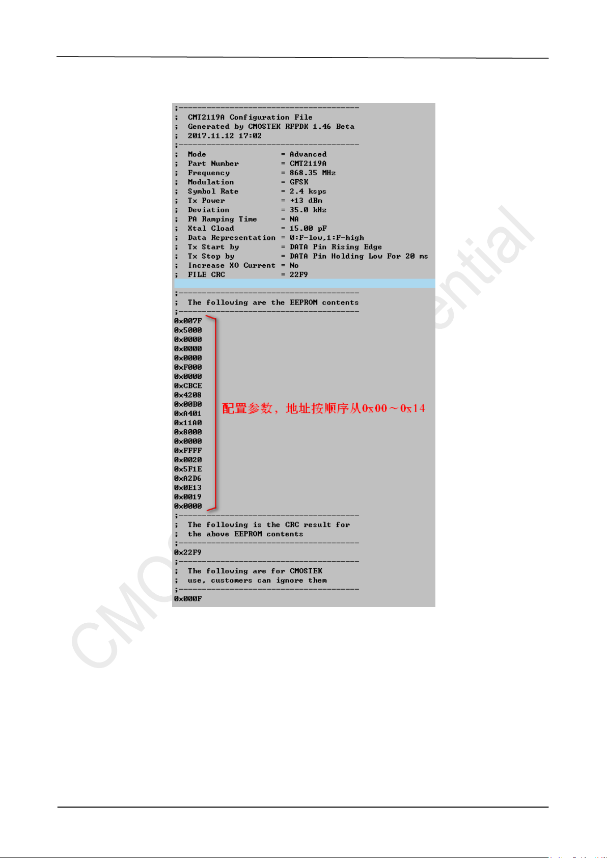
Open the exp file, as shown below:
Figure 2-3. Export the parameter file
Configure the generation parameters to the RF of CMT2189C according to the software lookup mode, and
then control the transmission according to the controlling sequence (see Section2.2).

AN202
V1.0 | Page 11/73
www.cmostek.com
2.4 TWI timing Requirement
Table 2-2. TWI timing Requirement
Parameter
Symbol
Conditions
Min
Typ
Max
Unit
Digital Input Level High
VIH
0.8
VDD
Digital Input Level Low
VIL
0.2
VDD
CLK Frequency
FCLK
10
1,000
kHz
CLK High Time
tCH
500
ns
CLK Low Time
tCL
500
ns
CLK Delay Time
tCD
CLK delay time for the first falling
edge of the TWI_RST command,
see Figure 2-6
20
15,000
ns
DATA Delay Time
tDD
The data delay time from the last
CLK rising edge of the TWI
command to the time DATA return
to default status
15,000
ns
DATA Setup Time
tDS
From DATA change to CLK falling
edge
20
ns
DATA Hold Time
tDH
From CLK falling edge to DATA
change
200
ns
tDS tDHtCH tCL
RFCLK
RFDAT
Figure 2-4. TWI Timing Diagram
RFCLK
RFDAT W/R A51
A4 A2 A1A3 A0 D6 D5D7 D4 D2 D1D3
X
tDD
Default
State
D0
Figure 2-5. TWI 16-bit Command Timing Diagram
A group of TWI commands are composed of 16-bit data sent by RFCLK and RFDAT. The above diagram is a
set of standard command timing format. In the high 8-bit data, the first bit is fixed to 1. Bit6 is a read/write
distinction bit, "0" represents the write operation. "1" represents the read operation. The latter 6-bit is the
register address of the operation. The low 8-bit data is the writing value or reading value of the operation
register.

AN202
V1.0 | Page 12/73
www.cmostek.com
Among them, TWI_WRREG represents the write operation of the register; TWI_RDREG represents the read
operation of the register, detailed as follows:
Table 2-3. TWI_WRREG and TWI_RDREG
Command
Description
TWI_WRREG
TWI write operation, Pseudo instruction format: TWI_WRREG(XX,YY) represents a set
of 16 clock data streams,0b’10xx xxxx yyyy yyyy,where 0b 'XX XXXX is the address
of the target operation register, the range is from 0x00 to 0x3F; 0b 'yyyy yyyy is the
value that needs to be written to the target register, and the range is from 0x00 to 0xFF.
For example, TWI_WRREG (0x12, 0xAA), the data stream is 0x92AA.
TWI_RDREG
TWI read operation, Pseudo instruction format: TWI_RDREG(XX, ZZ) represents a set
of 16 clock data streams,0b’11xx xxxx zzzz zzzz,where 0b 'XX XXXX is the address
of the target operation register, and the range is from 0x00 to 0x3F; 0b 'Zzzz Zzzz is the
read value of the target register, and the range is from 0x00 to 0xFF.
For example: TWI_RDREG (0x2A, DAT), the high 8-bit data stream is 0xEA, and the
low 8-bit data stream is the actual read value.
2.5 TWI Timing Enter and Exit
In the TWI bus, RFDAT is the data line of the TWI, and it is also the data line of Tx. When the RFDAT edge
changes, in order to distinguish between entering the Tx status or the TWI configuration mode, users need to
access to the TWI configuration mode by a specific operation.
Here are three sets of special commands:
SOFT_RST:Reset command of RF part circuit
TWI_RST:TWI bus reset timing. Enter the TWI configuration mode after operation.
TWI_OFF:TWI bus closing timing. Exit the TWI configuration mode after operation.
Table 2-4. TWI Command Description
Command
Descriptions
TWI_RST
Hold RFDAT continuously to low level (Not allowed to be pulled up in the middle). RFCLK
sends 32 clock signals continuously, which is 4 bytes of 0x00, and then sends a set of 0x8D00
command. Thereafter RF enters the TWI configuration mode, the RFDAT change will no longer
trigger the Tx status.
TWI_OFF
In the TWI configuration mode, send a set of 0x8D02 command. Thereafter exit the TWI
configuration mode, the RFDAT change will trigger the Tx status.
SOFT_RST
At any time, when sending a set of 0xBD01 command, RF part executes reset. After reset, RF
part enters the SLEEP mode directly to wait for the RFDAT edge to trigger the Tx status.

AN202
V1.0 | Page 13/73
www.cmostek.com
CLK
32 clock cycles
……
16 clock cycles
DATA 0x8D000 0
Figure 2-6. TWI_RST Command Timing Diagram
DATA
CLK
16 clock cycles
0x8D02 (TWI_OFF)
…tDD
Default
State
Figure 2-7. TWI_OFF Command Timing Diagram
DATA
CLK
16 clock cycles
0xBD01 (SOFT_RST)
…tDD
Default
State
Figure 2-8. SOFT_RST Command Timing Diagram
2.6 TWI Configuration Process
TWI configuration process is as follows:
TWI_RST SOFT_RST
(wait 1 ms before moving to Step-3) TWI_WRREG(0x02, 0x78)
(1) - TWI_WRREG(0x2F, 0x80)
(2) - TWI_WRREG(0x35, 0xCA)
(3) - TWI_WRREG(0x36, 0xEB)
(4) - TWI_WRREG(0x37, 0x37)
(5) - TWI_WRREG(0x38, 0x82)
(1) - TWI_WRREG(0x12, 0x10)
(2) - TWI_WRREG(0x12, 0x00)
(3) - TWI_WRREG(0x24, 0x07)
(4) - TWI_WRREG(0x1D, 0x20)
(1) - TWI_WRREG(0x18, Addr)
(2) - TWI_WRREG(0x19, Low_data)
(3) - TWI_WRREG(0x1A, High_data)
(4) - TWI_WRREG(0x25, 0x01)
TWI_OFF TRANSMISSION TWI_WRREG( 0x02, 0x7F)
1 2 3
3 4 5 6
6 7 8
Step-1 Step-2 Step-3
Step-4 Step-5
Step-7 Step-8 Step-9
Step-6
Figure 2-9. TWI Configuration Process Diagram

AN202
V1.0 | Page 14/73
www.cmostek.com
Note:
1. After completing the SOFT_RST at the Step2, it needs to wait for 1ms before the Step3 operation.
2. Step6 is a configuration register operation, which is not a direct write operation, but an indirect operation
through internal circuit. So writing a register must repeat the process of Step6:
3. Write the target register address to 0x18.
4. The low 8-bit of the 16-bit data is written to 0x19.
5. The high 8-bit of the 16-bitdata is written to 0x1A.
6. Write 0x01 to the register 0x25, triggering the operation will take effect.
For example: The value to be written is 0xC3F6. The target address is 0x02. According to Step6, the process
is as follows:
TWI_WRREG(0x18, 0x02); // Write the Addr 0x02 to register 0x18
TWI_WRREG(0x19, 0xF6); // Write the Low_data 0xF6 to register 0x19
TWI_WRREG(0x1A, 0xC3); // Write the High_data 0xC3 to register 0x1A
TWI_WRREG(0x25, 0x01); //Trigger the overwriting to the feature register, the writing process
completes
In the configuration above, you can repeat the Step6 process in the Step6 stage, and configure all the
registers that need to be. When the user needs to do a read operation to confirm whether the write operation
is correct, the read operation is also indirect, similar to the Step6 process.
For example: The read address is 0x02, the process is as follows:
TWI_WRREG(0x18, 0x02); // Write the Addr 0x02 to register 0x18
TWI_RDREG(0x1B, DATAL); // Read theLow_data from 0x1B and store it in the DATAL variable
TWI_RDREG(0x1C, DATAH); // Read the High_data from 0x1C and store it in the DATAH variable
But users need to notice that the read operation is the same as the write operation. The front Step1 to Step5
still needs to be executed, and reading and writing can be done in the Step6 stage.
2.7 Complete Transmission Process
A complete transmission process includes the parameter configuration, transmission, resetting TWI bus and
RF part, as shown in the following figure:
One Transmission Cycle
(1 ) - TWI_RST
(2 ) - SOFT_RST
(1 ) - TWI_RST
(2 ) - SOFT_RST
TRANSMISSION
Reset TWI One Transmission Cycle
(1 ) - TWI_RST
(2 ) - SOFT_RST
TRANSMISSION
(1 ) - TWI_RST
(3 ) - TWI_OFF
(2 ) - Step2 to Step6
(1 ) - TWI_RST
(3 ) - TWI_OFF
(2 ) - Step2 to Step6
Figure 2-10. Configure Parameters for Each Transmission
The advantage of configuring parameters for each transmission is reliable. At the same time, after completing

AN202
V1.0 | Page 15/73
www.cmostek.com
the transmission, resetting the TWI bus and RF part to allow RF part to enter the low power status of sleep.
The disadvantage is that users have to do a cumbersome configuration process every time.
Note:
Users may ask if they can only execute configuration parameters once after power-up. This method is to hold
the RFDAT to low and continue until the end of the tSTOP time, as shown in the following figure:
The 1st Transmission Cycle
(1 )- TWI_RST
(2 )- SOFT_RST
Hold RFDAT = 0
Wait for tSTOP
TRANSMISSION
Reset TWI One Transmission Cycle
TRANSMISSION
(1 ) - TWI_RST
(3 ) - TWI_OFF
(2 ) - Step2 to Step6 Hold RFDAT = 0
Wait for tSTOP
Figure 2-11. Only Execute Configuration Parameters Once
But this method is unable to achieve the low power consumption, because users trigger the RF internal
register to save temporarily the configuration content, these temporary storage functions need to consume a
certain amount of power (100uA or so); unless users do not execute the configuration mechanism, or do not
use temporarily saving register (i.e. there is nothe process from Step2 to Step6, shown as below). Users only
rely on the RF internal burning parameters as theconfiguration parameters.
One Transmission Cycle
(1) - TWI_RST
(2) - SOFT_RST
(1) - TWI_RST
(2) - TWI_OFF
(1) - TWI_RST
(2) - SOFT_RST
TRANSMISSION
Reset TWI One Transmission Cycle
(1) - TWI_RST
(2) - TWI_OFF
(1) - TWI_RST
(2) - SOFT_RST
TRANSMISSION
Figure 2-12. Burning Way Transmission Process (Not configuring the register)

AN202
V1.0 | Page 16/73
www.cmostek.com
3 Program Memory
The program address register is 13-bit, supports for access to 8K Bytes space (0x0000~ 0x1FFF) in
maximum. But the actual chip memory is 2K Words, plus 4 additional user configuration banks (UCFGx) and
factory configuration banks (FCFGx), the total is 64 Words.They are made up of EEPROM. Among them, the
0~0x7FF is the main program bank, the 0x800~0x1FFF is unimplemented bank which isreserved.The user
and factory configuration information bank is 0x2000~0x203F.
UCFG0
UCFG1
UCFG2
...
...
FCFG0
FCFG1
FCFG2
...
INFOx
...
...
0x2000
0x2001
0x2002
.
.
.
0x2010
0x2011
0x2012
0x2020
.
.
0x203F
.
.
程序区
保留
不可用
信息区
0x000
0x7FF
0x1FFF
0x2000
0x203F
Figure 3-1. Program Space Address Mapping

AN202
V1.0 | Page 17/73
www.cmostek.com
4 Special Function Register(SFR)
4.1 Address Mapping
4.1.1 Bank0 SFR
Table 4-1. Bank0 Register List
ADDR
Name
Bit7
Bit6
Bit5
Bit4
Bit3
Bit2
Bit1
Bit0
POR reset
0
INDF
Access the data memory by using the content of FSR(non physical registers)
xxxx xxxx
1
TMR0
Timer0<7:0>
xxxx xxxx
2
PCL
Program Counter<7:0>
0000 0000
3
STATUS
-
-
PAGE
/TF
/PF
Z
HC
C
--01 1xxx
4
FSR
Indirect Data Memory Address Pointer
5
PORTA
PA7
PA6
PA5
PA4
PA3
PA2
PA1
PA0
00x0 0000
6
- - - - ----
7
PORTC
PC7
PC6
PC5
PC4
PC3
PC2
PC1
PC0
0000 0000
8
- - - - ----
9
- - - - ----
A
PCLATH
-
-
-
Program Counter<13:8>
---0 0000
B
INTCON
GIE
PEIE
T0IE
INTE
PAIE
T0IF
INTF
PAIF
0000 0000
C
PIR1
EEIF
CKMEAIF
-
C2IF
C1IF
OSFIF
TMR2IF
-
00-0 000-
D
- - - - ----
E
- - - - ----
F
- - - - ----
10
- - - - ----
11
TMR2
Timer2<7:0>
0000 0000
12
T2CON
-
TOUTPS<3:0>
TMR2ON
T2CKPS<1:0>
-000 0000
13
- - - - ----
14
- - - - ----
15
- - - - ----
16
- - - - ----
17
- - - - ----
18
WDTCON
-
-
-
WDTPS<3:0>
SWDTEN
---0 1000
19
CMCON0
C2OUT
C1OUT
C2INV
C1INV
CIS
CM<2:0>
0000 0000
1A
PR0
PR0<7:0>
1111 1111
1B
MSCKCON
-
-
-
SLVREN
-
CKMAVG
CKCNTI
-
---0 -00-
1C
SOSCPPRL
SOSCPR<7:0>
1111 1111
1D
SOSCPRH
-
-
-
-
SOSCPR<11:8>
---- 1111
1E
- - - - ----
1F
- - - - ----
20-7F
Bank0’s SRAM, which is the general RAM of 96Byte.
xxxx xxxx

AN202
V1.0 | Page 18/73
www.cmostek.com
4.1.2 Bank1 SFR
Table 4-2. Bank1 Register List
ADDR
Name
Bit7
Bit6
Bit5
Bit4
Bit3
Bit2
Bit1
Bit0
POR reset
80
INDF
Access the data memory by using the content of FSR (non physical registers)
xxxx xxxx
81
OPTION
/PAPU
INTEDG
T0CS
T0SE
PSA
PS2
PS1
PS0
1111 1111
82
PCL
Program Counter<7:0>
0000 0000
83
STATUS
-
-
PAGE
/TF
/PF
Z
HC
C
--01 1xxx
84
FSR
Indirect Data Memory Address Pointer
85
TRISA
TRISA<7:6>
--
TRISA<4:0>
11x1 1111
86
---- - - - -
87
TRISC
TRISC<7:0>
1111 1111
88
---- - - - -
89
---- - - - -
8A
PCLATH
-
-
-
Program Counter<13:8>
---0 0000
8B
INTCON
GIE
PEIE
T0IE
INTE
PAIE
T0IF
INTF
PAIF
0000 0000
8C
PIE1
EEIE
CKMEAIE
-
C2IE
C1IE
OSFIE
TMR2IE
-
00-0 000-
8D
---- - - - -
8E
PCON
/POR
/BOR
---- --qq
8F
OSCCON
LFMOD
IRCF[2:0]
OSTS
HTS
LTS
SCS
0101 x000
90
---- - - - -
91
0000 0000
92
PR2
PR2[7:0], Timer2 period register
1111 1111
93
---- - - - -
94
---- - - - -
95
WPUA
WPUA<7:6>
-
WPUA<4:0>
11-1 1111
96
IOCA
IOCA<7:0>
---- - - - -
97
---- - - - -
98
---- - - - -
99
VRCON
VREN
-
VRR
-
VR<3:0>
0-0- 0000
9A
EEDAT
EEDAT<7:0>
0000 0000
9B
EEADR
EEADR<7:0>
0000 0000
9C
EECON1
-
-
WREN3
WREN2
WRERR
WREN1
-
RD
--00 x0-0
9D
EECON2
-
-
-
-
-
-
-
WR
---- ---0
9E
---- - - - -
9F
---- - - - -
A0-BF
Bank1's SRAM, which is the general RAM of 32Bytes.
xxxx xxxx
C0-EF
---- - - - -
F0-FF
SRAM. Access Bank0’s 0x70~0x7F.
xxxx xxxx
Note:
1. INDF is not a physical register.
2. The gray part is unimplemented, please do not access.
3. "-" indicates that it is unimplemented; the unimplemented register bits can not be used or written as1. It is

AN202
V1.0 | Page 19/73
www.cmostek.com
used for subsequent chip upgrading.
4.1.3 TMR0(Addr:0x01)
Table 4-3. TMR0 Register
Name
Bit7
Bit6
Bit5
Bit4
Bit3
Bit2
Bit1
Bit0
TMR0
Timer0<7:0>,Count result register
Reset
X
X
X
X
X
X
X
X
Type
RW
4.1.4 STATUS(Addr:0x03)
Table 4-4. STATUS Register
Name
Bit7
Bit6
Bit5
Bit4
Bit3
Bit2
Bit1
Bit0
STATUS
-
-
PAGE
/TF
/PF
Z
HC
C
Reset
-
-
0
1
1
X
X
X
Type
-
-
RW
R
R
RW
RW
RW
Table 4-5. STATUS Bit Function Description
Bit
Name
Function
7:6
-
No function, read as “0”
5
PAGE
Register Bank Select bit:
0 = BANK0(00h-7Fh)
1 = BANK1(80h-FFh)
4
/TF
Time-out bit
1 = After power-up, CLRWDT instruction or SLEEP instruction
0 = AWDT time-out occured.
3
/PF
Power-down bit
1 = After power-up or by the CLRWDT instruction
0 = By executation of the SLEEP instruction
2
Z
Zero bit
1 = The result of an arithmetic or logic operation is zero
0 = The result of an arithmetic or logic operation is not zero
1
HC
Half-carry/bit(ADDWF、ADDLW、SUBLW、SUBWF instructions)
1 = A carry/ from the 4th low-order bit of the result occurred
0 = No carry/ from the 4th low-order bit of the result occurred
0
C
Carry/ bit(ADDWF、ADDLW、SUBLW、SUBWF instructions)
1 = A carry/ from the Most Significant bit of the result occurred
0 = No carry/ from the Most Significant bit of the result occurred

AN202
V1.0 | Page 20/73
www.cmostek.com
Table 4-6. FlagSituation in Each ResetStatus
/TF
/PF
Condition
1
1
Power on or low voltage reset
0
u
WDT reset
0
0
WDT wake-up
u
u
MCLR reset under the normal operation
1
0
MCLR reset in the sleep status
Note:
1. The Status register can also be the destination register for any instruction, like any other register. If
the Status register is the destination register for an instruction that affects the Z, HC, or C bit, then
the “write”to these three bits is disabled. These bits are set to 1 or cleaned according to the device
logic.Therefore, the result of an instruction with the Status register as destination may be different
than intended.
2. It is suggested that only using the BCR, BSR, SWAPR and STR instructions to change the status
register.
4.1.5 PORTA(Addr:0x05)
Table 4-7. PORTA Register
Name
Bit7
Bit6
Bit5
Bit4
Bit3
Bit2
Bit1
Bit0
PORTA
PA7
PA6
PA5
PA4
PA3
PA2
PA1
PA0
Reset
X
X
X
X
X
X
X
X
Type
RW
RW
R
RW
RW
RW
RW
RW
Table 4-8. PORTA Bit Function Description
Bit
Name
Function
7
PA7
PORTA7 data
6
PA6
PORTA6 data
5
PA5
PORTA5 only acts as the input.There is no corresponding output data register.
4
PA4
PORTA4 data
3
PA3
PORTA3 data
2
PA2
PORTA2 data
1
PA1
PORTA1 data
0
PA0
PORTA0 data
Table of contents
Other CMOSTEK Transmitter manuals


