CMOSTEK NextGenRF CMT2189B User manual

AN201
Rev 1.5 | 1/91
www.cmostek.com
Overview
The CMT2189B is a low power, high performance, Flash-based, OOK RF transmitter chip embedded with the RISK MCU , which
covers a wireless communication band of 240 - 960 MHz. The product is a part of the CMOSTEK NextGenRFTM product family
which covers a complete product line consisting of transmitters, receivers, transceiver, etc.
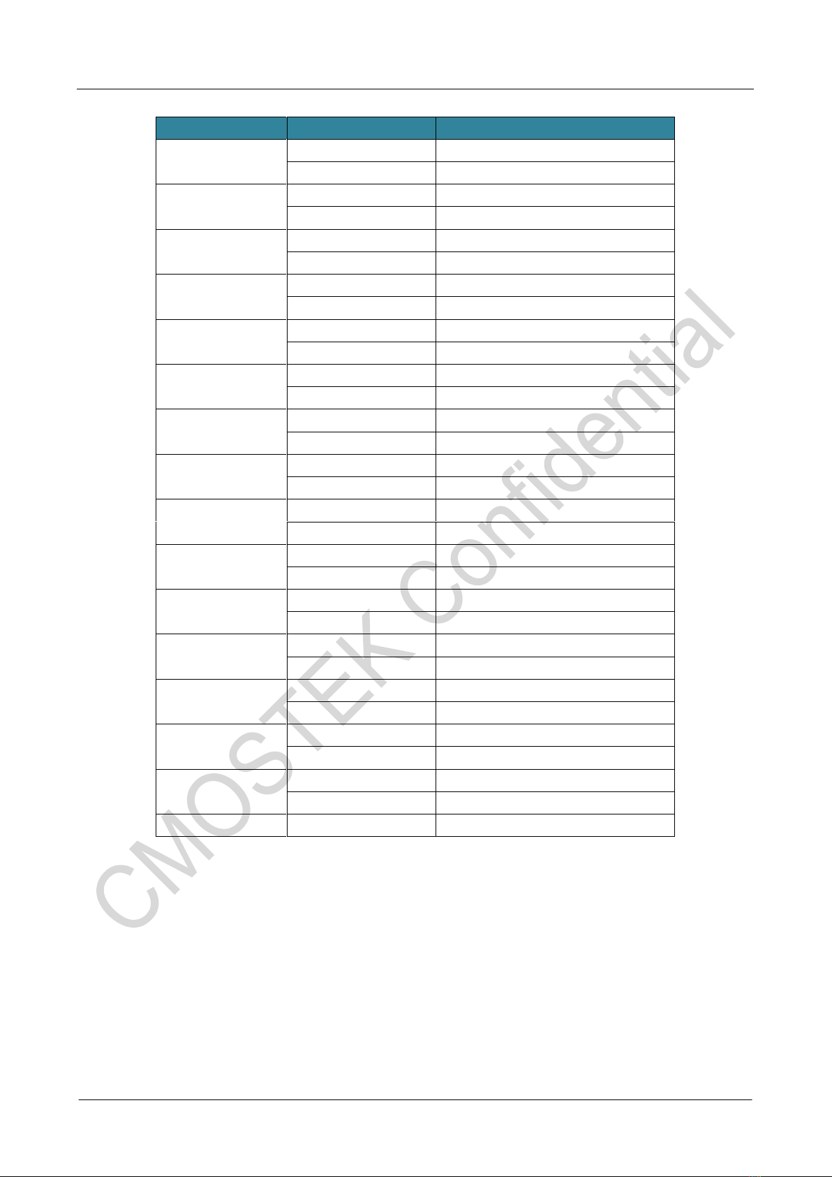
The product models covered in this document are shown in the table below.
Table 1. Product Models Covered in This Document
Product
Model
Frequency
Range
Modulation
Method
Tx Power
Tx Current
Configuration
Package
CMT2189B
240 - 960MHz
OOK
+13 dBm
17.5 mA
Embedded
MCU
SOP14
Notes:
The test condition for the Tx power and Tx current is: 433.92 MHz, CW mode (always in the Tx carrier mode), Tx mode of Duty 50%
and Tx current of 8.5 mA.
AN201
CMT2189B User Guide
Copyright ©By CMOSTEK

AN201
Rev 1.5 | 2/91
www.cmostek.com
Table of Contents
1Chip Architecture.............................................................................................................................. 5
1.1 Overall Operating Principle ................................................................................................................................ 5
1.2 IO Pin Description ..............................................................................................................................................5
2RF Part Configuration and Control Mechanism............................................................................ 8
2.1 Operating Mode..................................................................................................................................................8
2.2 Simple Operating Mode...................................................................................................................................... 8
2.3 Advanced Configuration Mode...........................................................................................................................9
2.4 SPI Interface Timing......................................................................................................................................... 10
2.5 RF Configuration Parameter ............................................................................................................................ 11
2.6 Configuration Register...................................................................................................................................... 14
2.7 Packet Related Register................................................................................................................................... 15
2.7.1 Tx Rate ....................................................................................................................................................16
2.7.2 Hardware Packet Format.........................................................................................................................17
2.7.3 Preamble .................................................................................................................................................18
2.7.4 Head/Sync...............................................................................................................................................18
2.7.5 Addr/ID.....................................................................................................................................................19
2.7.6 Key Value.................................................................................................................................................21
2.7.7 LBD Status Configuration ........................................................................................................................22
2.7.8 Stop Bit Configuration..............................................................................................................................24
2.7.9 Pause/Interval Configuration....................................................................................................................25
2.7.10 Tcycle Configuration.................................................................................................................................25
2.8 State and Function Register............................................................................................................................. 27
2.8.1 Soft Reset................................................................................................................................................27
2.8.2 Operating State and State Switching.......................................................................................................27
2.8.3 Operating State Query.............................................................................................................................28
2.9 Hardware Packet Tx Mode............................................................................................................................... 29
2.9.1 Power-up Initialization..............................................................................................................................29
2.9.2 Tx Process...............................................................................................................................................29
2.10 Pass-through Tx Mode (Advanced Configuration Mode).................................................................................. 31
2.10.1 Power-up initialization..............................................................................................................................31
2.10.2 Tx Process...............................................................................................................................................31
2.10.3 Related Register......................................................................................................................................31
3Program Memory ............................................................................................................................ 33
4Special Function Register(SFR).................................................................................................... 34
4.1 Address Mapping ............................................................................................................................................. 34
4.1.1 Bank0 SFR ..............................................................................................................................................34
4.1.2 BANK1 SFR.............................................................................................................................................35
4.1.3 TMR0 (Addr:0x01) ...................................................................................................................................36
4.1.4 STATUS (Addr:0x03)................................................................................................................................36
4.1.5 PORTA (Addr:0x05) .................................................................................................................................38
4.1.6 PORTC(Addr:0x07).............................................................................................................................38
4.1.7 INTCON (Addr:0x0B)...............................................................................................................................39
4.1.8 PIR1 (Addr:0x0C).....................................................................................................................................40
4.1.9 TMR2 (Addr:0x11)....................................................................................................................................41
4.1.10 T2CON (Addr:0x12).................................................................................................................................41

AN201
Rev 1.5 | 3/91
www.cmostek.com
4.1.11 WDTCON (Addr:0x18).............................................................................................................................42
4.1.12 CMCON0 (Addr:0x19)..............................................................................................................................42
4.1.13 PR0 (Addr:0x1A)......................................................................................................................................43
4.1.14 MSCKCON (Addr:0x1B) ..........................................................................................................................44
4.1.15 SOSCPR (Addr:0x1C/0x1D)....................................................................................................................44
4.1.16 OPTION (Addr:0x81) ...............................................................................................................................45
4.1.17 TRISA (Addr:0x85)...................................................................................................................................46
Table 4-32. TRISA Bit Function Description ...................................................................................... 46
4.1.18 TRISC (Addr:0x87) ..................................................................................................................................46
4.1.19 PIE1(Addr:0x8C).................................................................................................................................47
4.1.20 PCON(Addr:0x8E)...............................................................................................................................48
4.1.21 OSCCON (Addr:0x8F).............................................................................................................................48
4.1.22 PR2 (Addr:0x92)......................................................................................................................................49
4.1.23 WPUA (Addr:0x95)...................................................................................................................................50
4.1.24 IOCA (Addr:0x96).....................................................................................................................................50
4.1.25 VRCON (Addr:0x99)................................................................................................................................50
4.1.26 EEDAT(Addr:0x9A).............................................................................................................................51
4.1.27 EEADR(Addr:0x9B).............................................................................................................................51
4.1.28 EECON1(Addr:0x9C)..........................................................................................................................51
4.1.29 EECON2 (Addr:0x9D)..............................................................................................................................52
4.1.30 Configuration Register UCFGx ................................................................................................................52
4.1.31 PCL and PCLATH....................................................................................................................................54
4.1.32 INDF and FSR Register...........................................................................................................................55
5System Clock Source..................................................................................................................... 56
5.1 Clock Source Mode.......................................................................................................................................... 56
5.2 External Clock Mode........................................................................................................................................ 57
5.2.1 EC Mode..................................................................................................................................................57
5.2.2 LP and XT Modes ....................................................................................................................................57
5.3 Internal Clock Mode ......................................................................................................................................... 57
5.3.1 Frequency Selection Bit (IRCF) ...............................................................................................................57
5.3.2 Clock Switching Timing of HFINTOSC and LFINTOSC ...........................................................................58
5.4 Clock Switching................................................................................................................................................ 58
5.4.1 System Clock Selection bit (SCS)............................................................................................................59
5.4.2 Oscillator Start-up Timeout State (OSTS) Bit...........................................................................................59
5.5 Two-Speed Clock Start-up Mode ..................................................................................................................... 59
5.5.1 Two-Speed Start-up Mode Configuration.................................................................................................59
5.5.2 Two-Speed Start-up Sequence................................................................................................................60
5.6 Fail-Safe Clock Monitor.................................................................................................................................... 60
5.6.1 Fail-Safe Detection ..................................................................................................................................60
5.6.2 Fail-Safe Operation..................................................................................................................................61
5.6.3 Fail-Safe Condition Clearing....................................................................................................................61
5.6.4 Reset or Wake-up from Sleep..................................................................................................................61
6Reset Timing.................................................................................................................................... 62
6.1 Power-on Reset (POR) .................................................................................................................................... 63
6.2 MCLR External Reset (MCLR)......................................................................................................................... 63
6.3 Power-up Timer (PWRT).................................................................................................................................. 63
6.4 Brown-out Reset / Low Voltage Reset.............................................................................................................. 63
6.5 Error Instruction Reset ..................................................................................................................................... 64

AN201
Rev 1.5 | 4/91
www.cmostek.com
6.6 Timeout Action ................................................................................................................................................. 64
7BOOT................................................................................................................................................ 67
8Watchdog Timer.............................................................................................................................. 68
9Timer 0.............................................................................................................................................. 69
9.1 Timer0 Introduction .......................................................................................................................................... 69
9.2 Timer Mode of Timer 0..................................................................................................................................... 69
9.3 Counter Mode of Timer 0 ................................................................................................................................. 70
9.3.1 Prescaler Circuit Configurable by Software .............................................................................................70
9.3.2 Timer 0 Interrupt ......................................................................................................................................71
9.3.3 Timer 0 Driven by External Clock.............................................................................................................71
10 Timer 2.............................................................................................................................................. 72
11 Comparator...................................................................................................................................... 74
12 Data EEPROM.................................................................................................................................. 75
13 Clock Measurement........................................................................................................................ 76
14 Interrupt Mode................................................................................................................................. 78
14.1 INT Interrupt..................................................................................................................................................... 78
14.2 PORTA Level Change Interrupt........................................................................................................................ 79
14.3 Interrupt Response........................................................................................................................................... 79
14.4 Context Saving During Interrupts ..................................................................................................................... 81
15 MCU Sleep Mode for Energy Saving............................................................................................. 81
15.1 Wakeup Mode.................................................................................................................................................. 81
15.2 Watchdog Wake-up.......................................................................................................................................... 81
16 I/O Port ............................................................................................................................................. 82
16.1 PORTA Port and TRISA Register..................................................................................................................... 82
16.2 Other Functions of the Port.............................................................................................................................. 82
16.2.1 Weak Pull-Up...........................................................................................................................................82
16.2.2 Sate Change Interrupt..............................................................................................................................82
16.3 Port Description................................................................................................................................................ 83
16.3.1 PORTA<2:0>............................................................................................................................................83
16.3.2 PORTA3/PA3 ...........................................................................................................................................84
16.3.3 PORTA4/PA4 ...........................................................................................................................................85
16.3.4 PORTA5/PA5 ...........................................................................................................................................86
16.3.5 PORTA7/PA7 ...........................................................................................................................................86
16.3.6 PORTC<7:0>...........................................................................................................................................87
17 Instruction Set................................................................................................................................. 88
18 Revise History................................................................................................................................. 90
19 Contacts........................................................................................................................................... 91

AN201
Rev 1.5 | 5/91
www.cmostek.com
1 Chip Architecture
1.1 Overall Operating Principle
The CMT2189B is a RF transmitting chip integrated with digital and analog parts altogether, which applies a crystal oscillator to
provide the reference frequency and digital clock for PLL, supporting OOK modulation with a data rate range of 1 ~ 40 kbps. It
supports status control through the MCU programming to fulfill various low power transmission applications.
LDOs
PFD/CP
N-DIV
Interface and Digital Logic
Loop Filter
Modulator Ramp
Control
VCO
XOSC
AVDD
GND
XTAL
RFCTRL
RFO
POR LFOSC
PA
EEPROM
Bandgap VTR
CPU
Program ROM
2K * 14Bit
Data EEPROM
256 * 8Bit
TMR/WDT
IO
CMP
RSTC/OST/
PWRT/BOOT CLKC
SFR
EXTCK
IRCCK
SRAM
128 * 8Bit
CFG
DVDD
PA0 PA1 PA2 PA3 PA4 PC4 PC6PA7
DIN
3-SPI
PC0
PC[3:1]
Figure 1. CMT2189B System Architecture
The chip adopts the PLL+PA architecture to achieve the Sub-GHz wireless transmission function with supports of FIFO packet
mode and pass-through mode (in the FIFO packet mode, the embedded encoder allows users to select appropriate encoding
formats). After the processed data is sent to the modulator (for the pass-through mode, data is not processed by the encoder but
sent to the modulator directly after deburring), the modulator controls PLL and PA to have OOK modulation on the data and
transmit the data after then.
By controlling the RF part through the 3-wire SPI interface, the MCU can control various status switching, mode selection and low
power control.
1.2 IO Pin Description
DVDD
PC6
PC4/C2OUT
XTAL
RFCTRL
AVDD
GND
PA2/T0CKI/INT/C1OUT
RFO
PA3
PA7/OSC1/CLKI
PA1/C1IN-/ICSPDAT
PA0/C1IN+/ICSPCLK
1
2
3
4
5
6
7
9
14
13
12
11
10
8
PA4
Figure 2. CMT2189B Pin Top View

AN201
Rev 1.5 | 6/91
www.cmostek.com
Table 2. CMT2189B Pin Description - SOP14 Package
Pin #
Pin Name
Type
I/O
Description
1
DVDD
Digital
I
Chip power supply +
2
PC6
Digital
IO
General purpose IO
3
PC4/C2OUT
Digital
IO
PC4
General purpose IO
C2OUT
Comparator 2 output
4
XTAL
Analog
I
Crystal oscillator input in RF part
5
RFCTRL
Digital
I
SPI interface enabling control in RF part, low active, internal pull up.
6
AVDD
Analog
I
RF part power supply +
7
GND
Digital
-
Chip power supply ground
8
RF0
Analog
O
RF part PA output
9
PA4
Digital
IO
General purpose IO with support of IOC and configurable pull-up
10
PA3
Digital
IO
General purpose IO with support of IOC and configurable pull-up
11
PA2/T0CKI/INT/C1OUT
Digital
IO
PA2
General purpose IO with support of IOC and
configurable pull-up
T0CKI
Timer 0 clock source input (Max=4MHz)
INT
External interrupt input
C1OUT
Comparator 1 output
12
PA0/C1IN+/ICSPCLK
Digital
IO
PA0
General purpose IO with support of IOC and
configurable pull-up
C1IN+
Comparator 1 input +
ICSPCLK
Serial port clock signal for debug/programming
mode
13
PA1/C1IN-/ICSPDAT
Digital
IO
PA1
General purpose IO with support of IOC and
configurable pull-up
C1IN-
Comparator 1 input -
ICSPDAT
Serial port data signal for debug/programming
mode
14
PA7/OSC1/CLKI
Digital
IO
PA7
General purpose IO with support of IOC and
configurable pull-up
OSC1
MCU crystal pin
CLKI
External clock input pin
Internal
pin
PC0/C2IN+/RFDIN
Digital
IO
PC0
General purpose IO
C2IN+
Comparator 2 input +

AN201
Rev 1.5 | 7/91
www.cmostek.com
Pin #
Pin Name
Type
I/O
Description
RFDIN
RF data input pin for pass-through mode
Internal
pin
PC1/C2IN-/SDIO
Digital
IO
PC1
General purpose IO, connecting RF part and chip
internally
C2IN-
Comparator 1 output -
SDIO
3-wire SPI serial bus data SDIO in RF part, which
is a bidirectional port without pull-up or pull-down
resistors.
Internal
pin
PC2/SCLK
Digital
IO
PC2
General purpose IO, connecting RF part and chip
internally
SCLK
3-wire SPI serial bus clock SCLK in RF part
Internal
pin
PC3/CSB
Digital
IO
PC3
General purpose IO, connecting RF part and chip
internally
CSB
3-wire SPI serial bus chip selection CSB in RF
part with internal pull-up resistor
Notes:
1. The MCU has 2 built-in comparators, but the 2 internal comparators cannot be used due to the pin packaging limitation and
the multiplexing of RF part for some pins. However the MCU still needs to have necessary comparator settings after
initialization to avoid impact on other functions.
2. The clock source system of the MCU supports both internal oscillations and external oscillations. The external oscillation
supports dual-end crystal and single-end clock source input. However, due to the package pin limitation, the PA6 has no
package pin, therefore it does not support the external oscillation mode per dual-end crystal, namely only the external
oscillation mode per single-end clock source is supported.
3. PC<3:0> is the internal control pin of the chip, which has no package pin, but it is used as a bus controlling RF part
internally.

AN201
Rev 1.5 | 8/91
www.cmostek.com
2 RF Part Configuration and Control
Mechanism
2.1 Operating Mode
The built-in OOK Tx function of the CMT2189B supports 2 operating modes.
Simple operating mode: the default entry mode upon power-up, namely, the non-configuration mode, which supports the
pass-through Tx mode only.
Advanced configuration mode: it supports register configuration and operating state control through the SPI bus, which
supports both the FIFO and pass-through Tx mode.
Notes:
1. The pass-through Tx input sources in the 2 operating modes are different. Please see more details in below Sections.
2.2 Simple Operating Mode
In the simple operating mode, the only peripheral required is a crystal oscillator. Upon power-up, the chip controls data
transmission through the internal PC1 (SDIO) to fulfill data transmission at the corresponding frequency. In this mode, the
frequency multiplier factor is fixed to 16.5, calculated based on the following formula.
314 MHz ≤ FRF ≤ 480 MHz,
where FXTAL is the crystal frequency and FRF is the target frequency, and the frequency range is 314 MHz ~ 480MHz.
TOFF
PC1/SDIO
STATE
PA _ OUT
SLEEP
CALS
PLL
TX
SLEEP
PA _ OUT
Figure 3. Tx Timing Diagram in the Simple operating Mode
Notes:
1. This mode supports a rate range of 1 ~ 20 kbps.
2. The maximum power output is fixed to +13 dBm. Users can reduce the Tx power by connecting a resistor to limit current
before the chock inductor if it is needed.
3. The internal SPI bus does not need to send any control commands and only needs to hold PC<3:0> in a high resistance
input status (except PC1).
4. The RFCTRL pin can be suspended in this mode.

AN201
Rev 1.5 | 9/91
www.cmostek.com
5. In this mode, the data transmitting pin is PC1 (SDIO), which is set to 0 in the low power state (the normal state). When data
transmitting is needed, it triggers on the rising edge to enter data transmitting state. After transmitting, PC1 is set to 0 and
lasts for more than 20 ms (TOFF time), and RF exits from the Tx mode automatically to enter the low power state.
6. For this mode, in low power state, PC1/SDIO is set 0 to output and PC2/SCLK, PC3/CSB, and PC0/RFDIN are set to high
resistance input.
2.3 Advanced Configuration Mode
To achieve higher performance and more functions such as the target operating frequency of 868MHz and chip automatic packet
transmitting in transmission process, users need to use the advanced configuration mode with supports of the following features.
Support more frequency multiplication factors to cover a frequency range of 240 ~ 960 MHz.
By filling the FIFO and transmitting the message automatically (repeatedly, multiple times and periodically), it can
release the MCU to do more work (In the pass-through mode, this process will take up MCU resource).
Support more accurate Tx rates with the accuracy determined by crystal, which is excellent in accuracy (in the
pass-through mode, the speed is controlled by the MCU software, and the accuracy depends on the software and the
internal RC).
Support voltage detection function inside RF, which offers simple power supply voltage detection and analysis
judgment processing.
Dynamical Tx power adjustment according to the power supply voltage to save power and prolong battery life.
In this mode, the chip internal MCU can have the RF mode control by operating registers through the 3-wire SPI (PC3/CSB,
PC2/SCLK, PC1/SDIO) to fulfill the 2 Tx modes.
1. Hardware packet Tx mode, which fills FIFO through SPI (see Section 2.9 for details)
The contents that need to be transmitted are filled into specified registers, which are automatically transmitted according to the
speed, coding mode, number of packets and packet interval, etc.(the data package format and other relevant information are
detailed in Section 2.7).
2. Pass-through Tx mode using PC0/RFDIN as data pin (see Section 2.10 for details)
That is, the 1-Pin Tx mode, the data stream is generated by the MCU and output through the specified pin to fulfill the most
elementary operating mode, namely data pin in, antenna out.
Notes:
1. The 2 Tx modes mentioned above are all in the advanced configuration mode, namely configuring and operating the chip
through SPI.
2. In the advanced configuration mode, it is required to control RFCTRL through other pins, therefore the RFCTRL pin cannot
be suspended.
3. The pass-through mode in the advanced configuration mode is similar to the pass-through mode in simple operating mode,
namely they both control data transmitting through a data pin, however the data input sources are different. In simple
operating mode, the Tx input pin is PC1/SDIO, while in the advanced configuration mode, it is changed to PC0/RFDIN
because PC1/SDIO is used as the serial data line of SPI. With both using the register configuring method, the pass-through
mode in advanced configuration mode can support more frequency selection and power selection than that in the simple
operating mode.

AN201
Rev 1.5 | 10/91
www.cmostek.com
2.4 SPI Interface Timing
The RF function inside the chip is controlled by a 3-wire SPI, and the corresponding relationship between SPI interface and the
IO of the MCU is as follows.
Table 3. Relationship between SPI Bus and Control Port
3-wire SPI
MCU Control Port
Function
CSB
PC3
Bus chip selection enabling, low active, built-in pull-up.
SCLK
PC2
Bus clock line, triggering on the rising edge
SDIO
PC1
Bi-directional bus data
Notes
1. SDIO, a bi-directional port, is used for data input and output. Both the address and data part are transmitted starting from
MSB.
2. When the RF part is accessed, RFCTRLis pulled down[*] to enable SPI serial port function, then the chip selection enabling
(PC3/CSB) is pulled down and a R/W bit is sent followed by a 7-bit register address. After the chip selection enabling
(PC3/CSB) is pulled down, it is necessary to wait for at least half a PC2 (SCLK) cycle to start sending R/W bit. After sending
the falling edge of the last PC2 (SCLK), the chip must wait for at least half a SCLK cycle, and then pull the PC3 (CSB) high.
3. In the SPI read operation as shown in the below figure, please pay special consideration on PC1/SDIO, since SDIO is a
bi-directional port, which will switch from the input state to the output state on the falling edge of the 8th clock (the dotted line
in the middle of the figure below), and SDIO needs to switch from the output state to the input state before the falling edge
of the 8th clock.
X 01234567 X
register address register read data
01234567
r/w =1
>0.5 SCLK cycle >0.5 SCLK cycle
PC3/CSB
PC2/SCLK
1PC /SDIO
RFCTRL
Figure 4. SPI Read Register Timing

AN201
Rev 1.5 | 11/91
www.cmostek.com
X X01234567 01234567
register address register write datar/w =0
>0.5 SCLK cycle >0.5 SCLK cycle
RFCTRL
PC3/CSB
PC2/SCLK
PC1/SDIO
Figure 5. SPI Write Register Timing
Notes
1. RFCTRL is an input port requiring external control. It is recommended that users control it through any function port in the
CMT2189B, and pull it down to enable SPI interface function. In the whole process, RFCTRL can keep low, but in the low
power sleep mode, it needs to set the MCU pin controlling RFCTRL to a high impedance input, since the pull-up inside
RFCTRL can pull the level high. Do not set the MCU pin to low output, since pull-down will consume power.
2.5 RF Configuration Parameter
When the CMT2189B operates in the advanced configuration mode, it can achieve a more wide operating frequency range,
packet format, etc. These functions require corresponding configuration parameters, which can be exported by the RFPDK
software. The operating process is: open the RFPDK software and select the CMT2157B model (it has the same specifications
and performance with the built-in RF of the CMT2189B), as shown in the following figure.
RF setting area
Data packet setting area
Figure 6. RFPDK Screen for CMT2157B

AN201
Rev 1.5 | 12/91
www.cmostek.com
In the UI screen, there are mainly 2 areas: RF parameter settings area and data packet settings area. Users have configuration
based on requirements according to the relevant registers described below, and then click Export to generate an exp file with file
content as follows.
;---------------------------------------
; CMT2157B Configuration File
; Generated by CMOSTEK RFPDK 1.46
; 2017.11.14 13:47
;---------------------------------------
; (Among them, the annotation part with ;is omitted.)
;---------------------------------------
; The following are the EEPROM contents
;---------------------------------------
0x7E4F
0x2134
0x017F
0x8015
0x0018
0x7F00
0x0000
0x8000
0x0000
0x0000
0xA073
0xE080
0x2010
0x8040
0x5030
0x6090
0xC0A0
0x0000
0x0100
0x027C
0x957B

AN201
Rev 1.5 | 13/91
www.cmostek.com
0x70F0
0x0083
0x0000
;---------------------------------------
; The following is the CRC result for
; the above EEPROM contents
;---------------------------------------
0xEDFA
;---------------------------------------
; The following are for CMOSTEK
; use, customers can ignore them
;---------------------------------------
0x0000
0x0018
Among them, the specific configuration content is with red font, which are all 16-bit Word with a total of 24 Words contained,
therefore users need to convert the 16-bit Word to the format of 8-bit register content. The conversion method is that the higher
8-bit of each 16-bit Word is an odd number address and the lower 8-bit is an even address. The conversion of 24 Words gets 48
register configuration values with an address range of 0x00 ~ 0x2E (the last 8-bit is invalid). According to the above file, the
obtained register contents are as follows.
Table 4. Conversion Table from 16-bit EEPROM Word to 8-bits Register Content
16-Bit Word
Register Address
8-bit Register Configuration Value
0x7E4F
0x00
0x4F
0x01
0x7E
0x2134
0x02
0x34
0x03
0x21
0x017F
0x04
0x7F
0x05
0x01
0x8015
0x06
0x15
0x07
0x80
0x0018
0x08
0x18
0x09
0x00
0x7F00
0x0A
0x00
0x0B
0x7F
0x0000
0x0C
0x00
0x0D
0x00
0x8000
0x0E
0x00
0x0F
0x80
AN201
Rev 1.5 | 14/91
www.cmostek.com
16-Bit Word
Register Address
8-bit Register Configuration Value
0x0000
0x10
0x00
0x11
0x00
0x0000
0x12
0x00
0x13
0x00
0xA073
0x14
0x73
0x15
0xA0
0xE080
0x16
0x80
0x17
0xE0
0x2010
0x18
0x10
0x19
0x20
0x8040
0x1A
0x40
0x1B
0x80
0x5030
0x1C
0x30
0x1D
0x50
0x6090
0x1E
0x90
0x1F
0x60
0xC0A0
0x20
0xA0
0x21
0xC0
0x0000
0x22
0x00
0x23
0x00
0x0100
0x24
0x00
0x25
0x01
0x027C
0x26
0x7C
0x27
0x02
0x957B
0x28
0x7B
0x29
0x95
0x70F0
0x2A
0xF0
0x2B
0x70
0x0083
0x2C
0x83
0x2D
0x00
0x0000
0x2E
0x00
Users only need to write the above contents (as parameters) into the 0x01~0x2E register address while writing timing through
SPI.
2.6 Configuration Register
The above exported configuration parameter address from 0x01 to 0x2E can be divided into three banks according to the
functions, which are as follows:

AN201
Rev 1.5 | 15/91
www.cmostek.com
Table 5. Configuration Register Area Partition Table
Bank
Address
Involved Content
Tx Bank
0x00 –0x03
Tx frequency, Tx power
Packet Bank
0x04 –0x27
Tx rate, packet format (only for hardware packet Tx mode)
System Bank
0x28 –0x2E
System parameters
Tx Bank
Tx bank parameter association is as follows.
The register address range is 0x00 ~ 0x03. These parameters are majorly about Tx central frequency and Tx power. When users
need to transmit with multiple frequencies in applications, such as frequency hopping or adjusting Tx power according to voltage
value, they can export different parameter tables after setting in the RFPDK, and it only need to take the segment in 0x00 ~ 0x03.
The detailed register description is not discussed here.
Packet Bank
The register address range associated with packet bank parameters is 0x04 ~ 0x27. These parameters are mainly setting items
about hardware packet format, applicable to the hardware packet Tx mode only. Please refer to Chapter 2.7 for detailed register
description.
System Bank
The register address range associated with the system bank parameters is 0x28~0x2E. These parameters are the specific
parameters for RF, not related to user applications. Users can configure them according to the parameters exported from RFPDK
with no need to care about the details. Details will not be discussed here.
2.7 Packet Related Register
An overview of the packet bank register is shown in the below table.
Table 6. Packet Bank Register Overview
Addr
Name
Bit 7
Bit 6
Bit 5
Bit 4
Bit 3
Bit 2
Bit 1
Bit 0
0x04
CUS_DIG1
SYMBOL_TIME<7:0>
0x05
CUS_DIG2
SYMBOL_TIME<15:8>
0x06
CUS_DIG3
LBD_TH<3:0>
LBD_OUT_EN
LBD_ON
0x07
CUS_DIG4
DEGLITCH_EN
TX_OVERTIMES<2:0>
0x08
CUS_PKT1
TCYCLE_EN
INTERVAL_EN
STOP_EN
KEY_EN
SYNC_EN
PREAMBLE_LOCATION
PREAMBLE_SEL
PREAMBLE_E
N
0x09
CUS_PKT2
TXCYCLE<7:0>
0x0A
CUS_PKT3
PREAMBLE_LENGTH<7:0>
0x0B
CUS_PKT4
KEY_LENGTH<2:0>
SYNC_LENGTH<4:0>
0x0C
CUS_PKT5
SYNC_HEADER<7:0>
0x0D
CUS_PKT6
SYNC_HEADER<15:8>
0x0E
CUS_PKT7
SYNC_HEADER<23:16>
0x0F
CUS_PKT8
SYNC_HEADER<31:24>
0x10
CUS_PKT9
ADDR_ID<7:0>

AN201
Rev 1.5 | 16/91
www.cmostek.com
Addr
Name
Bit 7
Bit 6
Bit 5
Bit 4
Bit 3
Bit 2
Bit 1
Bit 0
0x11
CUS_PKT10
ADDR_ID<15:8>
0x12
CUS_PKT11
ADDR_ID<23:16>
0x13
CUS_PKT12
ADDR_ID<31:24>
0x14
CUS_PKT13
BIT_FORMAT<2:0>
ADDR_LENGTH<4:0>
0x15
CUS_PKT14
STOP_LENGTH<3:0>
0x16
CUS_PKT15
BIT_LOGIC_L<7:0>
0x17
CUS_PKT16
BIT_LOGIC_H<7:0>
0x18
CUS_PKT17
KEY<7:0>
0x19
~
0x21
CUS_PKT18
~
CUS_PKT26
0x22
CUS_PKT27
STOP_BIT_L<7:0>
0x23
CUS_PKT28
STOP_BIT_H<15:8>
0x24
CUS_PKT29
INTERVAL_LENGTH<7:0>
0x25
CUS_PKT30
PKT_NUM<7:0>
0x26
CUS_RESV1
0x27
CUS_RESV2
INTERVAL_STBY_DIS
STBY_PLLOF
F_DIS
Notes
1. The gray area indicates it has content but users do not need to understand it. Users only need to configure them according
to the parameters exported from RFPDK. Users need follow the procedure of read-modify-write to set an individual bit to 1 or
0.
2. The blue area indicates that users need to understand it. The registers will be detailed one by one in below.
3. The built-in packet structure pattern of the CMT2189B is the same as that of the CMT2157B. Users can select the packet
structure of the CMT2157B in RFPDK configuration screen. The configuration parameters generated in exp are arranged
according to required format and order. Users only need to fill in the specific data content during software executing.
2.7.1 Tx Rate
The Tx rate is determined by SYMBOL_TIME<15:0> and can be generated by RFPDK.
Table 7. Tx Rate Related Register
Register Name
Bits
R/W
Bit Name
Function description
CUS_DIG1 (0x04)
7:0
RW
SYMBOL_TIME<7:0>
Tx data rate of Packet format
CUS_DIG2 (0x05)
7:0
RW
SYMBOL_TIME<15:8>

AN201
Rev 1.5 | 17/91
www.cmostek.com
2.7.2 Hardware Packet Format
The CMT2189B supports hardware packet structure internally with data frame structure as follows.
Preamble Head/
Sync ID/ADDR Key Value LBD
Status
Stop
Bit
1 32 4 5 6
Pause/Interval
7
Figure 7. Packet Structure
As shown in the packet structure in the above figure, it contains 7 parts.
1. Preamble: optional, the value can be selected as 0x55 or 0xAA[1], ranging from 0 to 256 bytes (select any value within the
range).
2. Head/Sync: synchronous word, optional, ranging from 0 to 32 bits[2] (select any value within the range).
3. ID/ADDR: sequence number, mandatory, ranging from 1 to 32 logic bits[3] (select any value within the range).
4. Key value: optional, ranging from 0 to 8 logic bits[3] (select any value within the range).
5. LBD status: low battery detection status bit, optional, occupying 1 logic bit [3];
6. Stop bit: optional, ranging from 0 ~ 16 bits[2] (select any value within the range).
7. Packet interval, fixed to send 0, ranging from 0 ~ 256 bits[2];
Notes:
[1]. Preamble adopts NRZ format without encoding, e.g. for 0x55, the data flow is 0b01010101 at the set rate (0 represents low
level and 1 represents high level).
[2]. Head/Sync, stop bit and pause/interval will not be encoded. They are output at the set rate just like the preamble code.
[3]. Logic bits, representing the encoded bits, which are described in detail below. Item 3 ~ 5 in the message structure as shown
in the above figure all supports being encoded by the internal encoder.
For example, the coding rules choose at least 1 symbol as 1 logical bit, that is, 0b0 is logic 0, and 0b1 is logic 1 (NRZ encoding)
with following settings.
Preamble: set to open. The value is 0xAAwith a length of 5 bytes.
Head/Sync: set to open. The value is 0x2DD4 with a length is 2 bytes.
ID/ADDR: the value is 0x12345678 with a length of 4 bytes.
Key Value: the value is 0x9A.
LBD Status: set to close.
Stop bit: set to open. The value is 0xBCDE with a length of 16 bits (2 bytes).
Pause/interval: pause/interval: set to open. The length is 32 bits (4 bytes).
Then the data flow is as follows.
0xAAAAAAAAAA2D D4 12 34 56 78 9ABC DE 00 00 00 00AAAAAAAAAA 2D D4 12 34 56 78 9A BC DE 00…

AN201
Rev 1.5 | 18/91
www.cmostek.com
2.7.3 Preamble
Table 8. Preamble Configuration Register
Register
Name
Bits
R/W
Bit Name
Function Description
CUS_PKT1
(0x08)
2
RW
PREAMBLE_LOCATION
When enabling Tcycle, it represents the preamble location in
the packet structure of:
0: in one cycle, each packet contains 1 preamble, e.g. there are
N packets in the 1 cycle, which contain N preambles.
1: in one cycle, it only contains 1 preamble, and it is in the first
packet only.
Note: the concept of Tcycle is described in detail later.
1
RW
PREAMBLE_SEL
Preamble selection bit.
0: 0x55
1: 0xAA
0
RW
PREAMBLE_EN
Preamble enabling bit.
0:Disable
1:Enable
CUS_PKT3
(0x0A)
7:0
RW
PREAMBLE_LENGTH<7:
0>
The length of preamble can be configured to a value in 0~255.
0represents that sending 1 byte of Preamble, and so on. 255
represents that it sends preamble with 256 bytes.
For users, if the PREAMBLE_EN is 0, a preamble is not sent, and if the configuration is 1, a preamble with 1 ~ 256 bytes is sent.
2.7.4 Head/Sync
Table 9. Head/Sync Configuration Register
Register
Name
Bits
R/W
Bit Name
Function Description
CUS_PKT1
(0x08)
3
RW
SYNC_EN
Sync enabling bit.
0: disable
1: enable
CUS_PKT4
(0x0B)
4:0
RW
SYNC_LENGTH<4:0>
The sync length can be configured as 0 ~ 31. 0 represents
sending a sync with 1 symbol and so on. 31 represents
sending a sync with 32 symbols. A symbol is random in
length.
CUS_PKT5
(0x0C)
7:0
RW
SYNC_HEADER<7:0]>
The value of sync can be filled in different registers
according to the different SYNC_LENGTH settings,
please refer the next table for details.
CUS_PKT6
(0x0D)
7:0
RW
SYNC_HEADER<15:8>
CUS_PKT7
(0x0E)
7:0
RW
SYNC_HEADER<23:16>
CUS_PKT8
7:0
RW
SYNC_HEADER<31:24>

AN201
Rev 1.5 | 19/91
www.cmostek.com
(0x0F)
Table 10. Relationship between Head/Sync Length Selection and Register
SYNC/HEADER
SYNC_LENGTH
<31:24>
<23:16>
<15:8>
<7:0>
0~7
√
8~15
√
√
16~23
√
√
√
24~31
√
√
√
√
In the table, tick indicates a register to be filled. For example, if SYNC_LENGTH is set to 15, that is, the length is 16 symbols and
sync value is 0x5678, then users will fill the value into SYNC_HEADER<31:24> and SYNC_HEADER<23:16> registers. MSB
corresponds to the 31st bit and LSB corresponds to the 16th bit, that is, 0x56 is filled into SYNC_HEADER<31:24> and 0x78 is
filled into SYNC_ HEADER<23:16>. For users, if the sync enabling bit is 0, a sync is not sent, and if the sync enabling bit is 1, a
sync of 1-32 symbols is sent.
2.7.5 Addr/ID
Table 11. Addr/ID Related Registers
Register
Name
Bits
R/W
Bit Name
Function Description
CUS_PKT13
(0x14)
4:0
RW
ADDR_LENGTH<4:0>
TheAddr ID length can be configured to 0 ~ 31. 0
represents sending an Addr of 1 logic bit, and so on. 31
represents sending an Addr of 32 logic bits.The logic bit
length is random.
7:5
RW
BIT_FORMAT<2:0>
The number of symbol that is contained by 1 logic bit can
be configured to 0 ~ 7. 0 represents 1 symbol and so on.
7 represents 8 symbols.
CUS_PKT15
(0x16)
7:0
RW
BIT_LOGIC_L<7:0>
Logic 0 definition
CUS_PKT16
(0x17)
7:0
RW
BIT_LOGIC_H<7:0>
Logic 1definition
CUS_PKT9
(0x10)
7:0
RW
ADDR_ID<7:0>
Addr ID value
CUS_PKT10
(0x11)
7:0
RW
ADDR_ID<15:8>
CUS_PKT11
(0x12)
7:0
RW
ADDR_ID<23:16>
CUS_PKT12
(0x13)
7:0
RW
ADDR_ID<31:24>

AN201
Rev 1.5 | 20/91
www.cmostek.com
Table 12.Relationship between Addr/ID Length Selection and Register
ADDR_ID
ADDR_LENGTH
[31:24]
[23:16]
[15:8]
[7:0]
0~7
√
8~15
√
√
16~23
√
√
√
24~31
√
√
√
√
In the table, tick indicates a register to be filled. For example, If ADDR_LENGTH is set to 15, the length is 16 logic bits and the
value is 0x5678. Then users will fill the value into ADDR_ID<31:24> and ADDR_ID<23:16> registers. MSB is corresponding to
the 31st bit and LSB corresponds to the 16th bit, that is, 0x56 is filled into ADDR_ID<31:24> and 0x78 is filled into
ADDR_ID<23:16>.
Other manuals for NextGenRF CMT2189B
1
Table of contents
Other CMOSTEK Transmitter manuals


Popular Transmitter manuals by other brands


JR ProPo
JR ProPo DSX9 instruction manual

Multi-code
Multi-code 3089 installation instructions

Dräger
Dräger Polytron 7000 Instructions for use

Microcyber
Microcyber NCS-PT105II Operation manual

Honeywell
Honeywell XNX quick start guide

Endress+Hauser
Endress+Hauser Deltabar M PMD55 Brief operating instructions