Polanik ZFFC User manual

Technical specification and instruction manual ZFFC 1 / 13
TECHNICAL SPECIFICATION
ASSEMBLY MANUAL
Photo finish set
ZFFC
File: 2016-03-04
PRODUCT SUPPORT
Pawel Ciechanowski
p.ciechano[email protected]om

Technical specification and instruction manual ZFFC 2 / 13
I. General description
ZFFC competition photo finish set is the complete system which lets you conduct all track events in the
athletics. The main element of the system is a professional photo finish camera with timing feature and colour
module. The camera takes pictures with the speed of 2000 frames/s. Special computer software assembles the
pictures to form images of the finish line with competitors crossing it and their times, so it is easy for the
operator to read the competitors’ times.
II. Parts list
The set includes:
Part code
Image
Description
Q-ty
5L500
+
+
+
photo finish digital camera LYNX Vision
with motorized lenses 8-48 mm f1.2,
digital junction box and wiring, carrying
case
1 set

Technical specification and instruction manual ZFFC 3 / 13
Part code
Image
Description
Q-ty
STM
tripod
1 pc
GST
tripod head
1 pc
CB
capture button with USB to serial
converter
1 pc
CS-NC
start sensor normally closed NC
1 pc

Technical specification and instruction manual ZFFC 4 / 13
Part code
Image
Description
Q-ty
RS-START9
starting revolver with impulse wire
1 pc
PNB-150
start signal cable 150 m on spool lets you
connect the revolver to the junction box
1 pc
ODZ
athletics competition management
software
1 pc
KL
laptop
1 pc
DL
laser printer
1 pc
Items not included
Plumb bob and string. The plumb bob is available at your local hardware store, and you can use virtually any
type of string or twine, as long as it is at least the width of your track.

Technical specification and instruction manual ZFFC 5 / 13
III. Quick Start Guide
Step 1: Install the software
Install using the Lynx Resource CD or download the latest version of
FinishLynx at: www.finishlynx.com/product/software/finishlynxresults-
software/
Follow the instructions on your screen to install FinishLynx. When
prompted, enter the serial numbers found on the back of your CD
case.
1) Start FinishLynx by clicking the Windows Start button and
selecting All Programs | FinishLynx.
Step 2: Configure the network for Windows
OS prior to Windows 7 (See Step 3:
below for Windows 7,8 and higher)
1. Click the Microsoft Windows Start button and select Control
Panel, or click Start | Settings | Control Panel.
2. Double-click Network Connections.
3. Right-click the Local Area Connection associated with the
network interface card (NIC) in use and select Properties. The
Local Area Connection Properties dialog appears.
4. Make sure you see a line that reads, Internet Protocol (TCP/IP).
You may have to scroll down to see it.
a. Click Install and select Protocol.
b. Click Add....
c. Click to select the Microsoft TCP/IP option and then click
OK.
5. Check the box next to Internet Protocol (TCP/IP).
6. Click to select Internet Protocol (TCP/IP) and then click
Properties. The Internet Protocol (TCP/IP) Properties dialog
appears.
7. Click the Use the following IP Address: button and then type
the following numbers:
_ IP address: 192.168.0.5
_ Subnet mask: 255.255.255.0. Click Ok and then click Ok
again.
8. If you are running Windows XP, follow these steps to disable
the firewall. Otherwise continue to Step 4:
a. Open the Windows Network & Sharing Center.
b. Right-click the Local Area Connection associated with your
system, and select Properties. The Local Area Connection
dialog appears.
c. Click the Advanced tab.
d. Make sure the box under Internet Connection Firewall is
unchecked.
e. Click Ok and then exit the Network Connections screen.
Restart your computer.
Step 3: Configure the network for Windows
7 & 8 (if applicable)
1. Go to the windows Control Panel. On the top right is View By
with a drop down arrow. Click the drop down arrow and

Technical specification and instruction manual ZFFC 6 / 13
choose Small or Large Icons.
2. Find and double click on Network and Sharing Center. They
are listed alphabetically by icon name.
3. This will open the Network and Sharing Center. On the left is a
blue section titled Control Panel Home.
4. Click on the Change Adapter Settings icon.
5. A new window will open displaying your network connections.
Right click on the Wireless Network Connection and select
Disable from the list of items. This is only necessary for the
FinishLynx Capture computer.
6. Right click on the Local Area Connection and select Properties
from the list of items. A new window will appear with a list of
connection items. Click to select Internet Protocol Version 4
(TCP/IPv4) and click the Properties button.
7. A Properties window will appear and is typically set to Obtain
an IP address automatically. Click to select the radio button
for Use the following IP address. In the box for IP address,
enter 192.168.0.5 for FinishLynx and hit Tab key to auto fill in
Subnet mask 255.255.255.0
8. Click OK and navigate back to the Control Panel. In the control
panel click on the Windows Firewall icon. Under Control Panel
Home, on the left, click on Turn Windows Firewall on or off.
9. Turn off both Home and Public Firewalls (Domain for Windows
Pro).
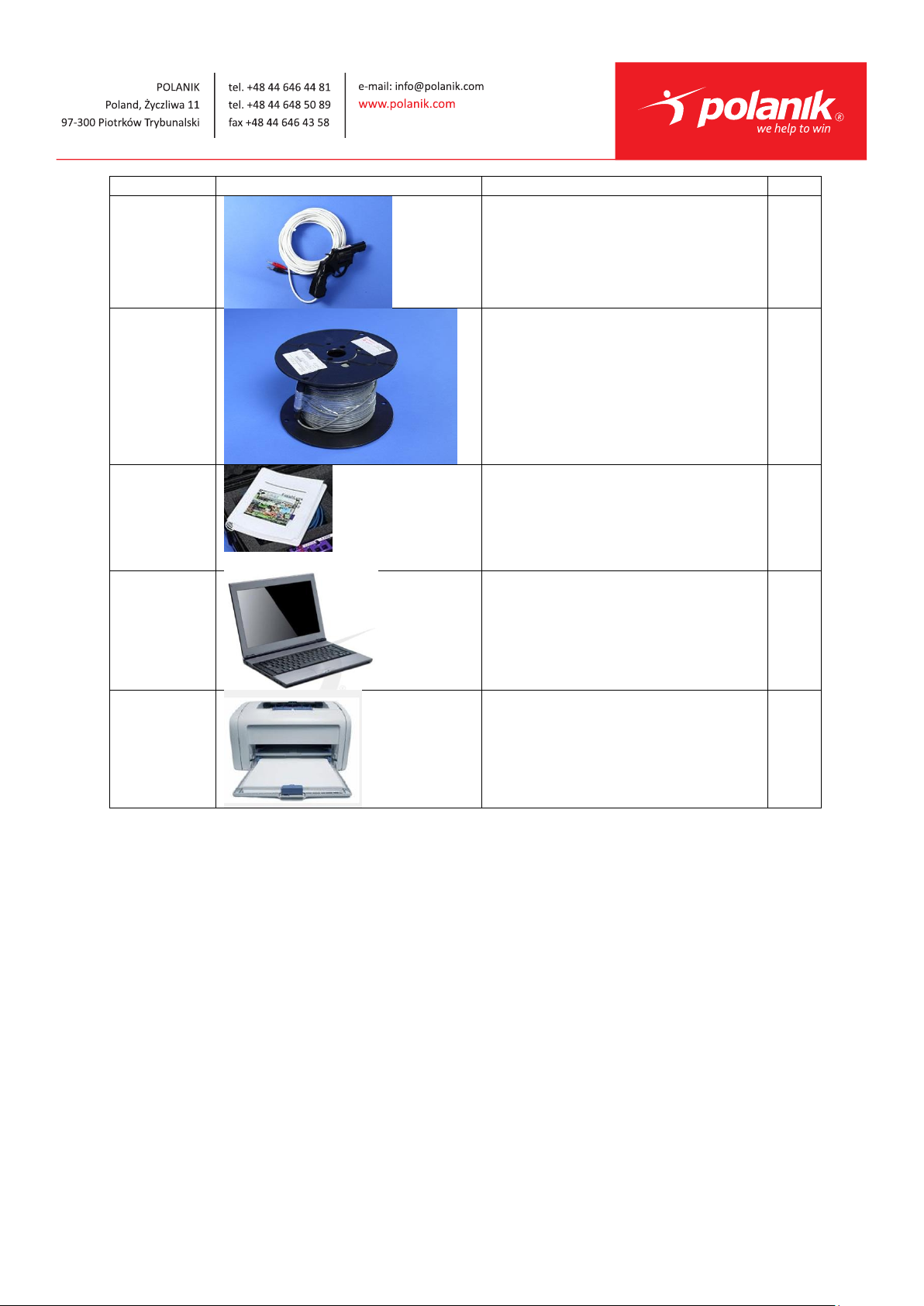
Step 4: Set up the camera and tripod
Setup the tripod in line with the finish line, preferably on the infield
and approximately 10 feet back. Note: Minimum recommended
camera distance from track is 8 feet (at this distance you may not be
able to see the feet of the athlete in Lane 1 –being able to see the
feet is not a requirement for accurate timing on the Torso of the
athlete). If you need to be closer than this you may have to use the
optional 6mm lens.
1. Extend the tripod legs so the geared head is approximately 7 ft
high.
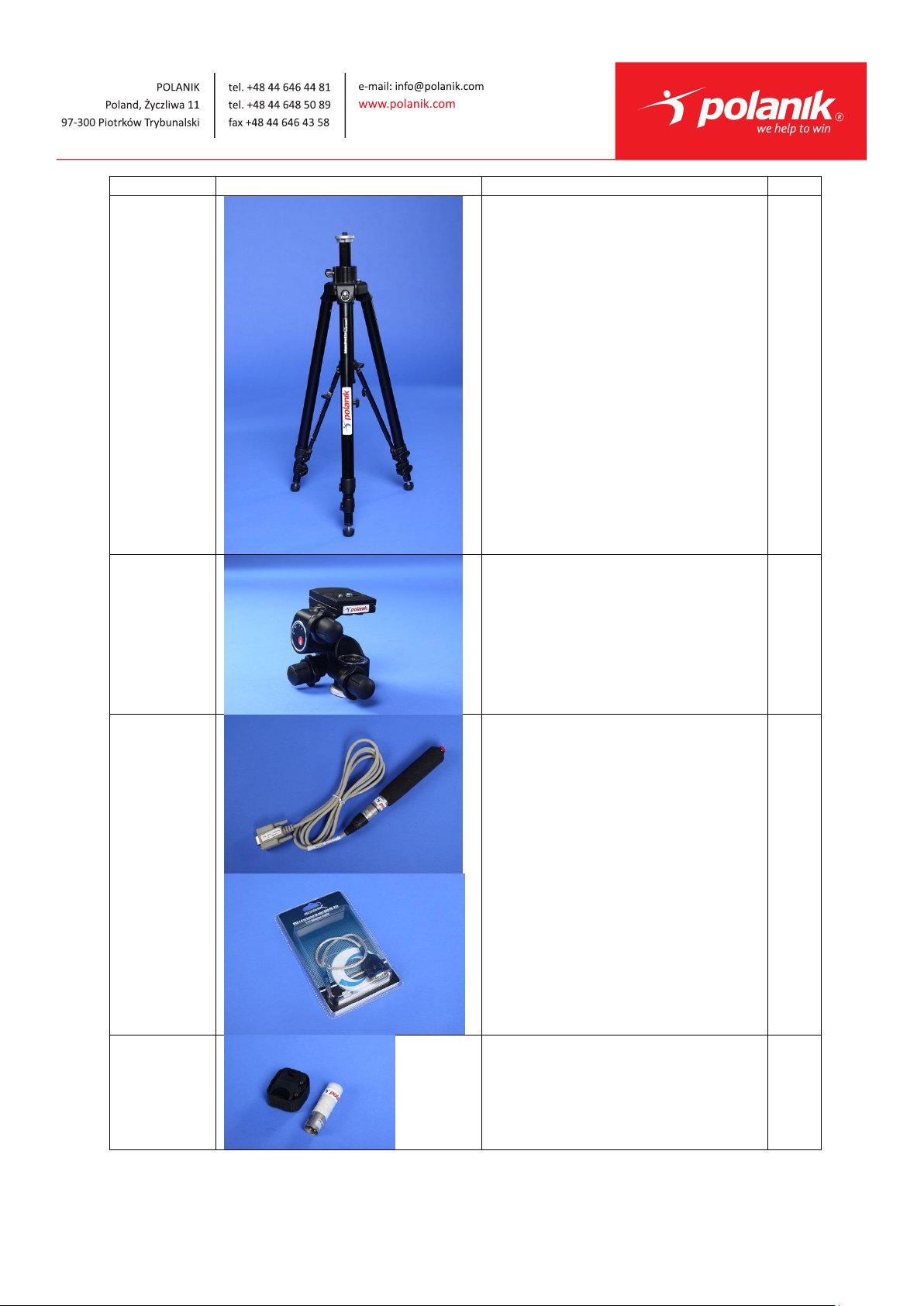
2. On the near side of the finish line, hold a plumb bob so that it is
suspended directly above the middle of the finish line. This is
the plumb line, shown as a in the image below.
3. Tie string to the screw on the top of the tripod head. Have your
assistant take the other end of the string to the far side of the
finish line and hold the string taught. This is the sight line,
shown as b in the image below.
4. Move the tripod to the left or right until the plumb line and
sight line touch at position C in the image below. The tripod is
now in the plane of the finish line.

Technical specification and instruction manual ZFFC 7 / 13
Step 5: Attach the camera to the tripod
1. If using the optional remote positioner, secure it to the camera
bottom by turning the black handled thumbscrew. Make sure
the FinishLynx label faces in the same direction as the camera
lens will face.
Note: Cables omitted for clarity and actual lens may vary from model shown
2. Connect the cable that comes with the remote positioner to the
port on the positioner and the port on the back of the camera
labeled Remote.
3. Connect the cable on the remote lens to the remaining serial
port on the remote positioner.

Technical specification and instruction manual ZFFC 8 / 13
4. Secure the geared head to the top of the tripod.
5. Note how the mounting plate is attached to the top of the
geared head. Then, pull back on the lever at the top of the
geared head to release the mounting plate.
6. Tighten the mounting plate to the bottom of the remote
positioner by turning the screw with a flathead screwdriver.
Make sure the Lens marking on the bottom of the plate is
facing the front of the remote positioner (where the Lynx label
is affixed).
7. Attach the camera with the remote positioner and mounting
plate to the tripod by clicking the mounting plate into place on
the geared head.
8. With the camera lens lined up with and facing the finish line,
make minor adjustments to the tripod legs so both bubbles on
the tripod are centered.
9. Turn the black knob on the geared head that controls the tilt of
the camera so that it is at about a 30 degree angle to the
ground.
Step 6: Connect the cables
Note: Alternate configurations shown below.

Technical specification and instruction manual ZFFC 9 / 13
Connection Box
Sensor
USB
Cat 5 Ethernet
DB 15 Cable
XLR
Capture
Button
PoE
Injector Cat 5 Ethernet
AC AC
EtherLynx Vision
Camera
AC
EtherLynx Vision
Primary Camera
Connection Box Sensor
DB 15 Cable
XLR
Capture
Button
Cat 5 Ethernet
IdentiLynx
Camera
Cat 5 Ethernet
AC
PoE
Switch
USB Button Splitter
EtherLynx Vision
Reverse Camera
Cat 5 Ethernet
Cat 5 Ethernet
1. Connect the female end of connection box cable to the port on
the back of the camera labeled Connection Box and the male
end to the left side of the connection box.
2. Connect an Ethernet cable between the back of the camera
labeled POE 10/100/1000 to the port labelled Out on the
Power over Ethernet injector.
3. Connect an Ethernet cable to the network connection on your
computer and the other end to a port labelled In on the Power
over Ethernet injector.
4. Connect the male end of the start sensor cable to the
connection box where it says Start. Attach the start sensor to

Technical specification and instruction manual ZFFC 10 / 13
the other end of the cable and keep the start sensor close by.
5. Turn on the camera by pressing and holding the black power
button on the back.
Step 7: Align the EtherLynx camera
Note: The EtherLynx Vision camera can be aligned using either 1-D
mode or 2-D EasyAlign mode. We recommend using EasyAlign. If you
are using an older model EtherLynx camera, however, it must be
aligned using classic 1-D mode.
NOTE If running a wireless Ethernet card on your computer, we
recommend that you disable it while the camera is booting.
Start FinishLynx. Wait while the green status bar in the lower right
corner of the screen completes its cycle.
Align Vision Camera in EasyAlign 2-D Video Mode
1. Activate EasyAlign by clicking on the 2D align Icon in the
top left hand corner of the FinishLynx Hardware Control
screen.
FinishLynx Quick Start Guide –for Vision cameras Page 4
The icon turns green and the 2-D video viewer appears
within the software. The 2-D viewer makes it easy to see how
your camera is aligned on the finish. The goal is to align the
green vertical line with the painted finish line and near its
front edge.
2. Adjust Remote Lens/Positioner Controls - Adjust the remote
lens/position controls on the right of the FinishLynx hardware
control screen.
Center Remote Camera Positioner
Click to center the camera automatically using the

Technical specification and instruction manual ZFFC 11 / 13
remote positioner.
Remote Camera Tilt, Pan & Swivel
Use the remote Tilt, Pan, and Swivel buttons to adjust the
orientation of the camera on the finish. You want to
ensure that the green vertical line is perfectly aligned on
the white finish line and that all lanes are visible in the
viewer.
Tilt
Pan
Swivel
Have your assistant run through the finish line and watch where
he/she appears on the computer monitor. The goal is for the
runner’s torso to be fully visible in both the inside and outside lanes.
Once the camera' position is correct, you can then optimize the
remote lens settings.
Remote Iris (adjusts amount of light in lens)
Open or Close the remote iris to bring the ACM value as close to 1 as
you can by clicking and holding the remote Iris buttons.
Remote Focus (adjusts near/far image focus)
Click and hold the and buttons on the keypad on the
right of the FinishLynx screen until the image becomes crisp. Start by
focusing on the far lane and adjust until all lanes are in focus. Ensure
that athletes in all lanes (near and far) are in focus.
Note: If you are having a hard time getting crisp focus, try opening
your lens iris and allowing the AGC to drop closer to zero.
3. Once the camera appears to be aligned, Click, the green
alignment icon to close 2D alignment and then click on the
red 1-D alignment icon . You will know when your camera
is aligned on the finish line because the 1-D image will be
primarily white. See image below for proper 1-D alignment.
4. If you followed the steps closely in 2-D align, the camera
should already be aligned in 1-D mode as well. The 1-D image
should look similar to the following screen capture:

Technical specification and instruction manual ZFFC 12 / 13
Step 8: Adjust FinishLynx camera settings
1. Click Camera Settings Icon to open the Camera Settings
dialog.
2. Click to select the Setup tab:
a. Name: enter a name to identify the camera(s)
b. Image Orientation: select the correct orientation for
finish (infield would be Left orientation)
c. Identify By: select Lane for track competition
d. Lanes: enter the number of lanes on the track; the
remaining should be left as default.
3. Click to select the Parameters tab
a. Rate: type a value in the field between 800-1000 for
sprints (400m and under) or type 600-800 for distance
events. Change this value when moving between sprints
and distance races, or else the competitors in your
FinishLynx image appear distorted.
Note: Image distortion does not affect timing accuracy.
b. Frame Height: will vary by camera models, 640 is
recommended for most track competitions;
c. Gain Method: set to AGC for outdoor light and set up. Set
Brightness to 70. Use Manual when needed.
4. Click to select the Inputs tab:
a. Start Sensor: is defaulted to Closed for the wired gun
start. If using the Radiolynx then set Start Sensor to None
to turn off the wired start (they are independent of each
other.

Technical specification and instruction manual ZFFC 13 / 13
5. Click to select the Capture tab:
a. Capture Method: select Manual if using the Capture
Button or Automatic if using ACM plug-in (both methods
can be active at the same time by selecting both).
6. Click OK to close the Camera Settings and it is advised to
restart the FinishLynx software.
7. Set White Balance
a. Open a new event in FinishLynx by clicking in the
top left corner of the screen.
b. Capture a small amount of image containing a white
object, such as a person wearing a white t-shirt.
c. Right-click and draw a box around a small amount of
the white image. You may need to zoom in to the
image to do this.
d. Click Image from the Menu bar and select Set white
balance.
Table of contents