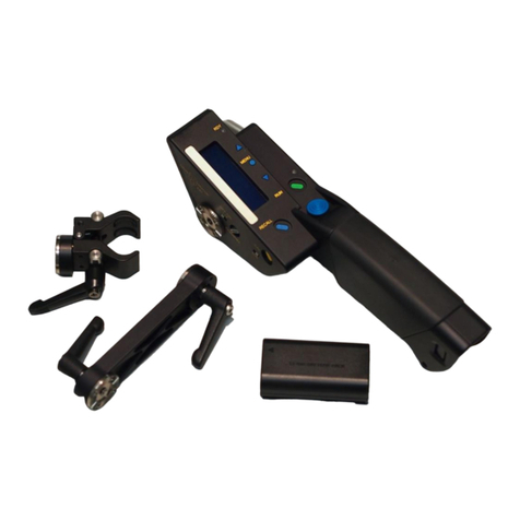
cmotion cvolutionLCS User manual

All content © 2017, cmotion GmbH. All specications subject to change without notice. http://www.cmotion.eu
V 1.10 | January, 9th 2018
Software Release Package: 2018_01
cvolutionLCS
User Guide

All content © 2017, cmotion GmbH. All specications subject to change without notice. http://www.cmotion.eu
Imprint & Disclaimer
cmotion GmbH
Wiedner Hauptstraße 135/B3
1050 Wien
Fbnr.: FN220240H – HG Wien
UID-Nr.: ATU 54026806
http://www.cmotion.eu
+43 1 7891096
Technical specications are
subject to change without notice!

All content © 2017, cmotion GmbH. All specications subject to change without notice. http://www.cmotion.eu
Table of Contents
1. Component Overview ......................................................... 3
1.1. camin 3M ............................................................................................. 3
1.2. Connectors and Controls on the camin 3M...............................................5
1.2.1. Technical Specications camin 3M ..........................................................................6
1.3. camin 8M/8M-TC 3D, Panoramic and Virtual Reality...................... 7
1.3.1. camin 8M ..................................................................................................................7
1.3.2. camin 8M-TC............................................................................................................8
1.3.3. Technical Specications camin 8M/8M-TC .............................................................9
1.3.4. Connectors and Controls on the camin 8M/8M-TC...............................................10
1.3.5. LED Status camin 8M/8M-TC ................................................................................11
1.4. cvolution camin wireless systems .................................................. 12
1.5. cvolution hand unit........................................................................... 13
1.5.1. Connectors and Buttons on the cvolution hand unit ............................................14
1.5.2. LED Status cvolution hand unit.............................................................................16
1.5.3. Technical Specications cvolution hand unit ........................................................17
1.6. cvolution basic knob ........................................................................ 18
1.7. cvolution advanced knob................................................................. 18
1.8. cvolution slider ....................................................................................................19
1.8.1. LEDs and Buttons of the slider...............................................................................19
1.9. cvolution zoom ....................................................................................................20
1.9.1. Connectors, Buttons and Display of the cvolution zoom.................................................. 21
1.9.2. Technical Specications cvolution zoom ..............................................................................21
1.10. cvolution knob solo .............................................................................................22
1.10.1.Connectors, Buttons and LEDs of the cvolution knob solo ..............................................23
1.10.2. Technical Specications cvolution knob solo .......................................................................23
1.11. cforce................................................................................................. 24
1.12. cforce mini......................................................................................... 25
2. cvolution system Accessories............................................ 26
2.1. Battery ............................................................................................... 26
2.2. Battery Charger ................................................................................ 26
2.3. cvolution CBUS splitter ...................................................................... 26
2.4. cvolution handle ..................................................................................................27
2.5. cstrap................................................................................................. 27
2.6. clamp II .............................................................................................. 27
2.7. cfastener............................................................................................ 28
2.8. cfast-czoom ...................................................................................... 28
2.9. cfast-vlock......................................................................................... 28

All content © 2017, cmotion GmbH. All specications subject to change without notice. http://www.cmotion.eu
2.10. cfast-artemis..................................................................................... 29
2.11. Additional Fastening Tools............................................................... 29
2.12. Antenna.............................................................................................. 30
2.13. Marker Ring....................................................................................... 30
2.14. Pre-marked Marker Rings ............................................................... 30
2.15. Marker Strip ...................................................................................... 31
3. System Setup..................................................................... 32
3.1. camin 3M/8M ...................................................................................... 32
3.1.1. Attaching camin to the Camera................................................................................32
3.1.2. Attaching cfast-vlock .............................................................................................33
3.1.3. Releasing cfast-vlock .............................................................................................33
3.1.4. Mounting the Antenna .............................................................................................33
3.2. Powering the camin and Connecting Motors.................................. 34
3.2.1. Connecting Motors to the camin 3M/8M .................................................................34
3.2.2. Changing CLM-4 gears ...........................................................................................35
3.2.3. Mounting Motors to Camera Support Rods............................................................36
3.3. cvolution hand unit..............................................................................................37
3.3.1. Battery .....................................................................................................................37
3.3.2. Mounting the cstrap ................................................................................................38
3.3.3. Mounting and Removing knobs ..............................................................................39
3.3.4. Marker Rings ...........................................................................................................39
3.3.5. Mounting and Remvoing sliders ...........................................................................................39
3.3.6. Marker Strips ...........................................................................................................39
3.4. cvolution zoom and cvolution handle.................................................... 40
3.4.1. Attaching the zoom unit on the hand unit ............................................................................. 40
3.4.2. Attaching the zoom to the cvolution handle ..............................................................41
3.4.3. Using cvolution zoom on the hand unit in Cable Mode ..........................................41
3.4.4. Attach cvolution zoom and handle to the Pan Bar..................................................42
3.4.5. Using the cvolution pan-bar zoom ..........................................................................42
3.4.6. Using the cvolution steady zoom ............................................................................43
4. Basic System Operation ................................................... 44
4.1. hand unit Status Display..................................................................... 44
4.2. hand unit Menu.................................................................................... 45
4.2.1. RF Channel Selection..............................................................................................45
4.2.2. camin.......................................................................................................................45
4.2.3. hand unit..................................................................................................................46
4.3. System Power Up ............................................................................. 47
4.3.1. camin.......................................................................................................................47
4.3.2. hand unit ..................................................................................................................48
4.3.3. Controller Priority.....................................................................................................48

All content © 2017, cmotion GmbH. All specications subject to change without notice. http://www.cmotion.eu
4.4. Motor Calibration.............................................................................. 49
4.4.1. Single Motor Calibration..........................................................................................49
4.4.2. Multiple Motor Calibration.......................................................................................49
4.4.3. Calibration Menu .....................................................................................................50
4.5. Motor Settings .................................................................................. 51
4.5.1. Motor Direction........................................................................................................51
4.5.2. Motor Torque ...........................................................................................................51
4.5.3. Motor Control ..........................................................................................................52
4.6. Working with cforce mini or plus motors ....................................... 53
4.7. Camera Run ...................................................................................... 54
4.7.1. Camera Run Button.................................................................................................54
4.7.2. Camera Run Simulation Function............................................................................54
4.8. Setting Limits .................................................................................... 55
4.8.1. Setting Knob Limits .................................................................................................55
4.8.2. Setting Mechanical Knob Limits..............................................................................55
4.8.3. Setting Lens Limits..................................................................................................55
4.8.4. Setting Lens Limits in Combination with Knob Limits ............................................56
4.8.5. Setting slider Limits ................................................................................................56
4.9. Locking Controllers .......................................................................... 57
4.9.1. Locking the knob.....................................................................................................57
4.9.2. Locking the slider ...................................................................................................57
4.10. Adjust advanced knob Torque......................................................... 58
4.11. advanced knob Illumination .............................................................. 58
4.12. Assigning Controllers....................................................................... 59
4.13. zoom Functions .................................................................................. 60
4.13.1. zoom Menu...............................................................................................................60
4.13.2.Zooming ..................................................................................................................62
4.13.3.Zoom Speed............................................................................................................62
4.13.4. zoom Buttons ...........................................................................................................62
4.13.5.Setting Zoom Limits ................................................................................................64
4.13.6.Changing Zoom Motor Direction.............................................................................64
4.14. Using the knob solo..........................................................................................65
4.14.1.Assigning Scales .....................................................................................................65
4.14.2.Setting Direction ......................................................................................................65
4.14.3.Calibration ...............................................................................................................65
4.14.4.Lens Limits ..............................................................................................................65
4.14.5.Knob Limits .............................................................................................................65
4.14.6.Advanced knob solo Illumination ............................................................................65
4.15. Stealth Mode ..................................................................................... 66
4.16. Creating/Editingalensleusingthecvolutionhandunit .......... 67
4.16.1.Focus scale .............................................................................................................68

All content © 2017, cmotion GmbH. All specications subject to change without notice. http://www.cmotion.eu
4.16.2.Iris scale...................................................................................................................68
4.16.3.T-stop ......................................................................................................................69
4.16.4.Zoom scale..............................................................................................................70
4.17. Working with Pre-Marked Marker Rings........................................ 70
4.18. Working with Lens Data ................................................................... 71
4.18.1. Loading a lens le from the cvolution hand unit......................................................73
4.18.2.Using lens data saved internally on a camin 3M ....................................................73
4.18.3.Loading a Lens when using a camin 8M ................................................................74
4.18.4.Unload Lens ............................................................................................................74
4.18.5.Invert Focus/Iris/Zoom ............................................................................................74
4.18.6.Delete Lens..............................................................................................................75
4.18.7.Create lens ..............................................................................................................75
4.18.8.Edit Lens..................................................................................................................75
4.19. Workingwitharangender ............................................................ 76
4.19.1.Autofocus ................................................................................................................76
4.19.2.Laser pointer............................................................................................................76
4.20. Software Version............................................................................... 78
5. Working with ARRI ALEXA Cameras............................... 79
5.1. Working with an ALEXA Plus ........................................................... 79
5.1.1. Connecting the hand unit and the camera.............................................................79
5.1.2. Motor Assignment ...................................................................................................79
5.1.3. Motor Calibration.....................................................................................................80
5.1.4. Features Not Available with ARRI ALEXA Plus........................................................81
5.2. Working with an ALEXA Mini ........................................................... 82
5.2.1. Assigning cforce mini / cforce plus Motors.............................................................82
5.2.2. Motor Calibration.....................................................................................................83
6. 3D System Operation........................................................ 84
6.1. Working With a Lens Pair................................................................. 84
6.1.1. Assigning Controllers for a Lens Pair ......................................................................84
6.1.2. Assigning Motors for a Lens Pair ............................................................................84
6.1.3. Synchronizing Scales ..............................................................................................86
6.2. Save/Load User Settings ................................................................. 89
6.3. cvolution System Setup for Mirror Rigs ......................................... 90
6.3.1. camin Setup .............................................................................................................90
6.3.2. stereographer hand unit Setup .................................................................................90
6.3.3. Setting the Zero Point..............................................................................................91
6.3.4. Blocking Negative Values ........................................................................................91
6.3.5. Setting Convergence/Interaxial Scaling ..................................................................92
6.3.6. Setting Plane Limits via Plane Scaling ....................................................................92
6.4. Automatic Convergence .................................................................. 93
6.5. Linking Scales................................................................................... 93

All content © 2017, cmotion GmbH. All specications subject to change without notice. http://www.cmotion.eu
6.6. Controlling H.I.T................................................................................ 94
6.7. Troubleshooting ................................................................................ 95
6.8. Screen Plane ..................................................................................... 95
7. Time Code and Meta Data................................................ 96
7.1. Setup ................................................................................................. 96
7.1.1. Connecting the Time Code Generator ....................................................................96
7.1.2. Preparing the USB Memory Stick ...........................................................................96
7.1.3. hand unit Setup......................................................................................................97
7.2. Time Code Operation ....................................................................... 98
8. Reference Section............................................................. 99
8.1. Using the cvolution hand unit Menu .................................................... 99
8.2. Connectors and Controls on the camin 3M...........................................104
8.2.1. Connectors and Controls, Top Side ......................................................................104
8.2.2. Connectors and Controls, Motor Side ..................................................................104
8.2.3. Connectors, CBUS Side........................................................................................104
8.3. Connectors and Controls on the camin 2M/4M/8M and 8M-TC 105
8.3.1. Connectors and Controls, Motor Side ..................................................................105
8.3.2. Connectors, CBUS Side........................................................................................105
8.3.3. LED Status camin 2M/4M/8M...............................................................................106
8.4. LEDs, Connectors and Buttons on the cvolution hand unit................107
8.4.1. Buttons ..................................................................................................................107
8.4.2. Connectors............................................................................................................107
8.5. LED Status cvolution hand unit.....................................................................109
9. Troubleshooting............................................................... 110
10. Version History ................................................................ 111

All content © 2017, cmotion GmbH. All specications subject to change without notice. http://www.cmotion.eu 1/112
Before Use
Dear Customer, we would like to take this opportunity to thank you for purchasing the cvolution
Lens & Camera Control System. Please read these operating instructions carefully and keep
them handy for future reference.
Information for Your Safety
■Danger of operational error!
■Danger of injury!
■Damage to equipment possible!
General Safety Precautions
■In order to ensure optimal performance, please read the instructions!
■ Do not put your ngers near the motors while motors are moving!
■Make sure all components (camin, lens motors, etc.) are securely mounted!
■Remove batteries from components before transport or storage!
■Repairs should only be made only by authorized service centers!
■Use only original cmotion replacement parts!
■In the case of wet weather, routine safety precautions for handling electrical
equipment in wet weather should be taken!
■Do not remove any screws that are secured with paint!
■Do not remove any warranty seals!
Important
■If you have questions, or you need to order parts, please note the components‘
model and serial number.
■For support requests, also supply the installed rmware number of all system
components.
■WARNING: cmotion can only guarantee operation if original cmotion products are
used.

All content © 2017, cmotion GmbH. All specications subject to change without notice. http://www.cmotion.eu 2/112
Using this Guide
This manual is split in three parts. The rst introduces you to the cvolution lens control system,
explaining components and concepts. The second takes you step by step through the setup
of the system. The third part guides you through operation and menu options. The table of
contents provides a reference guide to specic sections of this user guide for quick information.
Note: Notes indicate important information related to the respective
sections of this user’s guide.
Warning: Warnings indicate important safety information. Ignoring
these could lead to equipment damage or injury.
All cmotion components are written in italics throughout this manual.
Cables
When a cable is referred to in this user’s manual, it is identied by its connectors. E.g. Fi 16p,
Le 4p. Connectors are manufactured by W. W. Fisher, Lemo or Hirose and are referred to as
Fi, Le and Hi respectively. The cable identication begins with the connector that is attached
to the cmotion product (camin) followed by the connector which is attached to non-cmotion
product or cmotion accessory. Each connector also takes reference from the number of pins it
has. E.g. Fi 16p, Hi 12p means that the cmotion connector is a 16pin Fischer and the other end
is a 12pin Hirose.
Cables may also be referred to by their commonly used names e.g. CBUS (Le 8p, Le 8p).
Occasionally, cable connectors are referred to as ‘m’ or ‘f’ to identify whether the connector is
male or female. For a full overview of cables, please download the cmotion cable guide from
www.cmotion.eu.
Necessary Tools
A 4mm Allen key may be required to complete steps laid out in the manual.
Frequently Used Terms
To Power Cycle: Turn your unit o and on again

All content © 2017, cmotion GmbH. All specications subject to change without notice. http://www.cmotion.eu 3/112
1. Component Overview
This section of the User Guide deals with the description of the components and their respective
functions, LEDs and buttons.
1.1. camin 3M
The new cvolution camin 3M is a compact, lightweight and low prole interface for focus, iris
and zoom control. Motors can be controlled wirelessly or by cable using modular cvolution
hand units. Popular broadcast controllers can also be used through a new analog interface.
The discrete CAL button triggers auto motor calibration while the EXT connector provides an
interface for wireless run/stop for a wide range of cameras. The unique LBUS connector allows
for up to 3 daisy-chained cforce/cforce mini motors to be used independently or synchronized
for a totally exible 6 motor set up.

All content © 2017, cmotion GmbH. All specications subject to change without notice. http://www.cmotion.eu 4/112
The camin 3M is an advanced model driving up to six motors.
CBUS Side Motor Side

All content © 2017, cmotion GmbH. All specications subject to change without notice. http://www.cmotion.eu 5/112
1.2. Connectors and Controls
on the camin 3M
Connectors and Controls, Top Side
ON-Switch Turn camin on or o.
Note: The voltage boost on the camin 3M is activated via the hand unit menu.
Channel Dial Set the desired RF channel.
Channel 1-9 for Black RF.
Channels 0-7 for ARRI White RF.
Antenna port Connect the supplied antenna to this port. To achieve optimum wireless range
the antenna is required.
Connectors and Controls, Motor Side
LBUS port You can connect up to 3 cforce/cforce mini motors to the LBUS port in a daisy
chain fashion. Assign these motors to axis via the hand unit menu.
Motor ports The camin 3M oers three Fi or Le motor ports. The standard axis assignment
on these is as follows: M1 Focus, M2 Iris, M3 Zoom but can be changed via
the hand unit menu.
Connectors, CBUS Side
RS 9-35 V power connector with standard ARRI pinout.
ANA To control motors using traditional broadcast controllers. Optional CEN-1 /
CEN-2 cables required.
CBUS The CBUS port allows accessories like the cnder to connect to the camin. It is
also used for cable operation and software updates.
EXT Camera /3rd party interface. If your camera is capable of communicating with
the camin, it can be connected to the EXT port for camera control. You can
also connect two cameras to EXT via split cable.

All content © 2017, cmotion GmbH. All specications subject to change without notice. http://www.cmotion.eu 6/112
1.2.1. TechnicalSpecicationscamin 3M
General
■Wireless communication: 2.4Ghz RF*
■Temperature range: -20 °C to + 50 °C
■Power Supply Voltage: 9 - 35 V
■Height 105 mm (4 1/8 in)
■Width 64 mm (2 1/2 in)
■Depth 24 mm (1 in)
■Weight 245 g (8 3/4 oz)
*For information on the RF module refer to section 1.4 on page 12.

All content © 2017, cmotion GmbH. All specications subject to change without notice. http://www.cmotion.eu 7/112
1.3. camin 8M/8M-TC 3D,
Panoramic and Virtual Reality
1.3.1. camin 8M
The camin 8M is capable of driving up to 8 passive motors plus/or up to 3 active motors. Thus,
it is ideally suited for complex setups including 3D, panoramic and virtual reality.
CBUS Side Motor Side
v

All content © 2017, cmotion GmbH. All specications subject to change without notice. http://www.cmotion.eu 8/112
1.3.2. camin 8M-TC
The camin 8M-TC is the camin 8M’s big brother. In addition to the regular 8M features, 8M-TC
has a 5pin SMPTE TC input allowing it to record lens and rig meta data synchronised with time
code. This data can be recorded to a USB stick or output via the CBUS serial output.
CBUS Side Motor Side
v

All content © 2017, cmotion GmbH. All specications subject to change without notice. http://www.cmotion.eu 9/112
1.3.3. TechnicalSpecicationscamin 8M/8M-TC
General
■Wireless communication: 2.4Ghz RF
■Temperature range: -20 °C to + 50 °C
■Power Supply Voltage: 9 - 35 V
■Weight: 650 g (approx. 23 oz)
*For information on the RF module refer to section 1.4 on page 12.

All content © 2017, cmotion GmbH. All specications subject to change without notice. http://www.cmotion.eu 10/112
1.3.4. Connectors and Controls
on the camin 8M/8M-TC
Connectors and Controls, Motor Side
ON-Switch Turn camin on or o
In position I the motor voltage equals the input voltage.
In position II the motor voltage is boosted internally to 26V but draws a higher
current. If using position II, make sure your camera or power supply is capable
of providing sucient Amps.
Typical current requirements per motor connected are:
Supply voltage 24V 12V
ON=I 0.5A 0.5A
ON = II 0.6A 1.1A
Channel Dial Set the desired RF channel.
Channel 1-9 for Black RF
Channels 0-7 for ARRI White RF
Antenna port Connect the supplied antenna to this port. To achieve optimum wireless range
the antenna is required.
Motor ports Depending on your camin model there are up to 8 passive motor ports on this
side of the camin. Connectors are either Fi 12p or Le 7p connectors.
Connectors, CBUS Side
USB connector The USB port is used for import/export of User Settings and recording of meta
data (camin 8M-TC only)
RS-1 9-35 V power connector with standard ARRI pinout.
This is the primary power connector for camin 8M-TC
RS-2 9-35 V power connector with standard ARRI pinout.
This is the primary power connector for camin 4M and 8M
Note: When using more than 4 motors, it is highly recommended that you use
both RS jacks to power the camin.
CBUS ports The CBUS port allows accessories like the cnder to connect to the camin. It is
also used for cable operation and software updates.
Please note: Second CBUS port available on camin 8M-TC only. CBUS 2 is
also used for serial meta data output.
EXT-1, EXT-2 Camera and 3rd party interface. Up to two cameras can be controlled through
EXT-1 via a split cable.The camin can be powered through the EXT ports, pref-
erably EXT-2..
Motor ports On the camin 8M, motor ports 7 and 8 are found on this side of the camin.
TC SMPTE LTC Time Code In. Use this port to input time code from any time code
generator capable of putting out SMTPE TC (camera, TC slate etc).
Please note: TC port available on camin 8M-TC only.

All content © 2017, cmotion GmbH. All specications subject to change without notice. http://www.cmotion.eu 11/112
1.3.5. LED Status camin 8M/8M-TC
RF LED/ON LED
(Operation
Status)
RF LED ON LED camin Status Solution
O O camin o
check camin ON/OFF switch
check power supply voltage
(9 V minimum)
check for cable damage
O Flashing
Red/Green
camin ready, (cable
mode, channel selector
set at 0 or RF o)
no client logged on
turn on clients
Flashing
Red
Flashing
Red/Green
camin ready (wireless
mode), no client logged
on
turn on clients
O Green camin ready, client
logged on in cable mode
OK
Green Green
camin ready, client
logged on in wireless
mode
OK
Red Flashing
Red/Green
During Start-Up: camin
is booting up
Selected channel already
in use by another camin
Channel is currently be-
ing changed
Hardware fault
turn o camin and change
radio channel
If that does not work, please
contact cmotion.
Green
Flashing
Flashing
Red
Software incompatible
between camin and
clients
update all components
Red Flashing
Red
Low battery camin will
not work
change Power Supply
Motor LED
Flashing Red Motor Error
check motor cable
If no reason can be found,
please contact cmotion
Green Motor ready
Green/ Flashing Red
System is calibrating
motor cannot reach its
position
check if lens torque is too
high and lens damage
check lens calibration
O No motor connected check motor cable
check if camin is turned on
TC LED
O No time code input
check TC cable
check if TC generator is
powered on and set up
correctly
Green Time code signal present
and device in sync
Flashing Green
Time code running out of
sync (40 minutes warning
before sync is lost)
Reconnect TC generator and
re-sync within 40 minutes
Red, followed by Green Syncing with TC signal Do not disconnect the TC in
cable
Flashing Red, Red TC out of sync Re-sync with TC generator

All content © 2017, cmotion GmbH. All specications subject to change without notice. http://www.cmotion.eu 12/112
1.4. cvolution camin wireless systems
cvolution systems are available in 2 wireless versions. The rst, and “standard RF at time of
writing”, is ARRI White. This is identied with either a white dot or white disc on the antenna
module of each cvolution hand unit. A white antenna port is used to identify the white RF
module in all cvolution camin.
The white system oers integration into ARRI’s Wireless Lens Control System (WLCS) and is
fully compatible to the ALEXA Plus and other WLCS cameras.
■Selectable RF channels: 0-7
■Max Active users: 3
■camin software releases: 3.11.x
■The cdisplay II and the czoom II can only be used in cable mode.
The black system is the legacy cvolution system. Most important technical specs are:
■Selectable RF channels: 1-9
■Max Active users: 4
■Selectable RF power.
■camin software releases: 3.11.x
■The czoom II can only be used in cable mode.

All content © 2017, cmotion GmbH. All specications subject to change without notice. http://www.cmotion.eu 13/112
1.5. cvolution hand unit
The cvolution hand unit is the modular hand-held control unit of the cvolution Lens Control
System. The base unit can be expanded with several modules for controlling lens and/or
rig motors. The construction is light-weight and ergonomic with a user friendly and intuitive
interface.
cvolution hand unit (without slider and knob)
cvolution hand unit (with slider, knob, zoom and cdisplay II)
Table of contents
Other cmotion Control System manuals
Popular Control System manuals by other brands
mr. steam
mr. steam iGenie 104129 Installation and operation instructions
HySecurity
HySecurity HydraWedge SM50 installation instructions
Water Furnace
Water Furnace IntelliZone2 MasterStat Specification Catalog and Design Guide
Skytech
Skytech RCTS-MLT-IV Installation and operation instructions
Fly Sky
Fly Sky Paladin PL18 user manual
Ultra Max
Ultra Max UM-2100-762 Installation, operation and maintenance manual
