Fly Sky Paladin PL18 User manual

User ManualUser Manual
Copyright ©2022 Flysky Technology co., ltd
This product is only for 15 years
old or above.

Thank you for purchasing our products.
Read the manual carefully to ensure your personal safety as well as the safety of your
equipment.
If you encounter any problems during using, please refer to this manual rst. If the
problem is still not resolved, please contact the local dealer directly or contact the
customer service sta via the website below:
http://www.ysky-cn.com

Table of Contents
1. Safety ........................................................1
1.1 Safety Icons .......................................................................1
1.2 Safety Guide ......................................................................1
2. Battery Safety Instructions ......................2
3. Product Description .................................3
3.1 System Features ................................................................3
3.2 Transmitter Overview .......................................................4
3.2.1 Transmitter Antenna ...........................................................7
3.2.2 Stick/Knob/Switch/Button .................................................7
3.2.3 Status LED .............................................................................7
3.2.4 Stick mode ............................................................................8
3.2.5 Gimbal Adjustment ..............................................................8
3.2.6 Power Switches ...................................................................9
3.2.7 Charging Mode ....................................................................9
4. Pre-operation Setup ...............................10
4.1 Receiver and Servo Installation .....................................10
5. Operation Guidelines .............................11
5.1 Power On .........................................................................11
5.2 Binding ............................................................................11
5.3 Pre-operation Checks .....................................................12
5.4 Power O .........................................................................12
6. Main Interface .........................................13
6.1 Main Interface Overview .................................................13
6.1.1 Status Bar (Top) ..................................................................14
6.1.2 Quick Access .......................................................................14
6.2 Interface ...........................................................................15
6.2.1 Function Icons ....................................................................15
7. Basic Settings .........................................16
7.1 Display Servos ................................................................17
7.1.1 Display Servos ...................................................................17
7.1.2 Channel Test ......................................................................17
7.2 Model Select ....................................................................18
7.2.1 Searching for the receiver .................................................18
7.2.2 Copying a model ................................................................19
7.2.3 New model ..........................................................................19
7.2.4 Selecting a model ..............................................................19
7.2.5 Deleting a model ................................................................20
7.3 Model Setup ....................................................................20
Model type setup .........................................................................20
7.4 Reverse ...........................................................................22
7.5 Channel route .................................................................23
7.6 Subtrim ............................................................................23
7.7 Function Assignment ......................................................24
7.7.1 Assigning function items .................................................24
7.7.2 Control assign ....................................................................24
7.7.3 Function Trim Assignment ..............................................25
7.8 Trim ..................................................................................26
7.8.1 Setting TR1 trim ................................................................26
7.8.2 Setting VRA trim ................................................................27
7.9 Sensors ............................................................................28
7.9.1 Displaying Sensors ............................................................28
7.9.2 Sensors setup .....................................................................29
7.10 Timers ...........................................................................33
7.10.1 Timer 1/2 ...........................................................................33
7.10.2 Engine timer .....................................................................33
7.10.3 Model timer ......................................................................33
7.11 RF setting ......................................................................34
7.11.1 Transmit ............................................................................34
7.11.2 RF set to be on by default ...............................................34
7.11.3 RF Type ..............................................................................34
7.11.4 PPM setting .......................................................................35
7.11.5 RF rmware updating .....................................................35
7.11.6 RF version..........................................................................35
7.12 RX setting ......................................................................36
7.12.1 Bind setting .......................................................................36
7.12.2 Custom port protocol ......................................................36
7.12.3 Failsafe...............................................................................37
7.12.4 PWM frequency ................................................................38
7.12.5 Low signal voice alarm ...................................................39
7.12.6 Low voltage voice alarm .................................................39
7.12.7 BVD voltage calibration ..................................................40
7.12.8 Cong RX as a PWM converter .......................................40
7.12.9 i-BUS2 device display ......................................................41
7.12.10 Set i-BUS2 HUB as a PWM converter ..........................42
7.12.11 i-BUS2 PWM converter setting .....................................42
7.12.12 i-BUS2 GPS sensor setting ............................................43
7.12.13 i-BUS setting ...................................................................45
7.12.14 Signal strength output setting .....................................45
7.12.15 Midpoint oset ...............................................................46
7.12.16 Receiver Update .............................................................46
7.12.17 About Receiver ...............................................................46
7.13 Trainer mode ................................................................47
7.13.1 Student mode ..................................................................47
7.13.2 Trainer mode ....................................................................48
8. Airplane/Glider Exclusive Function
Setting .........................................................51
8.1 Display servos ................................................................52
8.2 Condition ........................................................................52
8.2.1 Editing ..................................................................................52
8.2.2 Creating/copying a condition ..........................................53
8.2.3 Deleting a condition ..........................................................53
8.2.4 Setting a condition to default condition ........................53
8.2.5 Changing the order of the conditions ............................53
8.3 Func. Rate(AFR) ..............................................................54
8.3.1 Setting Curve type .............................................................54
8.3.2 Setting Rate/EXP/Oset ....................................................54
8.4 DR setting ........................................................................55

8.5 Channels Oset ...............................................................55
8.6 Program Mixs ..................................................................56
8.6.1 Setting Master and Slave ..................................................56
8.6.2 Setting Mix delay ................................................................58
8.6.3 Setting Mix rate ...................................................................58
8.7 Servo speed ....................................................................58
8.7.1 Servo speed- Set by function ...........................................59
8.7.2 Servo speed- Set by channel ...........................................59
8.7.3Servo speed- Set by condition .........................................60
8.8 Throttle curve ..................................................................60
8.9 Throttle cut ......................................................................61
8.10 Idle up ............................................................................61
8.11 Throttle needle .............................................................62
8.12 Aileron ...........................................................................62
8.12.1 Aileron dierential ...........................................................63
8.12.2 Aileron elevator ................................................................63
8.12.3 Aileron camber ap .........................................................63
8.12.4 Aileron brake ap .............................................................64
8.12.5 Aileron to elevator ...........................................................64
8.12.6 Aileron to rudder ..............................................................64
8.13 Flap ................................................................................65
8.13.1 Flap setting .......................................................................65
8.13.2 Brake to Airfoil .................................................................66
8.13.3 Airfoil to Elevator ............................................................66
8.13.4 Airfoil to Elevator ...........................................................67
8.14 Airbrake .........................................................................67
8.14.1 Brake speed .....................................................................68
8.14.2 Brake rate .........................................................................68
8.15 Spoiler ...........................................................................68
8.16 Elevator ..........................................................................69
8.16.1 Elev. Linkage ....................................................................69
8.16.2 Elev. Aileron .....................................................................70
8.16.3 Elev. to Airfoil Flap ..........................................................70
8.16.4 Elev. to Brake Flap ..........................................................71
8.17 Rudder ...........................................................................71
8.17.1 Rudd. Linkage ..................................................................71
8.17.2 Rudd. to Aileron ..............................................................72
8.17.3 Rudd. to Aileron ..............................................................72
8.18 Buttery .........................................................................73
8.19 V tail ...............................................................................73
8.20 Logic switches ...............................................................74
9. Helicopter Exclusive Function Setting ...75
9.1 Display servos ................................................................75
9.2 Condition ........................................................................75
9.3 Func. Rate (AFR) .............................................................75
9.4 DR setup ..........................................................................75
9.5 Channel oset ................................................................75
9.6 Pro. Mixes ........................................................................75
9.7 Servo speed ....................................................................75
9.8 Throttle curve .................................................................76
9.9 Pitch curve ......................................................................76
9.10 Throttle cut ....................................................................76
9.11 Idle up ............................................................................76
9.12 Throttle hold ............................................................76
9.13 Throttle needle .............................................................77
9.14 Swashplate ................................................................77
9.15 Thro mixed ................................................................77
9.16 Swashplate ring ...........................................................77
9.17 Hover adjust ..............................................................78
9.18 Gyroscope .................................................................79
9.19 Governor ....................................................................79
9.20 Logic switches ...............................................................79
10. Multicopter Exclusive Function Setting
.....................................................................80
10.1 Display servos ..............................................................80
10.2 Condition ......................................................................80
10.3 Func. Rate (AFR) ...........................................................80
10.4 DR setup........................................................................80
10.5 Channel oset ..............................................................80
10.6 Pro. Mixes ......................................................................80
10.7 Servo speed ..................................................................80
10.8 Throttle curve ...............................................................81
10.9 Throttle hold .................................................................81
10.10 Attitude ........................................................................81
11. Car Exclusive Function Setting .............82
11.1 Display servos ..............................................................82
11.2 Condition ......................................................................82
11.3 Func. Rate (AFR) ...........................................................82
11.4 DR setup........................................................................82
11.5 Channel oset ..............................................................82
11.6 Pro. Mixes ......................................................................82
11.7 Servo speed ..................................................................82
11.8 Throttle curve ...............................................................83
11.9 ABS ................................................................................83
11.10 Track mixing ...............................................................85
11.11 Logic switches ............................................................85
12. Boat Exclusive Function Setting ..........86
12.1 Display servos ..............................................................86
12.2 Condition ......................................................................86
12.3 Func. Rate (AFR) ...........................................................86
12.4 DR setup........................................................................86
12.5 Channel oset ..............................................................86
12.6 Pro. Mixes ......................................................................86
12.7 Servo speed ..................................................................86
12.8 Throttle curve ...............................................................86
12.9 Logic switches ..............................................................86
13. Robot Exclusive Function Setting ........87
13.1 Display servos ..............................................................87
13.2 Condition ......................................................................87

13.3 Func. Rate (AFR) ..........................................................87
13.4 DR setup.......................................................................87
13.5 Channel oset .............................................................87
13.6 Pro. Mixes .....................................................................87
13.7 Servo speed .................................................................87
13.8 Throttle curve ..............................................................87
13.9 Track mixing ................................................................88
13.10 Logic switches ...........................................................88
14. System setting .....................................89
14.1 General function setting ..............................................89
14.1.1 Language setting ......................................................89
14.1.2 Units ...........................................................................89
14.1.3 Sound ........................................................................90
14.1.4 Vibration ....................................................................90
14.1.5 Auto search for receiver ...........................................90
14.1.6 Factory reset .............................................................91
14.1.7 TX rmware updating ..............................................91
14.1.8 About Paladin PL18 ..................................................91
14.2 Display setting ..............................................................92
14.2.1 Backlight timeout ....................................................92
14.2.2 Backlight brightness ................................................92
14.2.3 Standby timeout ......................................................92
14.2.4 Autoshut down .........................................................93
14.3 Qucik access setting ....................................................93
14.4 Switches setup .............................................................94
14.4 Stick calibration ...........................................................94
14.5 Range test .....................................................................94
14.6 Hlep center ...................................................................95
15. Custom menu setting .........................96
16. Same common operation items setting
....................................................................97
16.1 Switch assignment ......................................................97
16.1.1 Normal ON/OFF switch setting .....................................97
16.1.2 Position-switch setting ..................................................97
16.1.3 continuous switch setting .............................................98
16.1.4 Logic switch setting ........................................................99
16.2 Linear setting ...............................................................99
18. Product Specication ........................101
19. Package Contents ..............................102
20. Certications .....................................103
20.1 DoC .............................................................................103
20.2 CE Warning .................................................................103
20.3 Appendix 1 FCC Statement .......................................103
20.4 Environmentally friendly disposal ...........................104
1
• Improper use of this product may lead to serious injury or death to the user and others.
To ensure the safety of yourself and others read and follow the instructions set out in
the user manual.
• To avoid damage to the model, make sure that the product and model are installed
correctly before use.
• Always power o the receiver before the transmitter. Powering o the receiver before
the transmitter could lead to loss of control.
• Before use make sure that all the servos and motors are moving in the correct direction.
• Make sure to remain within range to prevent loss of control.
• Do not y at night or in bad weather like rain or thunderstorm. It can cause erratic
operation or loss of control.
• Do not use the product when the visibility is limited.
• Do not use the product on rainy or snowy days. Should any type of moisture (water or
snow) enter any component of the system, erratic operation and loss of control may
occur.
• Interference could cause loss of control. To ensure the safety of you and others, do not
operate in the following places:
• Near any site where other radio control activity may occur.
• Near high voltage power lines or communication broadcasting antennas.
• Near water with passenger boats nearby.
• Near high voltage wires or communication/broadcast antennas.
• Do not use this product if you are tired, uncomfortable or when using substances that
may impair your ability to use the product safely.
• The 2.4GHz frequency band requires line of sight from the transmitter to receiver at all
times. Avoid large obstacles that could block or interfere with the signal.
• In order to ensure good signal quality, do not hold the transmitters antenna during use.
• Parts of the model, such as motors or ESC’s may remain hot for a period of time after
use and can cause severe burns.
Prohibited Mandatory
1. Safety
1.1 Safety Icons
Pay attention to the following icons and their meanings. Failure to follow these guidelines can result in equipment
damage or personal injury.
1.2 Safety Guide
CAUTION • Not following these instructions may lead to major injuries.
WARNING • Not following these instructions may lead to minor injuries.
DANGER • Not following these instructions may lead to serious injuries or death.
2
2. Battery Safety Instructions
DangerDanger
This products battery is rechargeable
and non-removable. Do not remove
the battery from the product.
Do not charge the battery in direct
sunlight, in a hot car or near anything
hot such as cookers etc.
Do not charge without ventilation.
Do not use near ammable liquids or
gasses.
Charge Transmitter Battery before
use.
If there is not enough quantity of electricity
during the ight, it will lead to a airplane crash.
Do not solder, repair, modify or
disassemble the battery.
Do not Tap the charger or battery
during charging.
May cause burns
Keep the battery away from any
heat source if it is leaking or causing
strange smells.
May catch re or explode.
WARNINGWARNING
Do not charge batteries that show
any evidence of damage, aging,
leakage or exposure to liquids.
Do not expose the battery to liquids.
Do not use a damp battery. Keep your hands
try during use and do not leave batteries in areas
with lots of moisture.
Do not Tap the positive and negative
terminals of the battery together.
Do not throw the battery into a re.
Do not throw or impact the battery.
May cause re or an explosion.
Put some tape on the battery's
terminals before recycling.
If the short circuit causes re, heat, rupture, etc.
Do not store the battery in dusty or
humid environments.
Remove dust from the power connector before
plugging in.
Do not charger the battery when
exposed to extreme heat or cold.
May lead to a drop in battery performance.
To ensure maximum performance always charge
the battery within the temperature range of
10℃~30℃.

3
3. Product Description
PL18 is an 18-channel air transmitter with 2.4GHz AFHDS 3 (third-generation automatic frequency hopping digital
system). And there is a variety of built-in models that you can set as your desired. It adapts xed-wing aircraft,
helicopters, gliders, multicopters, robots, boats or cars.
3.1 System Features
AFHDS 3 (third-generation automatic frequency hopping digital system) is a newly developed digital wireless system
with independent intellectual property rights by FLYSKY. It is compatible with one-way and two-way real-time data
packet transmission and transparent data stream transmission.In other words, this system has advantages of both
AFHDS 2A and WS2A wireless system. It equips with a brand-new 2.4G chip, stable and reliable connection, good
real-time performance, and supports various congurations. Bring you the optimal conguration for multi-scenario
application performance.
Compatible with
Unidirectional/
Bidirectional
Real-time Data
Transmission
The system supports one-way and two-way connections. When the transmitter is working
in one-way transmission way, the receiver can receive data from the transmitter. When the
transmitter is working in two-way transmission way. The receiver can receive data from
the transmitter and the transmitter can also receive data from the receiver, as well as the
information cross from the temperature and speed sensor modules.
Data Transparent
Transmission
The independent data transparent transmission module is built into RF system, which can
realize data transmission via transmitter and transparent transmission. It can be used for data
transmission of ight control.
Intelligent RF
conguration
To set the parameters which aect RF transmission distance, speed and anti-interference,
such as numbers of channels, resolution, bandwidth and receiver sensitivity. The system
can be set according to dierent application requirements to obtain the most suitable
performance.
Multi-channel
Frequency Hopping
This systems bandwidth ranges from 2.402GHz to 2.480GHz. Set intelligent RF congurations
accordding to your required, it can avoid or reduce the interference from other transmitters
with the same frequency via dierent congurations, dierent time of powering on the
transmitter, various patterns to the hopping frequency and various using frequency spots.
Unique ID
Recognition System
Each transmitter and receiver has it's own unique ID. Once the transmitter and receiver
have been bound, they will save the each other's ID and only connect with each other. When
the syetem is working,if the IDs are matched with each other, then the connection will be
connect, otherwise, there is no connection between transmitter and receiver. This unique
ID recognition syetem resists the interference so as to make the system stabler and more
reliable.
Low Power
Consumption
It is built using highly sensitive, low power consumption components. And it works in the
way of interval data transmission to improve transmitting ecient eectively and extend the
working time of the battery distinctly, while it consumes as little as one tenth the power of a
standard FM system.

4
3.2 Transmitter Overview
[1] Antenna [11] TR5 Trim [21] TR2 Trim
[2] LED Screen [12] Speaker [22] SWC Button
[3] SWF Position Switch [13] TR7 Trim [23] Transmittter Status Indicator
[4] SWE Position Switch [14] VRA Knob [24] Neck Strap Hook
[5] SWB Position Switch [15] VRB Knob [25] Right Stick
[6] VRD Knob [16] Power Switch [26] TR4 Trim
[7] TR1 Trim [17] SWD Position Switch [27] TR6 Trim
[8] SWA Button [18] SWH Position Switch [28] TR8 Trim
[9] Left Stick [19] SWG Position Switch [29] VRC Knob
[10] TR3 Trim [20] VRE Knob [30] Power Switch
Front View
[3]
[4]
[2]
[1]
[5]
[6]
[7]
[8]
[9]
[10]
[12]
[11]
[13]
[14]
[15]
[16]
[18]
[19]
[17]
[20]
[21]
[22]
[23]
[24]
[25]
[26]
[27]
[28]
[29]
[30]

5
Front View- Reset button
Reset button
The reset button is on the lower part of the transmitter as shown above. You need to tear apart the grip to nd
it. To press it by using a long thin tool, such as a smaller screwdriver.
In case of the transmitter can not be powered o by pressing the two Power Switches, please reset the
transmitter with the Reset button.
CAUTION • After resetting, the settings which set before resetting may be invalid.

6
Back View
[31] Bluetooth Module interface [38] Carrying Handle
[32] FRM301 Status Indicator [39] Press to release FRM301
[33] FRM301 Button [40] FRM301 RF Module
[34] Gimble Tension Adjustment [41] Gimbal Tension Adjustment
[35] Grip [42] Grip
[36] Micro USB interface [43] Screw holes for xing RF Module adapter
[37] Trainer Jack [44] Wireless Charging Area
[31]
[32]
[33]
[35]
[36]
[37]
[38]
[40]
[42]
[39]
[44]
[34] [41]
[43]

7
3.2.1 Transmitter Antenna
PL18 transmitter has two built-in antennas. When the transmitter starts to work, the antennas automatically
operate, without additional operations.
CAUTION • To ensure a good signal do not cover or block the antenna.
3.2.2 Stick/Knob/Switch/Button
The PL18 has 2 sticks (Left stick and right stick), 6 switches (SWB, SWD, SWE, SWF, SWG and SWH) , 5 knobs (VRA to
VRE) and 2 buttons (SWA and SWC), and 8 trim buttons ( TR1 toTR8).
Sticks: Output dierent value when it is in dierent position, they can output continuous signal. And they can be
used as function controls, as well as switches to turn on/o the function.
Knobs: The knobs can implement the same function as sticks. Part of them can be used as trim controls.
Switches: There are two-position switches and three-position switches. Dierent value is corresponding to dierent
position. They can be used as function controls, as well as switches to turn on/o the function.
Buttons: The buttons can implement the same function as switches.
Trim buttons: Output dierent value when toggling up/down. They can be used as function controls, refer to 7.8
Trim for detailed.
3.2.3 Status LED
The status LED is used to indicate the power supply state of the transmitter and its working state. The LED lights up
in three states: gradual light, ashing, and solid on.
• The LED is o, indicating that the transmitter is powered o.
• When the screen is o , and the LED is in gradual light state:
1. The LED colour changes alternatively among cyan, magenta, and yellow. It indicates that the RF is enabled
and the receiver is not connected or bound in one-way.
2. The LED colour is yellow, indicating that the RF is disabled and the receiver is not connected.
3. The LED colour changes alternatively among red, green and blue. It indicates that the RF is enabled and the
receiver is connected.
• When the screen is on, and the LED is solid on:
1. The LED colour is blue, indicating that the RF is enabled and the receiver is not connected or bound in one-
way.
2. The LED colour is yellow, indicating that the RF is disabled and the receiver is not connected.
3. The LED colour is green, indicating that the RF is enabled and the receiver is connected successfully.
• The LED is ashing in red, indicating that there is an alarm.
• The LED is ashing fast in green, indicating that the binding is in progress.
• The LED is cyan: The transmitter is powered on until it starts successfully.
Note: When the binding and an alarm are generated at the same time, the binding takes priority. That is, the LED will
be ashing fast in green.
Note: This function is available for 1.0.65 or above.

8
Function Settings:
By adjusting the screws on the back of the transmitter, gimbal stick can be either self-return or non self-return, as
well as changing stick tension/friction.
Available options:
CAUTION
• When the counterclockwise adjustment is made, the entire range of movement of the
screw is about 6 circles(the tightest to the loosest). Be cautious not to adjust it too far
or the screw will fall out.
Take left gimbal as example:
Non Self-return to Self-return:
Self-return to Non self-return:
①.⑤ To change the gimbal sticks self-return or non self-
return. ②.⑥ To change vertical tension strength of
the gimbal sticks.
③.⑦ To change horizental tension strength of the gimbal
sticks. ④.⑧ To change the vertical friction strength
of the gimbal sticks
1. Use a Phillips screwdriver to adjust the screw ①counterclockwise until the gimbal reaches its
median position.
2. Adjust screw ④counterclockwise to adjust the frictional strength.
3. If you need to adjust the strength of the return, adjust screw ②to change the strength of return to
the median position, and to strengthen the strength clockwise, otherwise it's to reduce.
1. Use a Phillips screwdriver to adjust the screw ① clockwise so that the gimbal is no longer at its
median position.
2. Adjust the screw ④clockwise to strengthen or reduce the frictional strength.
3. If you need to adjust the strength of the return, adjust screw ②change the strength of return to the
median position, and to strengthen the strength clockwise, otherwise it's to reduce.
3.2.4 Stick mode
This system supports four stick modes. As for aircraft models, from channel 1 to channel 4, by default, these four
channels are assigned to aileron, elevator, throttle, and rudder. There are four preset modes of the sticks in order
to meet the dierent requirements. You can select suitable mode among Mode1, Mode2, Mode3 and Mode4. The
green icon indicates the currently selected mode, and the default mode is Mode 2. You can select suitable mode as
your desired. Then you need to adjust the gimbals as needed to match the mode. Follow the steps below.
Function Settings:
Enter the Model Setup interface via Home1 > Basic > Model,
then tap the function box next to Stick to enter the stick mode.
Select the mode as your desired. Then click to return.
3.2.5 Gimbal Adjustment
Be used to adjust the states of sel-return and resilience strength of the 5D multiplex stick.
Back View of gimbal Viwe of Stick's Swing
①
②
③
④ ⑤
⑥
⑦
⑧
Note: It is also can be set in updating wizard interface after the transmitter
rmware is updated. The factory preset mode for the stick can be set in this
interface. Only transmitter rmware version 1.0.55 or above has this function.

9
3.2.6 Power Switches
To prevent false triggering, there are two switches on the lower part of the transmitter. Turn on or turn o the
transmitter when both switches are pressed at the same time.
3.2.7 Charging Mode
PL18 can be charged in two ways:
1. Plug the micro USB cable into the Micro USB interface of the transmitter for charging.
2. Use the wireless charging dock to charge it.
Notes:
1. Charge it within the safe range (4h@5V*2A/). Overcharging may lead to battery damage.
2. To prolong the service life of the battery, properly discharge if you want to store it for a long time (that is, not fully charged). In
addition, you need to charge it regularly to prevent damage due to not-operation for long term.
3. The transmitter will shut down automatically along with a voice reminder if the voltage is lower than 3.4V.
4. When the battery of the transmitter is in over discharge state and the transmitter is powered o, and at this time if the transmitter is
to be charged, it will be in a slow charging mode.
CAUTION • Please use the micro USB cable shipped with this transmitter. Improper use may cause
damage to the battery and aect its service life.

10
Make sure that the receiver is mounted in an appropriate location within the model, to ensure a stable signal,
maximum range and to mitigate external interference, follow these guidelines:
Pay attention to the following when installing the receiver:
1. 1. Make sure the receiver is not installed near ESCs or other sources of electrical noise. Make sure the receiver is not installed near ESCs or other sources of electrical noise.
2. 2. Keep the receivers antenna away from conductive materials such as carbon or metal. To ensure normal Keep the receivers antenna away from conductive materials such as carbon or metal. To ensure normal
function make sure there is a gap of at least 1cm between the antenna and the conductive material.function make sure there is a gap of at least 1cm between the antenna and the conductive material.
4. Pre-operation Setup
Follow the instructions and guidelines in this chapter before use.
4.1 Receiver and Servo Installation
CAUTION • To prevent damage do not power on the receiver during installation.

11
1. Check to make sure the receiver is installed correctly and that the receiver is powered o.
2. Press and hold both Power Switches until the screen lights up.
3. Power on the receiver.
5. Operation Guidelines
Follow these guidelines to use the transmitter and the receiver.
5.1 Power On
Follow the steps below to power on:
CAUTION • The system is now active, be cautious to not cause damage or personal injury.
CAUTION
• If SWA/SWB/SWC/SWD/SWE/SWF/SWG/SWH switches are not at their high positions
and the throttle stick is not at its low position when the transmitter is powered on.
A prompt will appear to remind you to put these switches and throttle stick to their
proper positions. It is recommended to follow the reminder to put them to their proper
positions. The transmitter will launch. If you click Go to launch the transmitter without
putting them to their proper positions, this may lead to danger.
5.2 Binding
The transmitter and the receiver have been pre-bound at the factory. If you need to rebind or bind a new receiver
follow the steps below. The Flysky AFHDS 3 receivers are consisted by classic version receivers and enhanced version
receivers. The bind method is slightly dierent between these two versions.
Note: Flysky AFHDS 3 classic version receiver models: FTr10/FGr4/FGr4s/FGr4p/FTr4/FTr16S. Other Flysky AFHDS 3 receivers are enhanced
version receivers.
Note: When you choose one-way
communication, the receiver does not send the
data to the transimitter, the indicator ashes
slowly after the receiver receives the bind
information. You need to manually put the
transmitter to exit the bind mode. When the LED
of the receiver is solid on, it indicates that the
binding is completed.
WARNING
• Power o the servo while the transmitter and the receiver is binding. Otherwise it may
lead to danger.
• After the binding process is completed, power o the receiver, then power on the
receiver and check to make sure that the transmitter and the receiver have bound
successfully.
To enter the Bind setting interface via Home1 > Basic function > RX setting.
Two way: To set the transmitter and the
receiver to connect in one-way or two-way. If
the appears, indicating that the transmitter
and the receiver are connected in two-way.
Click Bind to put the transmitter into bind
mode. After that a menu will pop up a menu
which is showing the binding process.
To adapt Flysky AFHDS3
classic version receivers. After
clicking Bind, a menu prompt
of adaptive receivers will be
popped up.
The binding interface of classic receiver:
Note: This function is available for version 1.0.55 or above.

12
1. Inspect the entire system to make sure that everything is working as expected.
2. Perform a range test as described in the 16.6 Range Test section of the user manual.
DANGER • Do not use the model if there are any abnormal behaviors during the test.
DANGER • Do not exceed the maximum rated range during use.
CAUTION • Interference from other transmitting devices may reduce signal quality.
5.3 Pre-operation Checks
Always perform the following steps before each operating:
1. Power o the receiver.
2. Press and hold both Power Switches on the transmitter until the screen powers o.
5.4 Power O
Follow these steps to power o the system:
DANGER • To avoid any risk of loosing control of the model, always power o the receiver before
powering o the transmitter.
Note: After powering o the transmitter, please wait for 3 seconds before turning it on again.
Since it takes time to store data after the transmitter screen goes o, you need to wait for 5S before powering it on
again. The transmitter will not reboot immediately in the restart after the screen is turned o.
The binding interface of enhanced receiver:
Provides 18 channels with moderate
communication distance.
Provides 12 channels with super
anti-interference and moderate
communication distance.
Note: Routine 18ch, Lora 12ch and Fast
8ch can only be bound with enhanced
receivers.
Provides 8 channels, fast
communication within short distance.
To set the starting channel of the
primary receiver.
To set the starting channel of the
secondary receiver.
To increase/decrease a value. Increases a
value by tapping + and decreases a value
by tapping -.
To bind the transmitter with the secondary
receiver. Click it to put the transmitter into
bind mode.
To bind the transmitter with the
primary receiver. Click it to put the
transmitter into bind mode.
To set double receivers or not. If there is a
tick, indicating that the double receivers
are set.
Function Settings:
1. Power on the transmitter, enter the bind setting interface via Home
1> Basic > RX setting.
2. Tap Bind setting and enter the binding setting interface. Then set
some items, such as selecting suitable RF System, choosing two way
or not, or setting the starting channel. Afterwards, click Bind to put
the transmitter into bind mode.
3. Put the receiver into bind mode (Refer to the manual of the receiver
for details.)
4. The LED of the receiver stops ashing and is solid on, indicating that
the binding process is completed.
5. Check to make sure the transmitter and receiver are working
correctly, repeat steps 1 to 3 (binding process) if any problems arise.

13
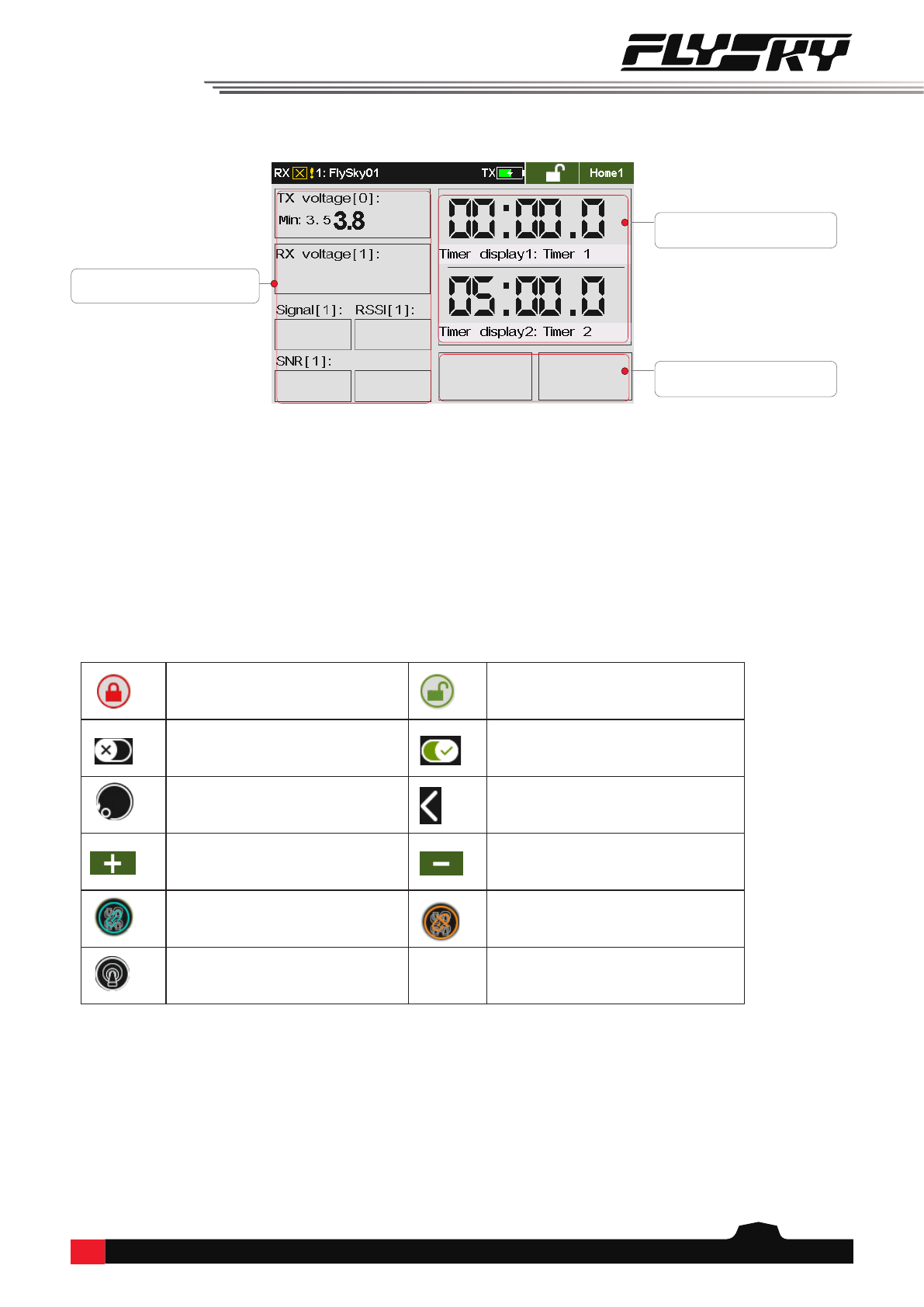
6.1 Main Interface Overview
The main interface displays information related to the model such as sensor information and function status.
6. Main Interface
This is an introduction about the transmitter's main interface.
Model Name Transmitter Power Status
Lock/Unlock Icon
Status Column: Some function icons are
showed if the function is activated in this
area, such as Conditions( ), Vibration
( ) and Sound( ). Dierent function
icons will be shown in this area in various
conditions, the details are as follows:
• Airplane: Airbrake( ), Buttery( ),
Throttle cut ( )and Idle up ( )
• Gliders: Airbrake and Buttery
• Helicopters: Throttle cut, Idle up and
Throttle hold ( )
• Multicopters: Throttle hold ( )
• Cars: ABS ( )
Preview of all trim value
Home1:
Home2:
The voltage of transmitter and receiver
The area of entering the Basic function screen
The area of entering the System
function screen
The icon of entering the Home1
The icon of entering the Timer1
The icon of entering the Timer2
The icon of entering the Sensor 8
Setup
The icon of entering the Sensor
7 Setup
The icon of entering the
Sensor 6 Setup
The icon of entering the
Sensor 5 Setup
The icon of entering the
Sensor 4 Setup
The icon of entering the
Sensor 3 Setup
The icon of entering the
Sensor 2 Setup
The icon of entering the
Sensor 1 Setup
The icon of entering the
Bind setting interface
The icon of entering the
Select model interface
The icon of entering the
Custom menu interface
The area of entering the Model
function screen
RX/RF Status
Note: Adjust the menu layout, it is available for version 1.0.65 or above.

14
6.1.2 Quick Access
Tap this area to quickly access the
System function interface.
Tap this area to quickly access the
Basic function interface.
Tap this area to quickly access the
Model function interface.
Tap this area to quickly access
the Trim interface.
Tap this area to quickly access
the Custon Menu interface.
Tap this area to quickly access
the Select model interface.
Tap this area to quickly access
the Bind setting interface.
Note: There would be no
information in this area, if the RF
type is PPM or CRSF.Tap this area to quickly access the
Sensor interface.
Signal strength. This icon won't be displayed if a receiver connects the transmitter in one-way mode.
The RF moudle is ennable, but the receiver is not connected. The icon won't be displayed when the
transmitter has bound with the receiver in one-way mode.)
To tap this icon along with a pop-up interface, then tap Yes to go into the Bind setting interface.
The RF moudle is disabled.
The transmitter has bound with the receiver in one-way mode.
Home icon. Tap this icon to enter the Home2.
Unlock icon. Tap this icon to lock the screen.
Lock icon. Tap and hold this icon for 1 sencond to
unlock the screen.
6.1.1 Status Bar (Top)
Currently selected model number and name.
Charging
Low Voltage
Battery is full.
Home1:
15
Indicates that the screen/function is
locked
Indicates that the screen/function is
unlocked
Function Disabled Function Active
Restore to the default Go Back Icon
To increase the value To decrease the value
For all conditions. For the current condition.
Assign Switches
Tap this area to quickly access
the Sensor 1~6 interface.
Tap this area to quickly access
the Timer interface.
Tap this area to quickly access
the Sensor 7~8 interface.
6.2 Interface
This section is a quick introduction about the icons of the interface.
6.2.1 Function Icons
Home2:
Table of contents
Other Fly Sky Control System manuals

Fly Sky
Fly Sky FS-GT2 User manual

Fly Sky
Fly Sky HRZ00020 User manual

Fly Sky
Fly Sky FS-ST8 User manual

Fly Sky
Fly Sky FS-ST8B User manual

Fly Sky
Fly Sky FS-i6 Installation manual

Fly Sky
Fly Sky FS-MG4 User manual

Fly Sky
Fly Sky FS-BS6 User manual

Fly Sky
Fly Sky FS-G4P User manual

Fly Sky
Fly Sky FS-T4B User manual

Fly Sky
Fly Sky FMS-G7 User manual

Fly Sky
Fly Sky FS-G4P-BS User manual

Fly Sky
Fly Sky FS-MG41 User manual

Fly Sky
Fly Sky FS-iA6B Quick start guide

Fly Sky
Fly Sky FS-HW-G4P User manual

Fly Sky
Fly Sky FS-G7P User manual

Fly Sky
Fly Sky FS-GT2F User manual

Fly Sky
Fly Sky FS-IT4S User manual

Fly Sky
Fly Sky FS-GT2 User manual

Fly Sky
Fly Sky Paladin PL18 EV User manual

Fly Sky
Fly Sky FS-i6 User manual


