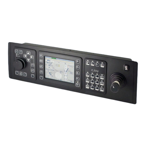
Kongsberg AIS 200 User manual

Manual part no: A102-04
Kongsberg AIS 200
User's Manual
Issued: 2005-05-09

Blank page

III
Notice
•All rights reserved. Reproduction of any of this manual in any form whatsoever without
prior written permission from Kongsberg Seatex AS is forbidden.
•The contents of this manual is subject to change without notice.
•All efforts have been made to ensure the accuracy of the contents of this manual.
However, should any errors be detected, Kongsberg Seatex AS would greatly appreciate
being informed of them.
Copyright 2005 by Kongsberg Seatex AS. All rights reserved.
Kongsberg Seatex AS
Pirsenteret, N-7462 Trondheim, Norway
Telephone: +47 73 54 55 00
Facsimile: +47 73 51 50 20
Duty phone: +47 73 50 21 11
www.kongsberg.com

IV
Blank page

V
Revision log
Document ID Rev. Date Reason for revision Approved
(sign)
Man_user_ais200_r0 0 2004-12-09 First version. KKr
Man_user_ais200_r1 1 2005-02-24 LAN extension included. Static Data
and Voyage Related menus updated.
PCB
Man_user_ais200_r2 2 2005-05-09 Minor updates after reviews.
Appendix E - Inland Waterway
functionality included.
PCB

VI
Blank page

VII
Table of contents
1. INTRODUCTION............................................................................................................. 1
1.1 About this manual...................................................................................................... 1
1.2 References..................................................................................................................2
1.3 Definitions, abbreviations and acronyms .................................................................. 2
1.3.1 Abbreviations and acronyms ......................................................................... 2
2. SYSTEM OVERVIEW..................................................................................................... 5
2.1 General....................................................................................................................... 5
2.1.1 Coverage ........................................................................................................ 5
2.1.2 AIS information content ................................................................................ 6
2.1.2.1 Static data........................................................................................... 6
2.1.2.2 Voyage related data............................................................................ 6
2.1.2.3 Dynamic data ..................................................................................... 6
2.1.2.4 Safety-related messages ..................................................................... 6
2.1.2.5 Data reporting and transmission rates................................................ 6
2.2 System components ................................................................................................... 7
3. USER INTERFACE.......................................................................................................... 9
3.1 AIS 200 user interface ............................................................................................... 9
3.1.1 Display ........................................................................................................... 9
3.1.2 Keypad ........................................................................................................... 9
3.1.3 LED indicators............................................................................................... 9
3.2 Buttons..................................................................................................................... 10
3.3 Using display and keypad........................................................................................ 11
3.3.1 Manoeuvring and selecting.......................................................................... 11
3.3.2 Dialogue boxes ............................................................................................ 12
3.3.3 Editing.......................................................................................................... 13
3.3.4 Information .................................................................................................. 13
3.4 AIS 200 display pages and submenus ..................................................................... 14
3.4.1 Ship list view ............................................................................................... 15
3.4.2 Main menu ................................................................................................... 16
3.4.3 Alarms and LR............................................................................................. 16
3.4.4 Dynamic data ............................................................................................... 17
3.4.5 Settings......................................................................................................... 17
3.4.6 SMS.............................................................................................................. 19
3.4.7 Downperiods................................................................................................ 21
3.4.8 Channel Management .................................................................................. 21
3.4.9 System.......................................................................................................... 23
3.4.10 Diagnostics................................................................................................... 24
3.4.11 Pin code protection ...................................................................................... 25
3.5 Optional MKD unit.................................................................................................. 26
3.5.1 Display ......................................................................................................... 26

VIII
3.5.2 Rotating knob............................................................................................... 26
3.5.3 Display page buttons.................................................................................... 26
3.5.4 Input buttons ................................................................................................ 26
3.6 Optional MKD - display pages and submenus ........................................................ 27
3.6.1 Displaying submenus................................................................................... 28
3.6.2 Entering Data ............................................................................................... 28
3.6.3 View page .................................................................................................... 29
3.6.4 Menu page.................................................................................................... 30
3.6.5 SMS page..................................................................................................... 31
3.6.6 Alarm page................................................................................................... 31
4. SOFTWARE SETUP PROCEDURE............................................................................ 33
4.1 General..................................................................................................................... 33
4.2 Security settings....................................................................................................... 33
4.3 Entering static data .................................................................................................. 34
4.4 Network settings ...................................................................................................... 34
4.5 Configuring external serial ports ............................................................................. 35
4.6 VHF data link .......................................................................................................... 35
4.7 Configuring radio channels...................................................................................... 35
4.7.1 Viewing a region's settings .......................................................................... 35
4.7.2 Adding a region ........................................................................................... 36
4.7.3 Edit current region ....................................................................................... 37
5. OPERATION................................................................................................................... 39
5.1 General..................................................................................................................... 39
5.2 Turning the AIS 200 system ON ............................................................................. 40
5.3 Restarting the AIS 200 system ................................................................................ 40
5.4 Adjusting brightness and contrast............................................................................ 40
5.4.1 AIS 200 display settings .............................................................................. 40
5.5 Changing parameters during operation.................................................................... 41
5.5.1 Setting the Navigational Status.................................................................... 41
5.5.2 Entering Voyage Data.................................................................................. 41
5.6 Turning the VHF transmitter OFF........................................................................... 41
5.7 Using the AIS 200 message system......................................................................... 41
5.7.1 Using SMS in AIS 200 ................................................................................ 41
5.7.2 New SMS received ...................................................................................... 42
5.7.3 The Inbox..................................................................................................... 42
5.7.4 Write Message ............................................................................................. 42
5.7.5 The Outbox .................................................................................................. 43
5.7.6 Viewing and editing predefined messages................................................... 43
5.7.7 How to write a predefined message............................................................. 43
5.8 The alarm system..................................................................................................... 43
5.8.1 AIS 200 alarms ............................................................................................ 43
5.8.2 Displaying and acknowledging alarms ........................................................ 44

IX
5.9 Long-Range messages (option) ............................................................................... 44
5.9.1 AIS 200 long-range...................................................................................... 44
5.9.2 Deleting a long-range request ...................................................................... 44
6. APPENDIX A - OPERATING PROCEDURE OPTIONAL MKD ........................... 45
6.1 Optional MKD display settings ............................................................................... 45
6.2 Setting the navigational status ................................................................................. 45
6.3 Entering voyage data ............................................................................................... 46
6.4 Turning the VHF transmitter OFF........................................................................... 47
6.5 Using SMS in AIS 200 - optional MKD ................................................................. 48
6.5.1 Receiving and reading an SMS message ..................................................... 48
6.5.2 Writing and sending SMS messages............................................................ 49
6.5.2.1 Writing general text messages and safety related messages ............ 49
6.5.2.2 Writing broadcast messages............................................................. 50
6.5.2.3 Writing predefined messages ........................................................... 51
6.5.2.4 Sending a predefined message ......................................................... 52
6.6 The Outbox .............................................................................................................. 52
6.6.1 Removing messages..................................................................................... 53
6.7 Optional MKD alarms ............................................................................................. 54
6.8 Displaying and acknowledging alarms.................................................................... 54
6.9 Optional MKD long-range....................................................................................... 55
6.9.1 Resolving a long-range request.................................................................... 55
6.9.2 Deleting a long-range request ...................................................................... 56
6.10 Restarting the AIS 200 system using optional MKD .............................................. 56
7. APPENDIX B - SOFTWARE SETUP USING OPTIONAL MKD............................ 57
7.1 Security settings optional MKD .............................................................................. 57
7.1.1 Setting the security codes ............................................................................ 57
7.1.2 Changing the security levels ........................................................................ 58
7.2 Entering static data optional MKD.......................................................................... 59
7.3 Network settings optional MKD.............................................................................. 60
7.4 Configuration external serial ports optional MKD.................................................. 61
7.5 Port settings and MAC address optional MKD ....................................................... 62
7.6 Answer mode optional MKD................................................................................... 62
7.7 Configuring radio channels optional MKD ............................................................. 63
7.7.1 Adding a region ........................................................................................... 64
7.7.2 Editing current region .................................................................................. 65
7.7.3 Viewing a region’s settings.......................................................................... 65
8. APPENDIX C - TYPE APPROVAL CERTIFICATE ................................................ 67
9. APPENDIX D - DECLARATION OF CONFORMITY ............................................. 71
10. APPENDIX E - INLAND WATERWAY FUNCTIONALITY................................... 73
10.1 Setup file.................................................................................................................. 73
10.2 Dynamic data ........................................................................................................... 73

X
10.3 Inland data ............................................................................................................... 73
10.4 Inland Waterway Area data ..................................................................................... 74
10.5 Inland Waterway Static Ship data............................................................................ 74
10.6 Inland Waterway Voyage Ship data ........................................................................ 74
10.7 Ship data parameters................................................................................................ 75

Kongsberg AIS 200 User's Manual, rev. 2 Introduction
1
1. INTRODUCTION
1.1 About this manual
This manual contains the information necessary to operate the AIS 200 Automatic
Identification System.
In this manual, references to buttons on the control unit are written in boldface, and in a
different text style (e.g. VIEW button, SHIFT button, ENTER button).
This manual is organised into the following chapters:
Chapter 1 Introduction - A brief overview of this manual with references and
abbreviations.
Chapter 2 System overview - An overview of the AIS 200 system and its components.
Chapter 3 User interface - An overview of the AIS 200 user interface, display pages and
menus and the Minimum Keyboard and Display (MKD) unit.
Chapter 4 Software setup procedure - Initial software parameters that have to be entered
before the system is ready to use.
Chapter 5 Operation - Main operating procedures for using the AIS 200 system.
Appendix A - Operating procedures optional MKD - Describes the operating procedure when
using the optional MKD.
Appendix B - Software setup using optional MKD - Initial software parameters that have to
be entered before the system is ready to use when using the optional MKD.
Appendix C - Type approval certificate - Copy of type approval certificate included.
Appendix D - Declaration of conformity - Copy of Declaration of Conformity included.
Appendix E - Inland Waterway functionality.
In this manual the following notations are used:
Caution! Is used to make the user aware of procedures and operational practice
which, if not followed, may result in degraded performance or damage to the
equipment.
Note! A note text has this format and is used to draw the user's attention to special
features or behaviour of the equipment.
FCC part 15 statement
This equipment has been tested and found to comply with the limits for a Class A digital
device, pursuant to Part 15 of the FCC Rules. These limits are designed to provide reasonable
protection against harmful interference when the equipment is operated in a marine and/or

Kongsberg AIS 200 User's Manual, rev. 2 Introduction
2
commercial environment. This equipment generates, uses and can radiate radio frequency
energy and, if not installed and used in accordance with the instruction manual, may cause
harmful interference to radio communications. The equipment is not inteded for operation in a
residential area. Operation in such an area is likely to cause harmful interference in which
case the user will be required to correct the interference at his own expense.
Additional information to the user
Changes or modifications not expressly approved by Kongsberg Seatex AS will void the
user's authority to operate the equipment.
1.2 References
[1] Kongsberg AIS 200 Installation Manual, 2005
1.3 Definitions, abbreviations and acronyms
1.3.1 Abbreviations and acronyms
AIS Universal Ship-borne Automatic Identification System
AIS 1 161.975 MHz (87B – 2087)
AIS 2 162.025 MHz (88B – 2088)
ALR Alarm
ATN Aids to Navigation
BS Base Station
COG Course Over Ground
DSC Digital Selective Calling
ETA Estimated Time of Arrival
GPS Global Positioning System
HDG Heading
ICMP Internet Control Message Protocol
IMO International Maritime Organisation
IP Internet Protocol
IWW Inland WaterWay
LAN Local Area Network
LED Light Emitting Diode

Kongsberg AIS 200 User's Manual, rev. 2 Introduction
3
LR Long Range
MKD Minimum Keyboard Display
MMSI Maritime Mobile Service Identity
MSG Message
N/A Not Applicable
PI Presentation Interface
PWR Power
ROT Rate of Turn
RTCM Radio Technical Commission of Maritime Service
RX Receive
SMS Short Message Service
SOG Speed Over Ground
SWR Standing Wave Ratio
TX Transmit
UTC Universal Co-ordinated Time
UTP Unshielded Twisted Pair
VDL VHF Data Link
VDO VHF Data Link Own Vessel Message
VHF Very High Frequency
VTS Vessel Traffic Service

Kongsberg AIS 200 User's Manual, rev. 2 Introduction
4
Blank page

Kongsberg AIS 200 User's Manual, rev. 2 System overview
5
2. SYSTEM OVERVIEW
2.1 General
The Kongsberg Seatex AIS 200 Automatic Identification System (AIS) uses VHF
communication to transmit and receive AIS data. An AIS system operates primarily on two
dedicated VHF channels, AIS 1 – 161.975 MHz and AIS 2 – 162.025 MHz. Where these
channels are not available regionally, the AIS can be set to alternate designated channels.
The system broadcasts the vessel's position, speed and course over ground as well as static
and voyage related information. Short safety related text messages can be sent between
vessels or broadcast from shore based AIS stations or Aids to Navigation like buoys and
lighthouses. The on-board installed system is designed to operate automatically and as a
stand-alone unit. In addition to transmission of AIS data, the system can continuously receive
position information from other vessels or shore based stations.
2.1.1 Coverage
The radio coverage range is similar to other VHF applications and is dependent on the height
of the antennas. The propagation differs from that of a radar, due to the longer wavelength, so
it is possible to "see" around bends and behind islands if the landmasses are not too high. A
typical value to be expected between vessels is 20 - 30 nautical miles.
GPS
SATELLITES
BASE
STATIONS
OPERATOR
STATION

Kongsberg AIS 200 User's Manual, rev. 2 System overview
6
2.1.2 AIS information content
AIS information is exchanged automatically between vessels, vessels and shore based stations
and vessels and Aids to Navigation like buoys and lighthouses. The information transmitted
by the AIS system is grouped into four categories:
2.1.2.1 Static data
•MMSI (Maritime Mobile Service Identity) number
•Call sign and name
•IMO number
•Length and beam
•Location of position fixing antennas on the ship
2.1.2.2 Voyage related data
•Ship's draught
•Hazardous cargo type
•Destination and ETA (at Master's discretion)
•Type of ship
2.1.2.3 Dynamic data
•Position with accuracy indication and integrity status
•Time in UTC
•COG (Course over ground)
•SOG (Speed over ground)
•Heading
•Navigational status
•Rate of turn
2.1.2.4 Safety-related messages
•Reading and writing short safety related messages
2.1.2.5 Data reporting and transmission rates
AIS data as stated above are autonomously sent at different update rates. The reporting rates
are dependent on the ship's navigational mode. Dynamic information is dependent on speed
and course alteration while static and voyage related data are transmitted every 6 minutes or
on request. Thus fast ferries will report their navigational data at a higher update rate than
ships at anchor.

Kongsberg AIS 200 User's Manual, rev. 2 System overview
7
Ship's Manoeuvring Condition Nominal Reporting Interval
Ship at anchor 3 min.
Ship 0 to 14 knots 10 sec.
Ship 0 to 14 knots and changing course 3 1/3 sec.
Ship 14 to 23 knots 6 sec.
Ship 14 to 23 knots and changing course 2 sec.
Ship > 23 knots 2 sec.
Ship > 23 knots and changing course 2 sec.
2.2 System components
An AIS 200 system includes the following units:
•AIS 200 Class A Mobile Unit
•GPS Antenna (GPS4)
•AIS 200 Minimum Keyboard and Display, 21-button with Pilot Port
AIS 200 MKD
(A102-02)
GPS antenna
(A101-01)
Interconnection cable
(A101-03)
Mounting kit
GPS antenna
(A101-02)
Class A Mobile Station
(A102-01)
Adapter cable
(A100-93)
Interface cable to MKD
(A101-13_7)

Kongsberg AIS 200 User's Manual, rev. 2 System overview
8
The Mobile Unit broadcasts the vessel’s position, speed and
course as well as static and voyage related information.
The unit incorporates two VHF receivers, one VHF transmitter,
one DSC receiver, one GPS receiver and a processor. The internal
GPS receiver is used for time synchronisation and for back-up
position sensor.
The MKD unit provides a simple user interface to the Mobile Unit
with basic presentation of configuration data and position data in a
4x20 character display.
Buttons are used for selecting display pages, for input of data to
the system, and for writing text messages to be transmitted to
other vessels or shore based AIS stations.
A Pilot Plug is included in the AIS 200 system and is located at the
rear of the MKD. The plug enables the pilot to connect a Personal
Pilot Unit (PPU) to the AIS system.
The supplied L1 GPS antenna is delivered with a universal
antenna mounting kit and an adapter cable with N connectors for
connection to a customer supplied GPS antenna cable, e.g. RG-
214.
The system may also be delivered with an optional, external
MKD. This MKD provides either a 25x15 character display or a
graphical view.
Note A customer supplied VHF antenna must be included in the AIS 200 system. A
qualified antenna must cover marine band (156 MHz - 164 MHz), have omni-
directional vertical polarization and provide 2 to 5 dB gain.

Kongsberg AIS 200 User's Manual, rev. 2 User interface
9
3. USER INTERFACE
3.1 AIS 200 user interface
OK
CANCEL
1 2 ABC 3DEF
4GHI 5JKL 6MNO
7PQRS 8TUV 9WXYZ
VIEW 0
OFF
DELEDIT
INFO
SHIFT
3.1.1 Display
4 x 20 character display with LED backlight.
3.1.2 Keypad
21-button keypad, alpha numeric and navigation keys.
3.1.3 LED indicators
The LED indicators on the front of the Mobile Unit can be used to monitor status as well as
data reception and transmission.
LED Colour Description
TX Off
Amber
Green
Red
Transmitter idle
Transmitting on AIS channel B
Transmitting on AIS channel A
Transmitter turned off
MSG Off
Amber
Green
No message/report being received
Message/report received on channel B
Message/report received on channel A
GPS Amber
Green
Indirect synchronisation free run
Internal GPS OK, GPS synch selected
ALM Off
Red
No alarm
Alarm - alarm relay activated

Kongsberg AIS 200 User's Manual, rev. 2 User interface
10
3.2 Buttons
Manoeuvring in the display: move the "viewport" up, down, left and right using the
ARROW buttons in order to display the text. A display page is not limited to 4x20 characters.
The manoeuvring allows the user to move a "viewport" up/down and sideways in order to
display the entire text. This "window" of 4x20 characters used for viewing the text, is called a
viewport in this manual.
- Main Menu ------------
Active alarms
Redundancy
Settings ▼
SMS
Downperiods
System
Entering data: by pressing the EDIT button when an editable parameter is selected allows
input of text, numbers and symbols. Enter text by pressing the character buttons, enter
numbers by first pressing SHIFT followed by the selected number. Press SHIFT again to
return to character buttons. Enter SPACE and other non-alphabetic symbols by using the
Number 1 button in alpha numeric mode.
Selecting: by using the ARROW buttons the user can move the cursor when the correct
parameter has been selected. Press OK to view or enter submenus.
Buttons are PRESSED to select the relevant functionality and HELD to select alternative
functionality when relevant. Some buttons have toggle functionality that is triggered by
repeatedly pressing this button.
By pressing the buttons below the user can enter text or numbers. Switch between characters
and numbers by pressing the SHIFT button. SPACE and non-alphabetic symbols can be
entered by using the Number 1 button. When not in Edit mode, the Number 0 button toggles
the backlight on/off.
1
2ABC
3DEF
4GHI
5JKL
6MNO
7PQRS
8TUV
9WXYZ
0OFF
Viewport
Display page
Table of contents
Other Kongsberg Control System manuals
Popular Control System manuals by other brands

Zonex
Zonex GEN II -VVT Installation and application manual

Savari
Savari MW-1000 user guide

Mi-Light
Mi-Light fullwat LENNY-MD-092 owner's manual

KING
KING KAP 200 pilot's guide

ButtKicker
ButtKicker INDIVIDUAL SEAT CONTROL SYSTEM BK-ISCS quick start guide

Mitsubishi Heavy Industries
Mitsubishi Heavy Industries SC-SL1N-E user manual