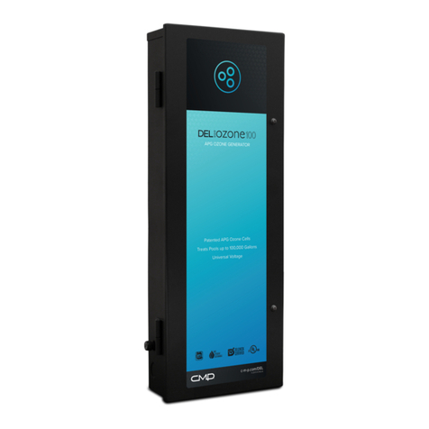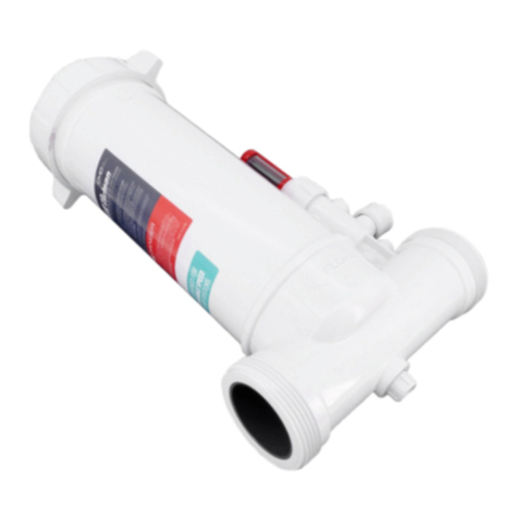
READ AND FOLLOW ALL INSTRUCTIONS
• Read this manual completely before attempting installation. Failure to install in accordance with
the installation instructions could void warranty and result in injury or death.
• All permanent electrical connections should be made by a qualied electrician.
• A pressure wire connector, labeled bonding lugs, is provided on the outside of the unit to
permit connection to a minimum No. 6 AWG (13.3 mm2) solid bonding conductor between this
point and any metal equipment, metal enclosures of electrical equipment, metal water pipes, or
conduit within 5 feet (1.5 meters) of the unit as needed to comply with local requirements.
• Install at least 5 feet (1.5 meters) from wall of pool.
• Follow all applicable electrical codes.
• DANGER ELECTRIC SHOCK HAZARD:Be sure to turn power OFF and disconnect from power
source before any service work is performed. Failure to do so could result in serious injury or
death.
• The AOP Pro must be installed in an outdoor location, or indoors in a forced air ventilated room,
and installed so that the orientation is exactly as shown in Figure 4. Install to provide water
drainage of generator to protect electrical components.
• Mount the AOP Pro so that it is inaccessible to anyone in the pool. Never attempt any servicing
while unit is wet.
• WARNING Short-term inhalation of high concentrations of ozone and long term inhalation of low
concentrations of ozone can cause serious harmful physiological eects. DO NOT inhale ozone
gas produced by this device.
• For your safety, do not store or use gasoline, chemicals or other ammable liquids or vapors near
this or any other appliance.
• To maintain cosmetic integrity, protect this unit from direct prolonged sunlight exposure.
• To reduce the risk of injury, do not permit children to use this product, unless they are closely
supervised at all times.
• ENVIRONMENTAL NOTICE: Hg-Lamp CONTAINS MERCURY. Manage in accordance with
disposal laws.
See: www.lamprecycle.org
• If unit is not operated according to instructions, high dosages of harmful substances may
potentially be released.
• Product has met the requirement of NSF/ANSI 50, Annex H.1 for supplemental disinfection and
is designed for pools that are in compliance with the U.S. Model Aquatic Health Code (MAHC).
Installed ow rates must not exceed max listed ow rates to maintain NSF product listing as well
as ensuring proper microbial performance.
• NSF/ANSI 50, Section 13 disinfection ecacy testing for 3 log (99.9%) or greater of Pseudomonas
Aeruginosa and Enterococcus Faecium. Specic residual levels of EPA registered disinfection
chemicals may be required by the regulatory agency having authority. Product is designed for
supplemental disinfection and should be used with registered or approved disinfection chemicals
to impart residual concentrations.
SAVE THESE INSTRUCTIONS!
IMPORTANT INFORMATION


