CMS SonicShield II User manual

Issue 6

Page 1
Contents
Page 1 - Contents
Page 2 - Welcome
Page 3 - Installation Planning
Page 4 - Transducer Planning
Page 5 - Control unit Planning
Page 6 to 8 - Transducer Installation
Page 9 - Control unit Installation
Page 10 - Battery Cable + Fuse
Page 11 - PSU set up
Page 12 - Transducer fitting
Page 13 - Waterproof Connections
Page 14 - Cable connections
Page 15 - Troubleshooting
CMS Marine
4 St Albans Road
Gloucester
GL2 5FW
+44 (0) 1452 380100
www.cmsmarine.co.uk

Page 2
Welcome
Thank you for choosing CMS Marine to supply your SonicShield Product.
Please ensure you read this installation guide fully before proceeding as correct installation is critical to
the overall success of your Ultrasonic system
If you have any questions or require any help please either contact us on +44 (0) 1452 380100 or
Safety Considerations
WARNING
You MUST install this product in accordance with this installation guide, failure to follow the information
enclosed could result in damage to your vessel or personal injury
You MUST ensure you protect the permanent live connection with a 10 amp Inline fuse. Incorrect
electrical installation could cause irreparable damage to the product or other electrical equipment and
could result in personal injury or damage to the vessel.
If you are not competent working with a 12V or 24V supply please contact a qualified Marine Electronics
installer or contact CMS Marine to discuss installation.
You MUST also be qualified to make any alterations or additions to your 110V –240V AC supply if
necessary. Modifications to your AC system are outside of the scope of this guide.
PLEASE ENSURE ALL POWER IS SWITCHED OFF WHEN CONNECTING OR REMOVING CABLES FROM THE
INTELLIGENT CONTROL UNIT.
IF IN DOUBT PLEASE SEEK PROFESSIONAL ADVICE.

Page 3
Installation
The installation of your SonicShield product is easy if you follow this guide correctly. By following the steps
below in order, you will ensure most efficient use of your time.
Plan the location of your transducers
Plan the location of your control box
Fit the transducer rings
Fit the control box
Run the power and transducer cables
Switch ON.
PLUS Customers will also have to install the alarm system covered in the separate installation guide.
Page 4
Planning - Transducers
Planning the location of the transducers is the MOST important consideration. Incorrect positioning or
installation will result in inefficient cleaning.
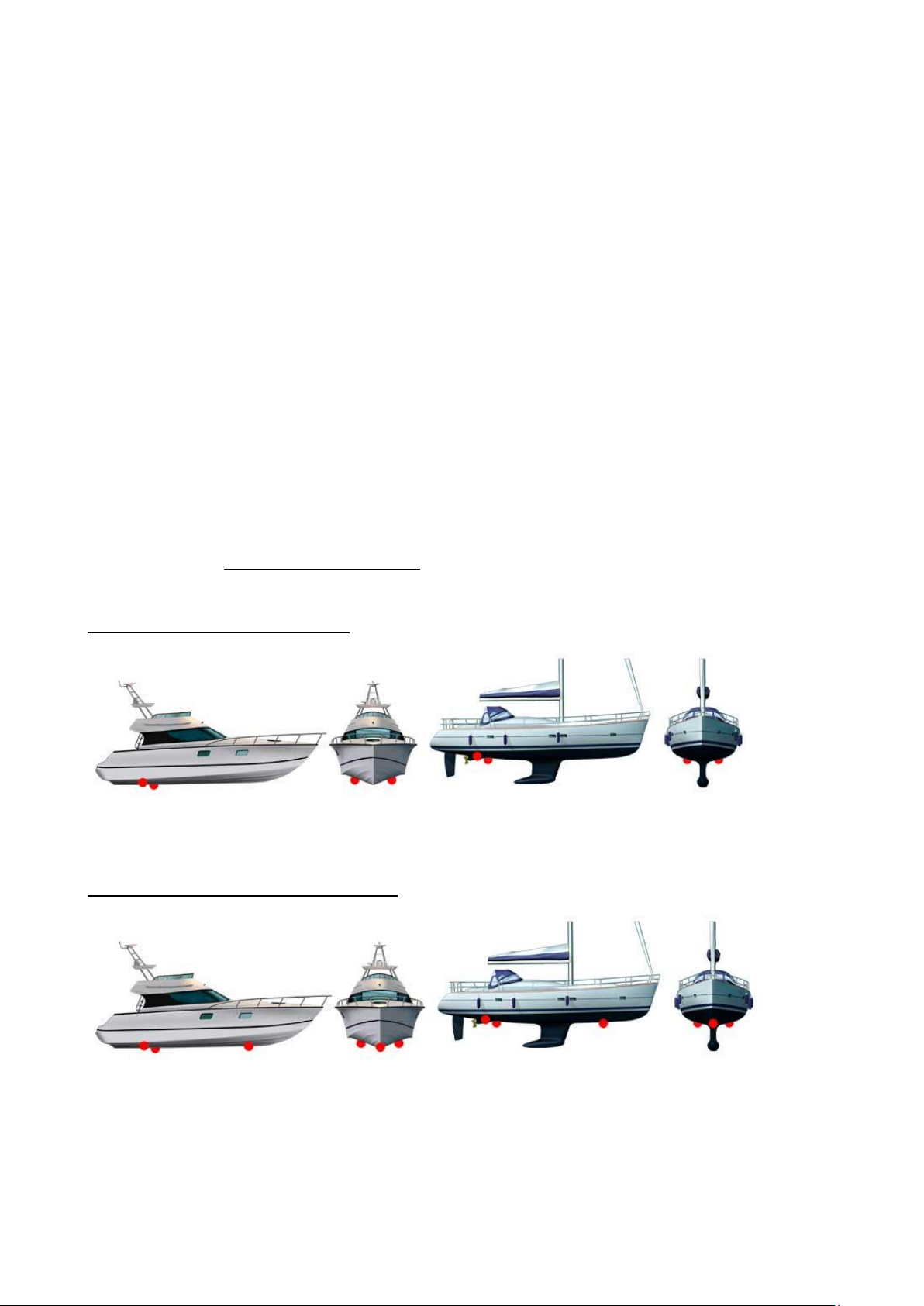
Please see images below for advised installation positions.
You MUST ensure you are installing onto the outer skin of your boat. Modern boats have many false floors
(especially motor vessels). Installation on anything other than the outer skin will severely limit the units
effectiveness.
If you do not think that the Silicon H05RN Transducer cables are long enough to reach your transducers
please contact us to arrange an extension cable.
DO NOT COMPROMISE THE LOCATION OF YOUR TRANSDUCERS BASED ON THE LENGTH OF CABLE.
DO NOT TIGHTLY COIL ANY UNUSED CABLE. –As this could cause interference with other on-board
electronics. If you need to coil the cable we would recommend large, loose coils.
The below is only a rough indication of position. If you would like advice on the optimum position please
call our technical team, as we have experience with many types of boats.
For boats with waterline length <10M
The transducers should be located towards the stern between the propeller and the rudder. One should be
placed to port and the other to starboard approximately 30cm from the centre line.
For boats with waterline length >10M < 20M
The transducers should be located towards the stern between the propeller and the rudder. One should be
placed to port and the other to starboard approximately 30cm from the centre line.
The additional transducer should be located towards the bow. It can be located either port or starboard of
the centre line.
Page 5
Planning –Control Unit
When planning the location for your intelligent control unit you must take into account the following
restrictions.
You Intelligent Control Unit MUST
Be installed above the water line in a dry area
Cabin locker or in the engine bay of a motor launch is ideal
Be located where ALL of your transducer cables can reach
Be located where your battery power cable can reach
Be located near a spare Mains / Shore power socket (110-240v)
Note :- Extension cables can be ordered from us for all cabling.
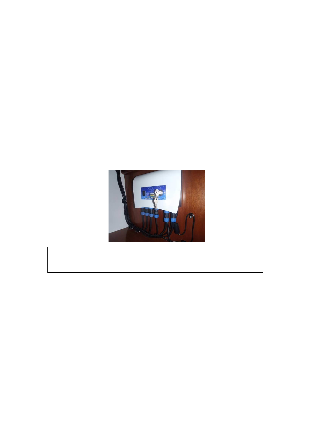
The unit above was installed in the aft port cabin on the outside of a locker, this gave
good access to the main control panel, battery and also the Aft transducers
Page 6
Fitting –Transducers
Remove the transducer from its packaging and place the transducer (with the nut attached) in the area you
plan to install it.
Prepare the surface of the hull using the 80 Grit sandpaper supplied. For best results an orbital sander /
Mutli-tool can be used. Remove gel coat / paint and ensure a smooth flat surface is made in preparation for
the transducer.
ENSURE YOU ARE INSTALLING THE TRANSDUCER IN A SOLID AND FLAT AREA OF YOUR HULL. IT IS VITALLY
IMPORTANT THAT 100% SURFACE CONTACT OF THE TRANSDUCER FACE IS IN CONTACT WITH THE HULL
It is advised to clean the prepared area of the hull and the transducer ring with an alcohol based solvent i.e
Acetone (Not supplied). PLEASE ENSURE YOU TAKE NOTE OF THE MANUFACTURERS SAFETY
INSTRUCTIONS WHEN USING THESE PRODUCTS.
Place the transducer assembly on this newly prepared area and draw around the ring to give you a guide
for the epoxy later in the assembly.
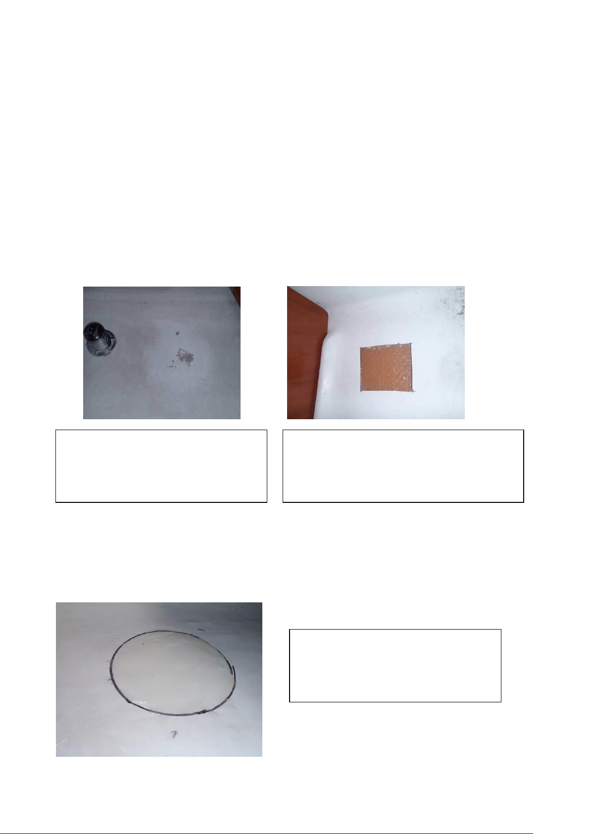
This area was prepared for the bow
transducer using a sander. The more paint
you remove the better the adhesion will be.
This area had a false floor in the starboard aft
cabin and so required cutting to access the GRP
hull. We used a Fein Multimaster tool with the saw
attachment that was ideal.
After preparing the hull area, place the
transducer and nut in the proposed position
and draw around the outside of the nut to
give you a guide.
Page 7
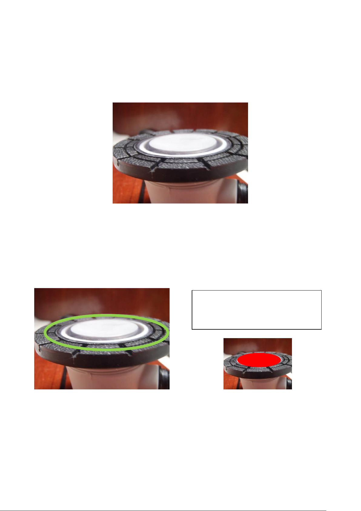
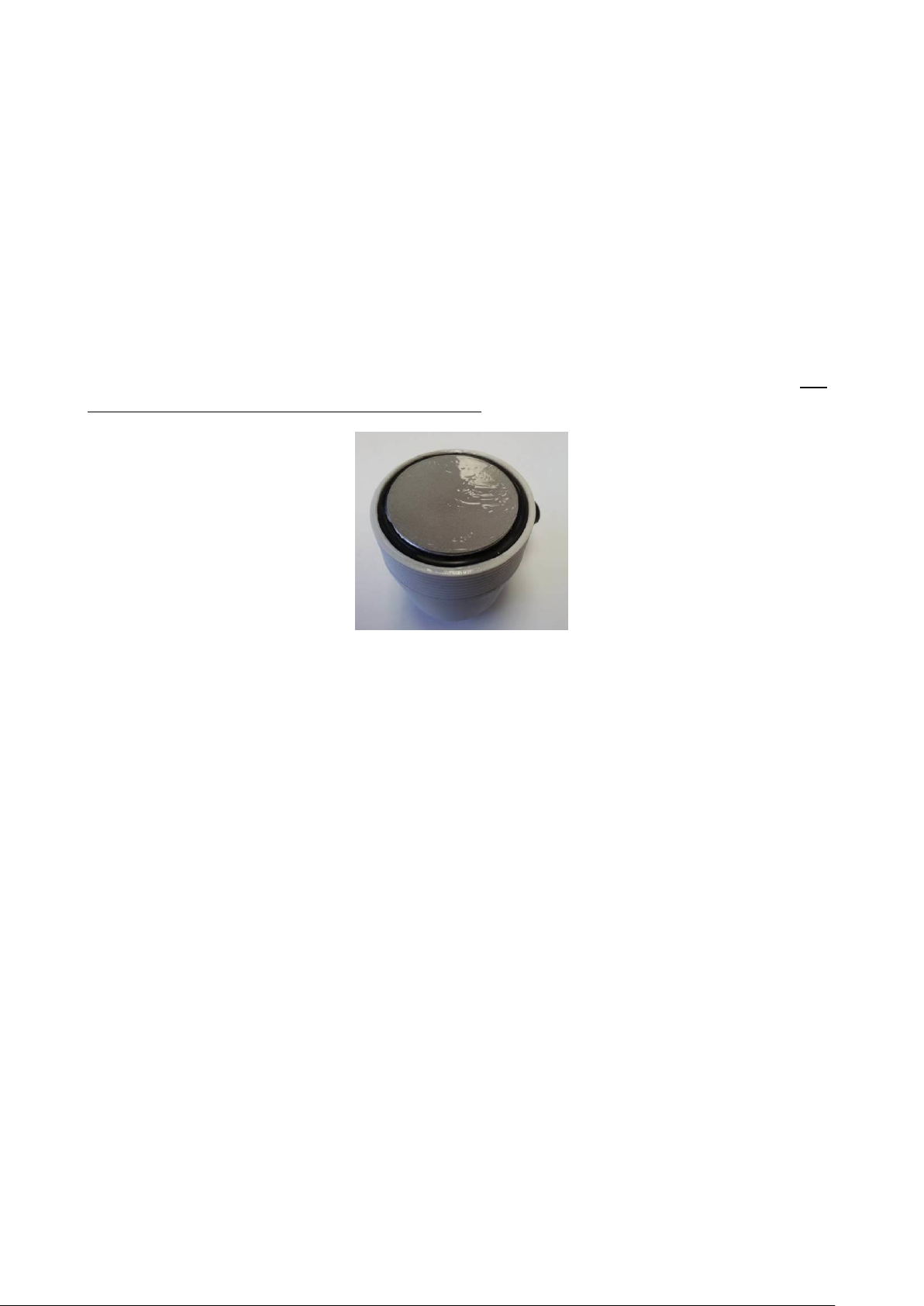
Once you have prepared the hull you are now ready to apply the adhesive plastic disc. Screw the
transducer into the ring until it sits slightly proud of the nut. Peel off the white backing paper and fix the
plastic disc to the centre of the transducer face. Smooth the edges of the disc so that they are touching the
solid black ring of the transducer nut as show below.
The purpose of the plastic disc is to ensure you have a solid contact to the hull of the boat. Later in this
guide you will be applying epoxy resin to the boats hull and this plastic disc will protect the transducer face
from the epoxy resin.
Using the epoxy resin supplied you will now need to apply epoxy to the transducer ring ONLY, ensuring you
DO NOT apply any epoxy to the plastic covering, applying epoxy to the plastic covering will create bubbling
/ rippling which will decrease effectiveness. Be aware of the rapid setting time of the epoxy resin and only
mix enough for immediate use.
Once you have applied the epoxy to the ring you can now apply the epoxy to the hull area (as shown on the
next page). Using the guide you drew earlier apply a generous amount of the epoxy ensuring you cover the
entire area of the hull where the transducer and nut will be located. Try to ensure the epoxy resin is as level
as possible.
Apply epoxy to the ring area only
(highlighted Green), avoiding contact with
the plastic covering (highlighted red below)

Page 8
Once you have a good covering of epoxy on the hull and the nut you will now need to carefully place the
transducer onto the hull.
It is important at this stage that you do not move (twist, lift, etc) the transducer once the plastic covering
over the transducer face has made contact with the epoxy on the hull.
Place the transducer assembly onto the prepared hull surface, apply direct pressure to the transducer and
if possible apply some weight that can be left in place during the curing process.
You DO NOT need to remove the plastic disc from the assembly after the epoxy has cured.
Repeat this process from the rest of the transducers supplied with your kit.
THIS IS THE MOST IMPORTANT PROCESS YOU WILL UNDERTAKE TODAY AND SO YOU MUST ENSURE YOU
GET IT RIGHT. IF YOU HAVE ANY QUESTIONS OR REQUIRE ANY SUPPORT CALL US ON +44 1452 380100.
Apply glue generously to the hull area
ensuring you cover an area large enough to
accept the ring and transducer face.
You are aiming to get a good even covering
over the whole transducer area to ensure
the transducer face has good contact with
the hull through the epoxy resin.
Example of a transducer that has been left
in place to cure. This is how your transducer
should look before you move to the next
transducer.

Page 9
Fitting –Control Unit
Using the template provided in your installation kit, carefully make pilot holes using a 2mm drill bit.
Using the x4 screw provided, mount the control box to your chosen location.
NOTE : When drilling / screwing into boat surfaces check that there are no cables or pipes on the opposite
side of the surface. Check that once installed the screws will not protrude through the surface.
Remember that you should ensure that the control box is mounted above the waterline.
PLEASE ENSURE YOU HAVE ACCESS TO THE UNDERSIDE OF YOUR CONTROL UNIT TO ALLOW FITMENT OF
THE CONNECTORS.
Fitting –Transducer Cables
The transducer cables supplied are made from marine based silicon and will withstand any water or
temperature fluctuations during normal operation.
It is suggested that where possible you follow any current cabling or trunking to aid your installation of
cables.
Starting at your transducer work the cable back to control unit.
DO NOT CONNECT ANY OF THE CABLES TO YOUR UNIT AT THIS STAGE.
DO NOT COIL ANY TIGHTLY UNUSED CABLE, LARGE LOOSE COILS ARE OK.
IF YOU REQUIRE LONGER CABLES TO REACH YOUR CONTROL UNIT PLEASE CONTACT US FOR EXTENSION
CABLES
If you need to drill through any watertight bulk heads or lockers ensure you use a cable gland to ensure
they remain watertight. If you require any support or advice at this stage please contact our technical team
who will be more than happy to offer some advice.
Page 10
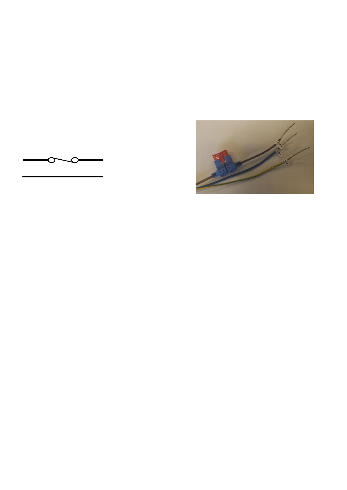
Fitting –12V / 24V Battery supply.
You will need to ensure a permanently live supply from your battery to the control unit.
CMS Marine advise making a direct connection to your battery. YOU MUST install a 10 AMP inline fuse as
close to the battery on the live supply as possible. Failure to install the fuse could result in damage to your
control unit and will invalidate your warranty.
We supply 3 Core cable to allow installation on either 12v or 24v DC. Please ensure you use the correct
wires for your boats DC configuration.
PLEASE ENSURE THAT YOU ALSO CONNECT THE ‘BARE’ END OF THE BATTERY CABLE TO THE CORRECT
POLARITY ON YOUR BATTERY. CROSS POLARITY WILL CAUSE DAMAGE TO YOUR UNIT.
BROWN 24v +VE
BLUE 12v +VE
GREEN/YELLOW 0v -VE
GREEN/YELLOW -VE
BROWN 24v +VE / BLUE 12v +VE

Page 11
Fitting –Power Supply Unit.
All SonicShield units are supplied with a Mains / Shore 110-240V Power supply unit. Also included is an EU
and UK Power lead.
Select the correct lead for your boat type and plug the Fig 8 end into the Power Supply Unit.
Using the supplied Velcro, attach the power supply unit to a solid surface, ensuring this is located in an area
above your boats water line.
Note
The control unit is intelligently controlled and is able to accept both the 12V/24V supply from your battery
and the shore power supply at the same time. It will detect which power supply to use and will only draw
current from one source at any time.
For example if shore power is available it will always use this supply. It will only switch to the 12V/24V
battery supply if the shore power is removed. If you intend to only use the shore power then there is no
need to install the 12V/24V battery supply, we do not advise running from only AC as if shore power is
removed you will not have any cleaning.
It is not necessary to install the AC for the system to run.
Page 12
Fitting –Cable to transducer
Once the epoxy resin has fully cured (approx 24 Hours) you will be able to unscrew the transducer from the
ring. This should be possible by hand only.
If however you are unable to loosen the transducer by hand you may need to give the transducer a slight
tap with a mallet to loosen any epoxy resin excess. EXCESS FORCE IS NOT REQUIRED TO REMOVE THE
TRANSDUCER. IF YOU ARE HAVING PROBLEMS PLEASE CONTACT US FOR FURTHER ADVICE.
Apply a small amount of silicon grease to the face of the transducer. You will only need a light skin approx
1mm thick. The silicon grease is used to aid acoustic coupling of the transducer unit to your boats hull. Too
much grease will decrease the effectiveness of the unit.
Screw the transducer into the ring until hand tight.
DO NOT OVERTIGHTEN THE TRANSDUCER AS THIS MAY CAUSE THE EPOXY TO CRACK AND WILL
DECREASE THE EFFECTIVENSS OF THE UNIT.
Please note that after approximately 24hrs of running the silicon will have settled and your transducers may
need a further ¼ turn to ensure they are tight to the hull. If the transducers are not tight they will not be
acting at maximum efficiency.

Page 13
Waterproof connections
All of the connectors are IP68 rated. To protect against any moisture / condensation build up within
connector we advise applying a small amount of silicon grease to ALL of the connectors as detailed below.
Apply only a small amount of silicon grease (approx. ½ pea or 0.5g) to the plug, ensure the grease is evenly
spread over the connection. Then connect plug to socket.
We advise checking the silicon grease on the transducer connectors every 6 Months.
Repeat this process from the rest of the transducers supplied with your kit.

Page 14
Fitting –All cables to the control unit
Please use the picture below to correctly connect the cables to the control unit. N.B If you have purchased
a system with the PLUS option you will have more connections and need to refer to the PLUS Installation
and Operation Guide.
YOU MUST CONNECT THE TRANSDUCER CABLES BEFORE CONNECTING ANY POWER TO THE UNIT
Firstly connect the transducer cables, ensure the nuts are secure to prevent them from becoming
disconnected.
Connect the power supply unit to the control box.
Connect the battery cable to the control box.
Plug the power supply unit into the mains / shore power socket.
The unit will run a test and within 15 seconds you will see the transducer lights start and your unit will be
running. The system will then run in ‘Learning’ mode for between 3-4 minutes. During this time the system
will determine the number of transducers connected. If you add a transducer to your system you will need
to power the system off at the DC and AC to re-enter the learning mode required to add the transducers.
Your SonicShield Intelligent antifouling unit is now fully installed.
Power Control –Sleep Mode
We advise running the Ultrasonic cleaning at all times. The system is designed to deter the build up of algae
and therefore if allowed to build up on your hull the systems effectiveness will be decreased.
If you need to turn the system off then this should only be performed via the On/Off switch on the front of
the main control unit. The On/Off switch is on a time delay to protect against prolonged periods of
inactivity.
A single press of the switch will ‘sleep’ the system for 12 hours. The system will automatically turn back on
after the 12 hour period. Pressing the switch again at any point during the 12 hour period will cancel the
sleep mode and the system will resume running as normal.

Page 15
Troubleshooting
Power Light
Solid Blue = Unit has power
Status Lights
Solid Green = Mains / Shore power operation
Flashing Green = 12/24V battery operation
Flashing Red = 12/24V battery low
Solid Red = Fault - High Temperature
Solid Red with LDR Fitted = System cleaning Deactivated
Transducers Lights
Flashing Yellow = Transducers in operation
Yellow Off = Transducers not running.
Flashing Red = Fault –No current or High current detected on Transducer
5 Flashes and 5 Beeps = Fault –System off due to Error –CONTACT CMS MARINE for Advise
If you see any other combination of lights or you do not have any lights, please contact us.
Maintenance
No regular maintenance of the transducers or system is required.
With all marine electronic installations we advise checking cabling and connections on a periodic basis to
ensure no damage has occurred.
Every 6 Months we would advise checking the transducers are tight and if required a fresh layer of silicon
grease applied to the transducer face and connector. Please note that if you do reapply the additional
silicon that you will need to check the transducers after 24 Hours as a further ¼ turn may be required to
ensure the transducers are tight to the hull.
Thank you
CMS Marine
This manual suits for next models
1
Table of contents
Popular Marine Equipment manuals by other brands


Yanmar
Yanmar SD25 Operation manual

Boss Audio Systems
Boss Audio Systems MR1308UAB user manual

JRC
JRC Alphatron Marine AlphaTurn Installation and operation manual

Seastar Solutions
Seastar Solutions HA5456 installation instructions

Roswell
Roswell Area 53 Bimini Series Installation & Usage Instructions

E2S
E2S IS-AL105NL instruction manual