_______________________________________________________________________________________________________________________________
Europea
n Safet
y Syste
ms Ltd.
Impress House, Mansell Road, Acton, London W3 7QH [email protected] Tel: +44 (0)20 8743 8880 www.e2s.com Fax: +44 (0)20 8740 4200
Document No. IS 4501 Issue G 13-01-20 Sheet 2 of 6
2) The equipment may be used in zones 0, 1 and 2
with flammable gases and vapours with apparatus
groups IIA, IIB & IIC and with temperature classes
T1, T2, T3 and T4.
3) The equipment is only certified for use in ambient
temperatures in the range -40oC to +60oC and
should not be used outside this range.
4) The certificate number has an ‘X’ suffix, which
indicates that the certificate contains one of more
special conditions for safe use. Those installing or
inspecting the equipment should refer to this section
of the certificate.
5) The equipment has not been assessed as a safety-
related device (as referred to by Directive 94/9/EC
Annex II, clause 1.5).
6) Installation of this equipment shall be carried out by
suitably-trained personnel in accordance with the
applicable code of practice.
7) Repair of this equipment shall only be carried out by
the manufacturer or in accordance with the
applicable code of practice.
8) The certification of this equipment relies on the
following materials used in its construction:
Enclosure: ABS Plastic
If the equipment is likely to come into contact with
aggressive substances, then it is the responsibility of
the user to take suitable precautions that prevent it
from being adversely affected, thus ensuring that the
type of protection is not compromised.
“Aggressive substances” - e.g. acidic liquids or
gases that may attack metals, or solvents that may
affect polymeric materials.
“Suitable precautions” - e.g. regular checks as part
of routine inspections or establishing from the
material’s data sheet that it is resistant to specific
chemicals.
SPECIAL CONDITIONS FOR SAFE USE (as stated on the
EC Type Examination Certificate SIRA 04ATEX2301X)
The equipment shall only be supplied via Terminals + w.r.t.
Terminals - from a barrier having a maximum open circuit
voltage Uo that is < 28 V and a maximum short circuit current
Io that is < 93 mA, where Io is resistively limited. The barrier
shall be ATEX certified by a notified body.
The total capacitance connected to terminals + wrt – (i.e. the
capacitance of the cable plus any other capacitance) shall
not exceed 83nF.
The enclosure is non-conducting and may generate an
ignition-capable level of electrosatic charges under certain
extreme conditions. The user should ensure that the
equipment is not installed in a location where it may be
subjected to external conditions that might cause a build-up
of electrostatic charges on non-conducting surfaces,
additionally, cleaning of the equipment should be done only
with a damp cloth.
The equipment has an ingress protection rating of IP66;
however, if it has been supplied without a cable entry device,
then the user shall ensure that the device that is fitted will
provide an ingress protection that is appropriate to the
environment in which it is installed i.e. IP20 or better.
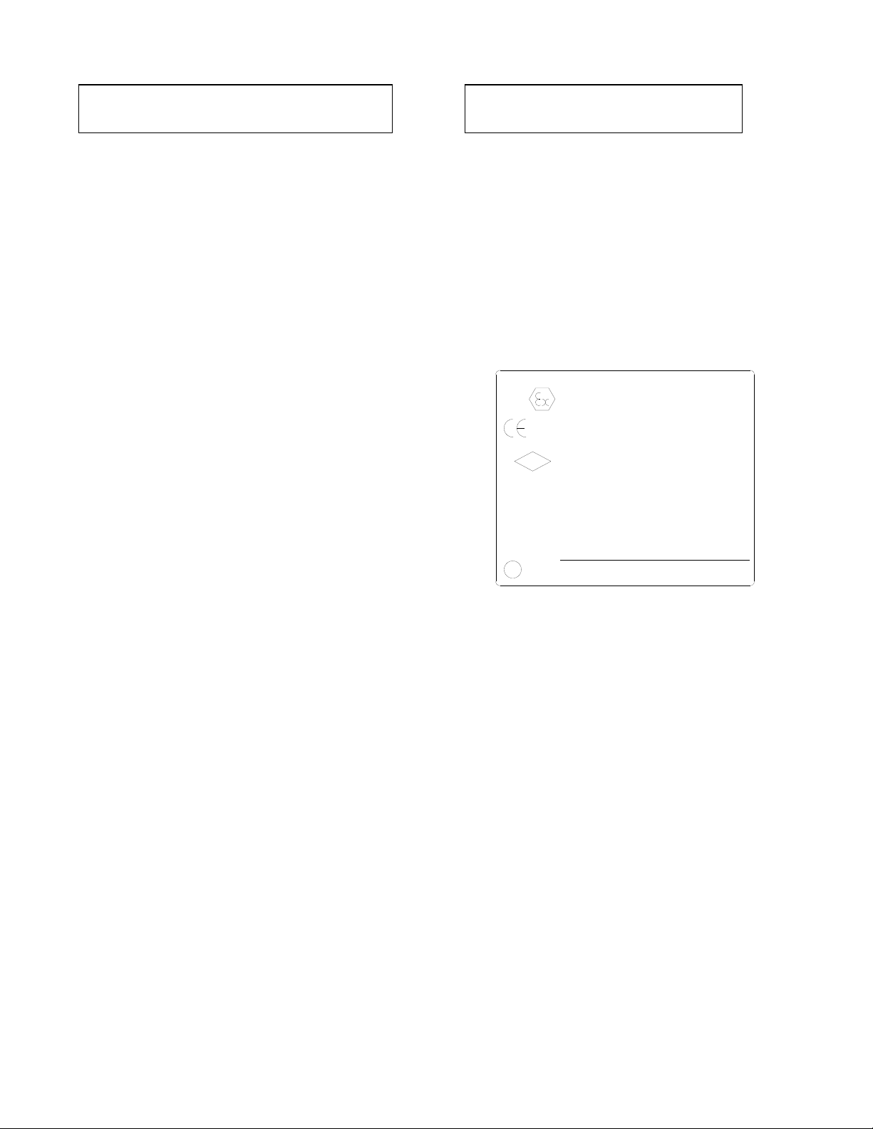
4.2 Zones, Gas Groups and Temperature Classification
The IS-A105N sounder has been certified Ex ia IIC T4 Ga.
When connected to an approved system it may be installed
in:
Zone 0 explosive gas air mixture
continuously present.
Zone 1 explosive gas air mixture likely to occur in
normal operation.
Zone 2 explosive gas air mixture not likely to occur,
and if it does, it will only exist for a short time.
Be used with gases in groups:
Group A propane
Group B ethylene
Group C hydrogen
Having a temperature classification of:
T1 450ºC
T2 300ºC
T3 200ºC
T4 135ºC
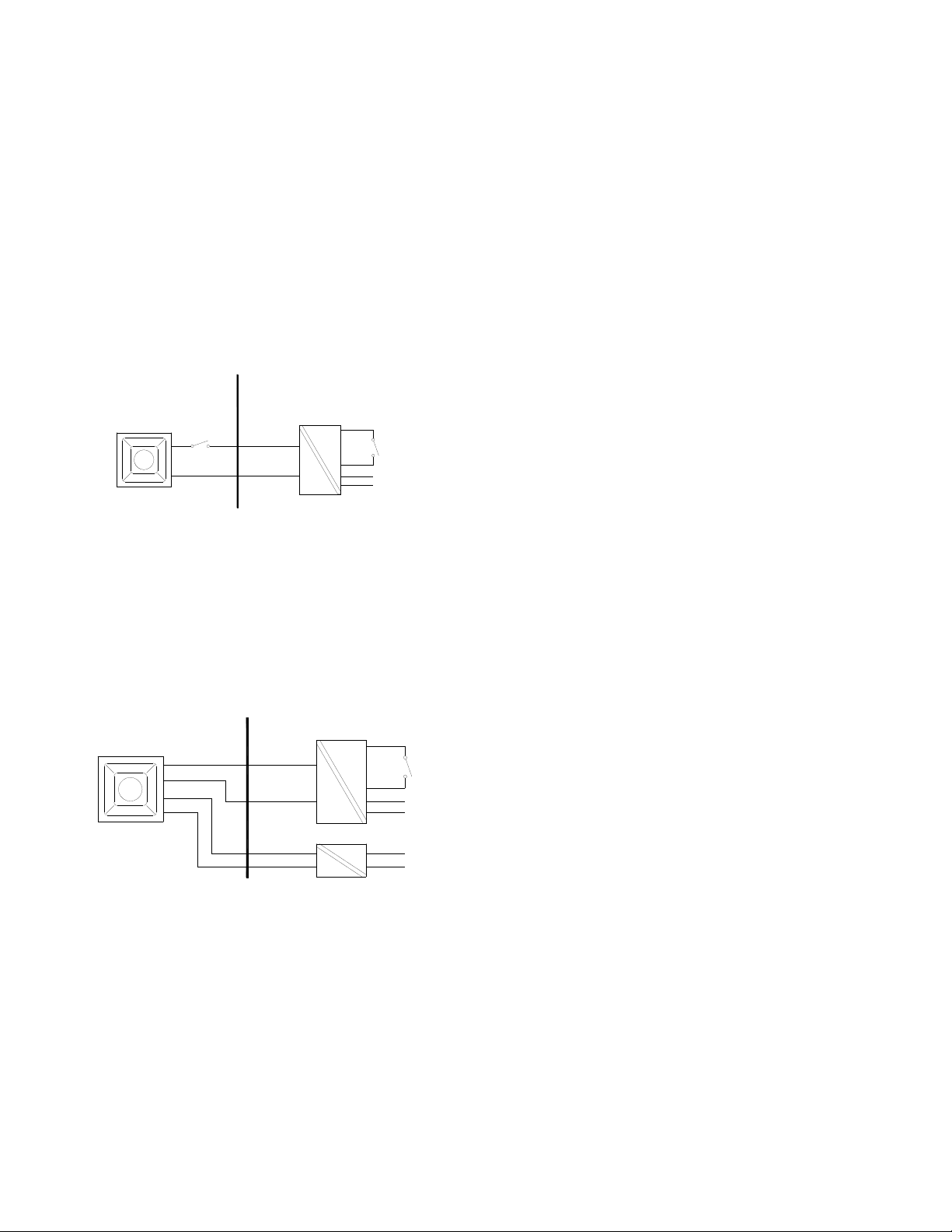
4.3 Terminals + and -
Power is supplied to the sounder via the + and – terminals
which have the following input safety parameters:
Ui = 28V
Ii = 93mA
Pi = 660mW
Ci = 0 Li = 0
The IS-A105N sounder may be powered from an ATEX
certified Zener barrier or galvanic isolator which have output
parameters equal to or less than 28V, 93mA and 660mW
where Io is resistively limited. The cable parameters stated
on the selected Zener barrier or galvanic isolator certificate
must be observed.
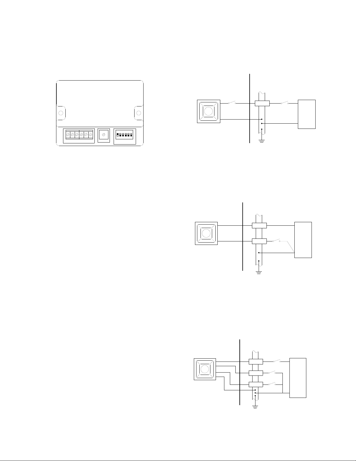
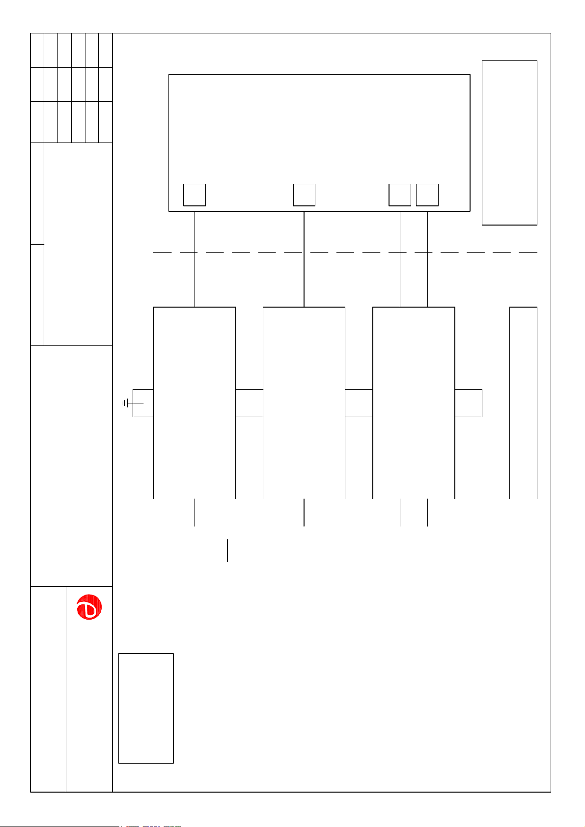
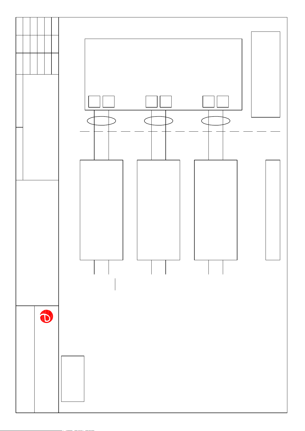
Up to three IS-A105N sounders can be connected in parallel
and powered from a common barrier or isolator. Connecting
two sounders in parallel will reduce the output from each by
about 3dB. Three sounders should only be powered from a
common supply when the maximum supply voltage is
available.
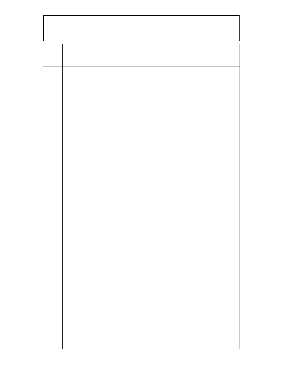
4.4 Terminals S2 and S3
When terminals S2 or S3 are connected to 0V (- terminal) the
sounder output tone changes to the second or third stage
alarm respectively. The input safety parameters for these
terminals are:
Ui = 28V
Ii = 0mA
Because the permitted input current is zero, these terminals
may only be connected to a diode return barrier, an