Sonardyne 7986 User manual

OM-7986
Operating Manual for
Type 7986 Lightweight
Release Transponder (LRT)
Head Office
Sonardyne International Limited
Blackbushe Business Park
Yateley, Hampshire
GU46 6GD United Kingdom
T. +44 (0) 1252 872288
F. +44 (0) 1252 876100
www.sonardyne.com

OM-7986
Page 1 of 23 Issue A - Rev 8
OM-7986
OPERATING MANUAL
TYPE 7986 LIGHTWEIGHT RELEASE TRANSPONDER
ISSUE A
REVISION 8
Prepared by : D J Baker
Authorised by : N D Street
Date : 21st November 2010
S O N A R D Y N E I N T E R N A T I O N A L L I M I T E D
Blackbushe Business Park Yateley Hampshire GU46 6GD United Kingdom

OM-7986
Page 2 of 23 Issue A - Rev 8
C O N T E N T S
1. INTRODUCTION
2. OPERATION
2.1 Initial Checks
2.2 Programming the Unit
2.3 Measuring the Battery Voltage
2.4 Loading the Release Mechanism
2.5 Testing the Release Mechanism Prior to Deployment
2.6 Safe Working Loads
2.7 Deploying the LRT
2.8 Ranging to the LRT
2.9 Releasing the LRT in Water
2.10 Using the Rope Canister
3. MAINTENANCE
3.1 Battery Pack Replacement
3.2 Replacing the PCB, Release Endcap and Transducer.
3.3 General Maintenance
4. SPECIFICATIONS
4.1 LRT Specifications
4.2 Rope Canister Specifications
4.3 Large Rope Canister Specifications
5. DRAWINGS
5.1 LRT Outline Drawing
5.2 Release Nut Manufacturing Drawing
5.3 Rope Canister Outline Drawing
5.4 Large Rope Canister Outline Drawing
6. SPARES LIST
6.1 LRT
6.2 Rope Canister
7. APPENDIX
7.1 Address/Frequency Group Conversion Table
Fig.1 – Type 7986 Lightweight Release Transponder (LRT)

OM-7986
Page 3 of 23 Issue A - Rev 8
A M E N D M E N T R E C O R D
All amendments and additions will be issued with a new copy of this sheet
recording the history of amendments
Issue Revision Date Comments Section Page
A 0 08.09.00 Initial Issue All All
A 1 20.09.02 Additional notes added on release load
CN 7418 All All
A 2 21.07.03 CPN number for Release Mechanism
Endcap in Spares List was 641-050 and
has been amended to 641-1050
All All
A 3 11.04.06 Update to include rope canister variants. All All
CN 8951
A 4 19.05.06 Additional parameters for 4.1 17
“Max Listening Life” CN 9006
A 5 21.02.07 Amendment to stock code for shackle in All All
Section 6 - CN 9306
A 6 24.09.08 Add Tilt indication version 7986-000-06 1, 2 4, 7, 10
CN 9937
A 7 21.07.09 New pictures & rope canister details All All
CN 10328
A 8 21.11.10 Add rope canister specs All All
CN 10929

OM-7986
Page 4 of 23 Issue A - Rev 8
1. INTRODUCTION
The Type 7986 Lightweight Release Transponder (LRT) has been designed for use in
continental shelf waters to water depths of 500 meters. The unique design enables small
strings of instruments or seabed devices to be deployed without a surface marker and
automatically recovered upon acoustic command from the surface.
The transponder has been designed to be low-cost, enabling acoustic releases to be
economically and operationally viable in applications where they have traditionally not been
used. At the same time the unit is extremely reliable and rugged, the design being based on
Sonardyne’s successful and well proven Ocean Bottom Seismic positioning system.
The transponder is designed to be small, lightweight and long-life, with field replaceable
alkaline or lithium battery packs giving a listening life from 18 to 51 months.
The unique positive-action release mechanism ensures high reliability even in high bio-
fouling areas. The plastic material used for the release ‘nut’ is impregnated with lubricant to
limit bio-fouling.
The unit is designed to a Safe Working Load (S.W.L) of up to 125kg.
On the deck, using the Type 7967 Surface Unit, the transponder can be programmed in the
field to one of over 3600 unique acoustic identities.
Using various surface systems the transponders can be interrogated to determine the slant
range from the vessel to the transponder. This enables the operator to confirm the
transponder is operational and within range. If the unit has been dragged from its original
location it also enables the transponder to be relocated.
To release the transponder the operator must send 3 unique and secure messages to the
transponder. Upon receipt the transponder replies and activates the motor to turn the
release shaft. This drives out the release ‘nut’ breaking out any bio-foul material and enables
the unit to return to the surface under its own buoyancy.
The transponder is compatible with Sonardyne’s Homer-Pro system, a hand-held relocation
system for use by divers. The unit gives range and direction to swim to guide a diver towards
the transponder. ROV-Homer, the remote vehicle mounted version, can also be used in a
tow-fish for relocation sweeps.
The transponder is also compatible with Sonardyne’s low-cost Long Base Line navigation
system (ROV-Trak) which enables divers or ROVs to be accurately positioned and navigated.
As an optional extra the LRT can be retro-fitted with a variety of rope canisters. On release,
high strength recovery line is deployed from a canister on the side of the LRT, currently there
are options up to a maximum of 160 m. It should be noted that the recovery line may have a
lower safe working load than the LRT.
The 7986-000-06 version of the LRT is fitted with a Tilt indication feature, see label. The
ranging behaviour changes if the unit is tipped more than 30 degrees from vertical, as it will
only reply to alternate ranging interrogations if it is tilted.

OM-7986
Page 5 of 23 Issue A - Rev 8
2. OPERATION
2.1 Initial Checks
On receipt of the LRT from Sonardyne the unit will be in a fully working condition, with the
internal battery pack fitted and the unit on, unless special shipping regulations dictate that the
battery pack is shipped separately. If the battery pack has been shipped separately then
refer to section 3.1 – Battery Changing.
2.2 Programming
The unit will be programmed to the default acoustic identity which is Address 005 Reply 5
(51). Unless the default identity is to be used you will need to program the unit to an identity
of your choice, ensure that the same identity is not already in use with other LRTs that you
have or that are operational within the area.
To program the transponder use the Type 7967 Surface Unit, select the interrogation address
(1 to 401) and then the reply code/frequency (1 to 9). Place the programming loop around
the black transducer as shown below and press the PROGRAM button. The surface unit will
program and then test the transponder, it will display PASS and beep once to confirm
successful programming. FAIL will be display and no beep will be heard if unsuccessful. An
additional test can be carried out by pressing the TEST button.
NOTE - if the LRT has the Tilt feature fitted, every other Program operation will give a FAIL
reply if the unit is tilted beyond 30 degrees.
Follow the instructions in the OM-7967 Manual or the short-form instruction sheet inside the
lid of the box.
The programmed acoustic identity is stored in non-volatile memory, therefore if the battery is
disconnected for any period of time the programmed identity is not lost.
INCORRECT
CORRECT
Fig.2 – Programming loop attached around the transducer
NOTE - For use with Sonardyne’s Homer-Pro and/or ROV-Homer system address groups
004 to 013 only should be used, all reply frequencies (81 unique IDs). See Appendix 7.1.
You can only program the transponder using the loop not the remote transducer. This
interlock ensures that no transponders already deployed in the water are accidentally
programmed.

OM-7986
Page 6 of 23 Issue A - Rev 8
With a waterproof and scratch-proof label or pen mark the acoustic identity clearly on the
housing of the LRT. Make a permanent note of the transponder identity (& serial number if
required) on file with the associated GPS drop position.
WARNING – Once deployed there is no way to automatically read a transponder’s
programmed identity. All identities must be cycled through whilst checking for a response to
determine the programmed identity.
2.3 Measuring the Battery Voltage
The internal battery voltage of the transponder can be read by connecting the loop around
the transducer and pressing the BATTERY button. The transponder reads its own battery
voltage and sends an acoustic telemetry message to the surface unit.
The voltage is accurate to 0.25 volts.
BATTERY TYPE vs
Voltage/Life/Source Level
Alkaline
10 cell
(641-2414)
Lithium
2 x 4 cells
(640-8515)
Lithium
TX & RX
(640-8864)
Initial Voltage (volts) 16.0 14.1 14.1
Start Voltage (volts) 15.0 14 14
End of Life (volts) 11.25 N/A N/A
Capacity (mAh) ~2500 ~4200 ~6300
Typical Listening Life(months)
See note below 18 34 51
Source Level (dB re1uPa@1m)
See note below 187-188 186-187 186-188
Typical Listening Life = the maximum battery life due whilst listening only.
(this assumes the transponder is only rarely interrogated or released)
2.4 Loading The Release Mechanism
NOTE – Grease the stainless steel shaft of the release mechanism and the release ‘nut’
thread with underwater grease prior to loading the mechanism. Although the glass re-
enforced plastic is already impregnated with lubricant, this significantly reduces the friction.
This in turn reduces the starting torque on the motor, and therefore significantly increases the
release load reliability of the LRT.
You can only load the release mechanism using the loop. You cannot load the release
mechanism using the remote transducer.
Connect the loop around the transducer. Turn the right hand most dial (FREQUENCY) to the
LOAD position. Press the green button marked BATTERY/LOAD.
The surface unit will send a telemetry command to the transponder to rotate the shaft for 60
seconds. During this period insert the ‘nut’ onto the shaft ensuring it engages cleanly.
Loading the nut will take approximately 30 seconds before it bottoms against the endcap.
Whilst loading the release mechanism is set to low-power and the current drawn by the motor
is automatically sensed to detect when the nut bottoms against the endcap.
When high current is sensed, indicating the nut has been fully loaded, the release
mechanism will reverse direction for 1.5 seconds and wind the nut off the endcap. This is to
minimise the power required on start-up to release the nut in operation.

OM-7986
Page 7 of 23 Issue A - Rev 8
Fig.3 – Loading the release nut into the release mechanism
WARNING – Ensure the nut is not engaged at an angle as this may cause the nut to cross-
thread causing damage, replace the nut if this happens. If the nut becomes cross-threaded
during loading the release mechanism may current-limit and stop before the nut bottoms
against the endcap. Always watch the nut being loaded and ensure that the nut stops
against the endcap during loading, or the SWL of the unit may be compromised.
Once significant load has been applied to a release nut then it should be replaced.
When operating the rope canister ensure the nut is loaded in the correct orientation, see
section 2.10.
2.5 Testing the Release Mechanism Prior to Deployment
The programming loop communicates with the LRT electrically. It cannot test the acoustic
output from the transducer, so it is always recommended that the remote transducer is used
to test the operation of the LRT in water.
WARNING – Before deployment in water ensure that the red pressure-relief valve in the
release mechanism endcap is pushed home (note it is also sprung loaded).
Load the release nut and attach the LRT and nut by a short line and deploy in greater than 1
metre depth of water (a bucket can be used if necessary). Deploy the remote transducer
near to the LRT in the water and connect to the surface unit.
On the surface unit select the LRTs programmed acoustic identity, address group and
frequency. Press the TEST/RANGE button, the surface unit will interrogate the transponder
and listen for the reply. If a valid reply is received then the range in metres, if greater than
0.6m, will be displayed and a beep will be heard. If less than 0.6m away then ‘PASS’ will be
displayed. If no valid range is received then ‘FAIL’ will be displayed and no beep will be
heard.
NOTE - if the LRT has the Tilt feature fitted, only every other interrogation will give a Range
reply if the unit is tilted beyond 30 degrees.

OM-7986
Page 8 of 23 Issue A - Rev 8
To release the LRT, simultaneously press and hold down for >1 seconds the PROGRAM and
BATTERY/LOAD buttons. ‘EnbL’ will be displayed indicating the transponder will be enabled.
The first unique release command will then be sent to the transponder. If the transponder
receives the command it will reply and the range in metres will be displayed and a beep heard.
The operator then has 20 seconds time limit within which to send to the second release
command to the transponder. Again simultaneously press and hold down for >1 seconds the
PROGRAM and BATTERY/LOAD buttons. ‘Set’ will be display indicating the release
mechanism will be set. The second release command will be sent, again the transponder will
reply and the range will be displayed.
The surface unit then automatically sends a third unique release command to confirm the
release action, ‘rEL-’ will be displayed and then the range in metres. The surface unit then
displays ‘-run’ indicating that the release mechanism is turning, it takes approximately 30
seconds for the nut to be released, the surface will display ‘donE’ to indicate the release is
complete.
With all three of the above commands sent, if no reply is received from the LRT then the
surface unit will display ‘FAIL’. If the final ‘rEL-‘ command results in a ‘FAIL’ the timer will still
run but will display ‘----‘. It is permissible in this circumstance to again press and hold down
the PROGRAM and BATTERY/LOAD buttons to repeat the ‘Set-‘ ‘rEL-‘ sequence.
NOTE – Due to acoustic ambient noise at the surface, typically generated by the vessel, the
reply signal from the LRT to the surface is more difficult to detect than the down going
release command to LRT on the seabed. This therefore means that in difficult environments
although the reply signal from the transponder is not received (No Reply) the transponder
may have heard the release command and will therefore release. If No Reply is indicated it is
therefore still worth while continuously transmitting the release command to recover the LRT.
Whilst in the ‘–run’ mode the surface unit will not allow any other commands. However the
surface can be reset in this mode by switching to the ‘RS232’ position and back again to the
selected address. By pressing the TEST/RANGE button it is then possible to range to the
LRT. As the range starts to decrease this will indicate that the LRT is rising to the surface.
Recover the LRT from the water and ensure that nut has been released from the mechanism.
Note that if testing in very shallow water the acoustic performance may be poor, due to the
acoustically reverberant environment. If so, try re-testing in deeper, more open waters.

OM-7986
Page 9 of 23 Issue A - Rev 8
Fig.5 - LRT with the rope canister attached and flotation buoys,
surface command unit and remote transducer
2.6 Safe Working Loads
The Type 7986 LRT has a Safe Working Load (SWL) of 125kg. This is defined as the
maximum recommended working load. This is set as a quarter (1/4) of the Breaking Load
and allows for factors such as corrosion, fatigue, shock loads, harmonic loads, manufacturing
and material variations. S.W.L = 125Kg
Release Load
The LRT has a maximum release load of 125kg. This is the maximum in-line load that the
whole assembly can release whilst guaranteeing safe and reliable operation. Note that as
the load is released in water, this is normally determined by the maximum up-thrust from
buoyancy.
WARNING – the maximum release load of 125kg only applies if the shaft and nut are coated
with underwater grease and the correct battery pack is used, see below.
RELEASE LOADS (Kg)
vs Battery Type & Life
START
Nut
Greased
START
Nut NOT
Greased
END
Nut
Greased
END
Nut NOT
Greased
Alkaline 10 Cell (641-2414) 125 100 125 50
Lithium 2 x 4 Cell (640-8515) 125 100 125 50
Lithium TX & RX (640-8864) 125 100 125 50

OM-7986
Page 10 of 23 Issue A - Rev 8
NOTE – Strong tides or currents acting on the instrument mooring or sub-surface floats can
significantly increase the in-line load due to drag. This has the effect of increasing the
release load on the LRT and therefore could affect the operation of the unit.
Breaking Load
Testing has shown the LRT to have a typical breaking load in excess of 500kg when new.
This is the load that causes structural failure in one or more parts of the assembly causing
the load to part from the release mechanism.
2.7 Deploying the LRT
Ensure that the LRTs transducer has a clear line-of-slight path to the surface. Do not
obstruct the transducer or the acoustic performance will be degraded.
Ensure that all shackles are ‘moused’ or wired to prevent them coming undone.
Ensure that there is a note of the LRTs acoustic identity and associated DGPS drop position.
Ensure that when the LRT is deployed, there is enough buoyancy to lift it and any other
attached instrumentation/mooring to the surface. The weight of the unit in water is
approximately 0.4kg or 0.75kg with rope canister. It is recommended that at least 8kg of
buoyancy is used.
Once deployed range to the LRT to check that it is in the correct position.
2.8 Ranging to the LRT
Deploy the remote transducer over the side of the vessel and ensure that it is well below the
keel and as far away from the propellers or other sources of acoustic noise as possible.
Select the correct acoustic identity on the surface unit. Press the TEST / RANGE button.
The range in meters to LRT will be displayed and a beep will be heard if a valid reply is
received.
NOTE - if the LRT has the Tilt feature fitted, only every other interrogation will give a Range
reply if the unit is tilted beyond 30 degrees.
The maximum slant range from which the transponder can be ranged to depends on the
water depth and the local acoustic environment. If the water is shallow and/or if the local
noise from the vessel etc is great then the range could be significantly reduced.
By continuously ranging to the LRT, either from fixed points on the surface or from a moving
vessel with the remote transducer fixed to a pole over the side of the vessel, it is possible to
‘home’ into the transponder (ranging distance decreases) so that the vessel is as close as
possible. This aids recovery as it is easier to visually see the unit when it comes to the
surface. It can also make sending the release commands easier, if in a noisy environment.
The RS232 port on the surface unit can be used to automatically send continuous ranging
commands to the LRT on the seabed and log the range data returned.
This mode can also be used to accurately position the LRT on the seabed – dedicated
software can carry out a calibration on acoustic ranges and the associated dGPS positions
from a dynamic vessel.
2.9 Releasing the LRT in Water
Once you have ranged to the transponder to confirm its position and manoeuvred the vessel
into the best position then you can send the secure release sequence to recovery the LRT
and mooring etc.

OM-7986
Page 11 of 23 Issue A - Rev 8
Again select the correct acoustic identity on the surface unit and deploy the remote
transducer.
Simultaneously press and hold down for >1 seconds the PROGRAM and BATTERY/LOAD
buttons. ‘EnbL’ will be displayed indicating the transponder will be enabled. The first unique
release command will then be sent to the transponder. If the transponder receives the
command it will reply and the range in meters will be displayed and a beep heard.
Again simultaneously press and hold down for >1 seconds the PROGRAM and
BATTERY/LOAD buttons within the 20 second time limit. ‘Set’ will be display indicating the
release mechanism will be set. The second release command will be sent, again the
transponder will reply and the range will be displayed.
The surface unit will then automatically send the third unique release command to confirm
the release action, ‘rEL-’ will be displayed and then the range in meters. The surface unit
then displays ‘-run’ indicating that the release mechanism is turning, it takes approximately
30 seconds for the nut to be released, the surface will display ‘donE’ to indicate the release
is complete.
With all three of the above commands sent if no reply is received from the LRT then the
surface unit will display ‘FAIL’. If the final ‘rEL-‘ command results in a ‘FAIL’ the timer will still
run but will display ‘----‘. It is permissible in this circumstance to again press and hold down
the PROGRAM and BATTERY/LOAD buttons to repeat the ‘Set-‘ ‘rEL-‘ sequence.
The LRT, flotation and mooring should appear at the surface after the 30 second period plus
the time required to rise to surface in the particular water depth.
After ‘donE’ is displayed on the surface unit you can repeatedly range to the transponder to
determine its position. Decreasing range will indicate that the LRT and mooring is rising to
the surface. A fixed range may indicate that for some reason the unit has not released
properly, this could be due a number of factors eg snagging of mooring on nets etc or heavy
bio-fouling of the release mechanism.
Attempting to release the LRT two or three more times may help to break the unit off the
bottom.
2.10 Using the Rope Canister
There are rope canister options including 75m, 120m and 160m of high strength recovery
line. The longer lengths of line are of a smaller diameter and have a lower acceptable
recovery load, these loads are stated on the canisters.
As the LRTs release is activated the LRT, rope canister and flotation rise to the surface
deploying the rope from the canister.
The rope canister can be purchase separately from the LRT and fitted in the field.
Attach the rope canister as shown in the drawing with the rope coming out of the hole at the
top of the unit, attached the rope on to the flotation buoys or the top of the LRT.
Coil the rope into the canister a few layers at a time, each time packing down the coils hard
with a suitable ‘rod’. The rope must be packed tightly to fit the full amount of rope into the
canister. Ensure that there are no knots or snags in the rope, as these will reduce the Safe
Working Load rating. Leave approximately 200mm of rope free from the canister.
Ensure that the rope is always terminated with a figure-of-8 loop or a spliced eye. Under high
loads the rope becomes slippery and a bow-line knot etc can slip causing the load to part.

OM-7986
Page 12 of 23 Issue A - Rev 8
Remove the clip and pin holding the nut into the rope canister assembly, shown in picture
below. Load the nut as detailed in section 2.4, ensure the correct orientation of the nut.
Pass the rope through the centre of the assembly and attach onto the shackle as shown. Re-
attach the assembly onto the nut, replacing the pin and clip.
Fig.6 - LRT with the rope
canister attached. Fig. 7 - Retaining pin connects nut to the canister
assembly. Rope is attached to the shackle
Fig.8 – LRT released, rope about to be deployed from canister

OM-7986
Page 13 of 23 Issue A - Rev 8
After use in the sea ensure that the rope is washed through with fresh water and repacked.
NOTE: the rating of the rope is degraded by long-term exposure to UV light.
Two 4.2kg up-thrust buoys (total of 8.4kg), rated to 350m are provided as part of the
assembly. In high bio-foul areas and/or for long deployment it may be advisable to add
additional buoyancy to ensure that if the rope is fouled more force is applied to break the
rope out of the canister.
Due to wear on the release nut it is advisable that the nut is replaced at least every 5th
deployment.
Refer to Section 6.2 for dimensions and load ratings of the rope canister options.

OM-7986
Page 14 of 23 Issue A - Rev 8
3. MAINTEINANCE
3.1 Battery Changing
The battery packs can be changed in the field without any specialist equipment. Ensure that
a clean dry environment is available when disassembling the unit.
Unscrew the two stainless steel M3 counter-sunk screws fitted to the release endcap by
approximately 7mm. There is no need to remove the screws. Remove the two stainless
steel 8mm diameter retaining bars by pushing them through from one end. Now pull on the
release nut or shaft to extract the inner assembly as shown in the picture below.
Using a pair of pliers carefully pull out the string-loaded red pressure-relief valve in the
release mechanism endcap. The valve is designed to vent any large build-up of internal
pressure due to gassing of alkaline or particularly lithium battery packs.
WARNING – Vent any build up of internal gas in a well ventilated area as possible gassing
from Lithium battery packs could be potentially dangerous.
Fig.9 – Outer Housing (above), Inner Pressure Housing,
2 x Retaining Bars and 3/8 inch OD Shackle
Now remove the transducer endcap by carefully rotating and pulling. It is not necessary to
disconnect the transducer wire. Disconnect the battery pack 3-way connector as shown in
the picture below and pull out the battery pack.
Insert the new battery pack and using a pair of needle nosed pliers reconnect the 3-way
connector to the socket marked ‘BATTERY’ (left of capacitor with capacitor uppermost).
Ensure that the o-rings and sealing surface of the pressure housing are clean and free from
dirt or hairs and undamaged, re-assemble the transducer endcap into the housing. If o-rings
or sealing surfaces are damaged then replace.
Positive internal pressure, due to compression by the endcaps, can be relieved by pulling out
the pressure relief valve. This aids assembly into the inner or outer housings.
Slide the assembly back in the outer housing, insert the retaining bars and tighten the
counter-sunk screws.
IMPORTANT - now test the transponder on the previously programmed identity using the
surface unit. If not tested soon after re-connection of the battery then the transponder may be
left in a high current state causing the battery pack to drain quickly.

OM-7986
Page 15 of 23 Issue A - Rev 8
Fig.10 – View of internal assembly : Inner pressure housing, foam packed
PCB (battery connection on left, transducer connection on right) and
battery pack (partly slid out)
NOTE – Lithium battery packs are required by law to be disposed of correctly.
3.2 Replacing the PCB, Transducer and Release Mechanism
Remove the inner housing assembly, transducer endcap and battery pack as detailed in
section 3.1 above. Now carefully rotate backwards/forwards and pull the release mechanism
endcap to remove. Disconnect the 4-way molex connector pull carefully pulling on the wires.
Now push the PCB out of the pressure housing.

OM-7986
Page 16 of 23 Issue A - Rev 8
Fig.11 - Top : Battery pack
Middle : Release mechanism endcap (with foam retaining ring)
Bottom : Transducer endcap (with foam retaining ring)
3.3 General Maintenance
Periodically remove the inner transponder assembly to reveal the anodised aluminium
pressure housing. Check for any signs of corrosion due to damage or pitting of the
anodising. If corroded replace or clean with wire brush, de-grease and paint to protect area.
Ensure that the transducer is visibly undamaged. Any significant damage to the polyurethane
coating can cause a leakage path to the piezo electric ceramic causing acoustics failure of
the transducer. Any leakage of water can also possibly enter the inner pressure housing
through the transducer.
Ensure that the transducer within the outer housing is free from mud, stones and importantly
grease. These can all significantly degrade the acoustic performance. If the transducer is
contaminated with grease clean and wash with a mild detergent.
Always wash down the unit with fresh water after use and prior to storage, thoroughly dry the
all parts and store in cool dry conditions. This will minimise any long term corrosion
problems.
To maximise battery life in storage, battery packs can be disconnected prior to long periods in
storage. Store in cool, dry environment - high storage temperatures significantly increase the
batteries self drain characteristics and therefore remaining life.

OM-7986
Page 17 of 23 Issue A - Rev 8
4. SPECIFICATIONS
4.1 LRT Specifications
Size 63mm Dia x 490mm Long
Weight in Air 1.75 kg
Weight in Water 0.4 kg
Depth Rating 500 metres
Construction Materials Plastics / 316 Stainless steel / Aluminium Alloy
(anodised)
Frequency Band 35 to 50 kHz
Source Level 185-187 dB re 1uPa @ 1 metre
Receiver Sensitivity 105-115 dB re 1uPa @ 1 metre
MAX Acoustic Range 500m – Dependent on acoustic environment:
Water depth / topography / ambient environmental
noise / vessel noise
MAX Listening Life Alkaline pack = 18-24 months listening.
Max number of transmissions: 550,000
2 second update rate for 2 hours per day: 125 days
4 second update rate for 2 hours per day: 213 days
4 second update rate for 8 hours per day: 71 days
Max number of releases: 850 (10% life left)
Standard Lithium Pack = 39 months listening.
Max number of transmissions: 1,000,000
2 second update rate for 2 hours per day: 235 days
4 second update rate for 2 hours per day: 398 days
4 second update rate for 8 hours per day: 133
days
Max number of releases: 850 (10% life left)
Long Life Lithium Pack = 51 months listening
Switch-on Continuously listening – No ON/OFF Switch
Interrogation Address Programmable to 1 of 401
Reply Code Programmable to 1 of 9 (3609 Unique Identities)
Safe Working Load 125 Kg
Release Load 125 Kg Maximum – see section 2.6
Breaking Load 500 Kg+
Operating Temperature -5°C to +40°C

OM-7986
Page 18 of 23 Issue A - Rev 8
4.2 Standard Rope Canister Specifications (with combined LRT assembly)
Size
Overall Length
Canister Length
Canister Diameter
Max Width
530mm
395mm
90mm
158mm
Weight in Air 3.7 kg
Weight in Water 0.75 Kg
Construction Materials Plastics / 316 Stainless steel
Rope Length 75 m
Rope diameter 4.5 mm
SWL 100 kg
4.3 Large Rope Canister Specifications (with combined LRT assembly)
Size
Overall Length
Canister Length
Canister Diameter
Max Width
531mm
398mm
110mm
183mm
Weight in Air 4.0 kg
Weight in Water 0.8 Kg
Construction Materials Plastics / 316 Stainless steel
Rope Length Options Length (m) Rope dia (mm) SWL (kg)
120 3.5 250
160 3.0 125
OM-7986
Page 19 of 23 Issue A - Rev 8
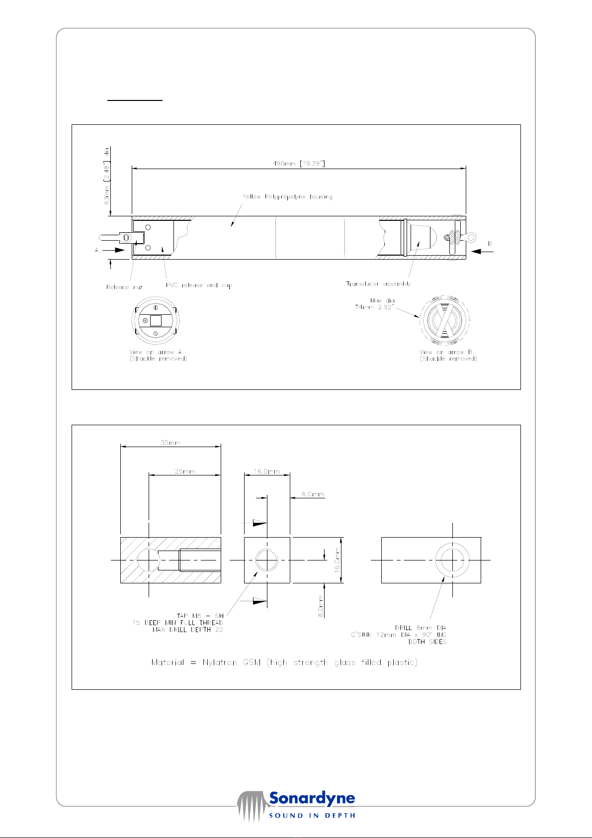
5. DRAWINGS
5.1 LRT Outline Drawing
5.2 Release Nut Manufacturing Drawing
Table of contents
Other Sonardyne Marine Equipment manuals


