JRC Alphatron Marine AlphaTurn User manual

AlphaTurn
Rate of Turn Indicator (MED)
Installation and Operation Manual
www.jrc.am

Contents
I Preface..........................................................................................................4
I.1 Revision History........................................................................................................................................................4
I.2 Glossary.................................................................................................................................................................... 4
I.2.1 Definitions.........................................................................................................................................................4
I.2.2 Abbreviations....................................................................................................................................................5
I.3 Norms and Standards...............................................................................................................................................6
II Safety Information......................................................................................7
II.1 Pictorial Indication....................................................................................................................................................7
II.2 Cautions................................................................................................................................................................... 7
II.3 Notices......................................................................................................................................................................7
II.4 Warranty...................................................................................................................................................................8
II.5 Storage.....................................................................................................................................................................8
III Introduction................................................................................................9
1 Installation Instructions...........................................................................10
1.1 Mechanical Installation...........................................................................................................................................10
1.1.1 Supplied Parts...............................................................................................................................................10
1.1.2 Dimensions....................................................................................................................................................10
1.1.3 Mounting Instrument......................................................................................................................................10
1.1.4 Fitting Instrument Mounting Frame...............................................................................................................11
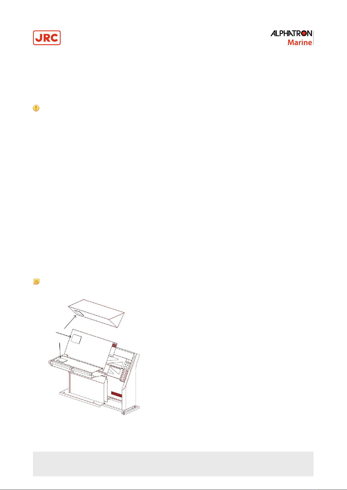
1.1.5 Fitting Instrument Water Seal.......................................................................................................................11
1.1.6 Instrument Electric Connections................................................................................................................... 12
1.1.7 Cable.............................................................................................................................................................12
1.1.8 Cable Preparation......................................................................................................................................... 13
1.1.8.1 Cable Preparation Sending Sides........................................................................................................13
1.1.8.2 Cable Preparation Receiving Sides.....................................................................................................14
1.1.9 Grounding Instrument....................................................................................................................................14
1.1.10 Instrument Power Supply............................................................................................................................14
1.1.11 Serial Interfaces.......................................................................................................................................... 15
1.1.12 Serial Connection........................................................................................................................................16
1.1.13 Relay........................................................................................................................................................... 17
1.1.14 Connecting Serial Ports..............................................................................................................................18
1.1.15 Connecting Dimmer.....................................................................................................................................19
1.2 Software Installation...............................................................................................................................................20
1.2.1 Selecting Active Software.............................................................................................................................20
1.2.1.1 Software Applications...........................................................................................................................20
1.2.2 Software Updates..........................................................................................................................................21
1.2.3 Watchdog Protection.....................................................................................................................................21
2 Operation...................................................................................................22
2.1 Power..................................................................................................................................................................... 22
2.2 Main Screen...........................................................................................................................................................22
2.3 Menu Handling.......................................................................................................................................................24
2.3.1 Default Values AlphaLine Instrument........................................................................................................... 25
2.4 Indication Handling.................................................................................................................................................26
2 | Contents

2.5 Settings...................................................................................................................................................................30
2.5.1 Generic Settings............................................................................................................................................30
2.5.1.1 Generic Settings Menu........................................................................................................................ 30
2.5.1.2 Touch Screen Calibration (TOUCH CAL)............................................................................................31
2.5.1.3 Cleaning Display ( CLEAN MODE )....................................................................................................32
2.5.1.4 Change Theme (THEME).................................................................................................................... 33
2.5.1.5 Change Date and Time (DATE/TIME).................................................................................................34
2.5.1.6 About the AlphaLine instrument (ABOUT)...........................................................................................35
2.5.1.7 ROT Settings (ROT SET)....................................................................................................................36
2.5.2 Advanced Settings........................................................................................................................................ 37
2.5.2.1 Advanced Settings Menu (ADV SET)..................................................................................................37
2.5.2.2 Central Dimming (CNTRL DIM)...........................................................................................................38
2.5.2.3 Ethernet Configuration (ETH CONFIG)............................................................................................... 39
2.5.2.4 Serial Port Configuration (UART CONFIG)......................................................................................... 40
2.5.2.5 Serial Port Monitor (SERIAL MON).....................................................................................................41
2.5.2.6 Factory Reset (RESET).......................................................................................................................42
2.5.2.7 Log (LOG)............................................................................................................................................ 43
2.5.2.8 NMEA Talker (NMEA TALKER)...........................................................................................................44
2.5.2.9 NMEA Settings ( NMEA SET )............................................................................................................45
3 Maintenance..............................................................................................46
4 Appendix A................................................................................................47
4.1 Hardware Specifications.........................................................................................................................................48
4.1.1 Specifications MFM.......................................................................................................................................48
4.1.2 Available Accessories................................................................................................................................... 48
4.2 Software Specifications..........................................................................................................................................49
4.2.1 Supported NMEA Sentences IEC 61162......................................................................................................49
4.2.2 Indication List................................................................................................................................................ 49
4.3 Mechanical Drawings.............................................................................................................................................50
4.3.1 Mechanical Drawing MFM............................................................................................................................ 50
4.4 Electric Diagrams...................................................................................................................................................51
4.4.1 Cable Diagram AlphaTurn............................................................................................................................ 52
4.4.2 Connection Diagram AlphaTurn....................................................................................................................53
4.5 Schematics.............................................................................................................................................................54
4.5.1 Schematics AlphaLine MF Display Unit........................................................................................................55
4.5.2 Schematics AlphaLine Instrument.................................................................................................................56
3 | Contents

I Preface
The Alphatron Marine AlphaLine instrument range was designed for navigation and control of ships and is based on
generic hardware and software, allowing for many different applications.
• Thoroughly read this instruction manual before installation and operation of the equipment.
• We recommend to keep this manual nearby the equipment to ensure ready access to it.
I.1 Revision History
Revision No. Software Version Description Date
V1.0.6 R1_035 First issue 16 December 2016
V1.0.7 R1_050 Textual changes 27 September 2017
V1.0.8 R1_061 Textual changes 09 October 2017
I.2 Glossary
The glossary contains a list of definitions and a list of abbreviations.
I.2.1 Definitions
The meaning of standard definitions as used in this manual are explained in Table 1: Definitions on page 4.
Redundant A device that is equipped with multiple part of the same type, for example a double
power supply. This equipment will continue to function when one of the redundant part
fails.
Heading users Navigation equipment that uses heading/course information for functioning.
Hardware The physical parts of the AlphaLine instrument.
LEDs Light-emitting diodes. These are used for signaling statuses of hardware and software
signals to the user.
Central alarm system /
Bridge watch monitoring System that is connected to all vital systems on a ship and that is able to give a
centralized indication of the (alarm)status of all connected systems.
NMEA protocol Protocol standard for transmitting and receiving of asynchronous serial data sentences.
Talker Device which transmits data. This is usually called transmitter or TX.
Listener Device which receives data. This is usually called receiver or RX.
ISO GND Isolated Ground. This is a ground connection to be used for reference signal. It is
different from EARTH and should normally not be connected to EARTH.
Grounding point/stud Point on the chassis of the AlphaLine instrument which should be connected to the ship's
mass.
Printed Circuit Board A printed circuit board, or PCB, is used to mechanically support and electrically connect
electronic components using conductive pathways, or traces, etched from copper sheets,
laminated onto a non-conductive substrate.
(Galvanic) isolated Electrical separation of two circuits. There is no current flowing directly from one circuit
to another. Electrical energy and/or information can still be exchanged between the
sections by other means, such as by induction or by optical means (like transformers or
opto couplers).
CAN bus Controller Area Network. This is a network based serial bus system used for exchanging
information. It is the advanced version of RS485/422 serial buses.
4 | Preface

Reverse polarity protection This is a part of the power supply hardware that prevents any damage to the equipment
when the power supply is connected to the wrong polarity.
ROT signal Rate Of Turn (ROT) signal indicates the course change of a ship in degrees per minute.
This signal can be analog using voltage or current, or can be an NMEA data signal.
Heading/bearing repeaters Navigation type of instruments displaying the heading/course of a ship.
Baud rate This is the transmission speed of serial interfaces in characters per second.
Transmitting interval The frequency at which complete NMEA sentences are being transmitted in number of
times per second.
Factory setting Instrument setting for backlight color, language, number of connected apparatus, etc. as
configured as a new instrument by the factory.
Flash memory Non-volatile type of memory. This type of memory retains its contents even when the
instrument is turned off.
Firmware (Embedded) software inside the processors of the AlphaLine instrument.
Compass safe distance The minimum distances to equipment that will not cause an unacceptable deviation of
the ship's standard and steering compasses.
Table 1: Definitions
I.2.2 Abbreviations
Abbreviations as used in this manual are explained in Table 2: Abbreviations on page 5.
A Ampere
ARD AlphaLine Repeater Display
CAN Controller Area Network
DC Direct Current
DP Dynamic Position
ECDIS Electronic Chart Display Information System
GPS Global Positioning System
I/O Inputs and Outputs
I.S. Inter Switch
LED Light-Emitting Diode
mA Milliampere
mm Millimeter
NC Normally Closed
NMEA National Marine Electronics Association
NO Normally Open
OA Operational Alarm
TAP Type Approval Program
PCB Printed Circuit Board
RCU Remote Control Unit
5 | Preface
Table of contents
Other JRC Marine Equipment manuals

JRC
JRC JFC-130 - User manual

JRC
JRC JFV-130HP Series User manual

JRC
JRC jue-87 User manual

JRC
JRC Alphatron Marine Mode Switch 3 Pos User manual

JRC
JRC JAN-7201 User manual

JRC
JRC Alphatron AlphaPilot MFS User manual

JRC
JRC Alphatron Marine AlphaAnnounce User manual

JRC
JRC JQE-103 - User manual

JRC
JRC JHS-770S - User manual

JRC
JRC JFE-680 - User manual

JRC
JRC NDC-2000 User manual

JRC
JRC JHS-180 User manual

JRC
JRC JFE-582 User manual

JRC
JRC JHS-182 - User manual

JRC
JRC JAN-7201S User manual

JRC
JRC AlphaWind AlphaLine Series User manual

JRC
JRC ALPHATRON Marine AlphaRiverTrackPilot User manual

JRC
JRC JHS-180 User manual

JRC
JRC JFC-180BB User manual

JRC
JRC Alphatron AlphaPilot FU Tiller User manual