CMT ORANGE TOOLS CMT300 User manual

Instruction Manual
Manual de instrucciones
Manuel d‘instruction
Manuale di istruzioni
Gebrauchsanweisungen
Instrukcja obsługi
Инструкция
EN p. 4
ES p. 20
FR p. 36
IT p. 52
DE S. 68
PL S. 84
RU S.100
CMT300
UNIVERSAL JOINTING SYSTEM
Sistema universal de empalme para encajes
Système universel pour assemblages à encastrement
Sistema di giunzioni universale per incastri
Universelle Bohrhilfe für Verbindungen
Uniwersalny system do wykonywania połączeń
Универсальная соединительная система


C.M.T. Utensili S.p.A.
Via della Meccanica
61122 Pesaro, Fraz. Chiusa di Ginestreto
Italia
tel_+39 0721 48571
fax_+39 0721 481021
e-mail_info@cmtorangetools.com
web site_www.cmtorangetools.com
CMT USA, inc.
7609 Bentley Road Suite D
Greensboro, NC 27409 USA
Phone 336-854-0201
Fax 336-854-0903
e-mail_info@cmtorangetools.com

AA
4
www.cmtorangetools.com
INDEX page
1) Contents of the package 4
2) Assembling the CMT300 5
3) Installing the router 7
4) Using the CMT300 and standard CMT300-T128 template 7
5) Optional CMT300-T064 template 9
6) Optional CMT300-T080 template 11 - 13 - 14
7) Optional CMT300-T127 template 12 - 13 - 14
8) Optional CMT300-T129 template 15 - 17 - 18 - 19
9) Optional CMT300-T190 template 16 - 17 - 18 - 19
10) Conclusions 19
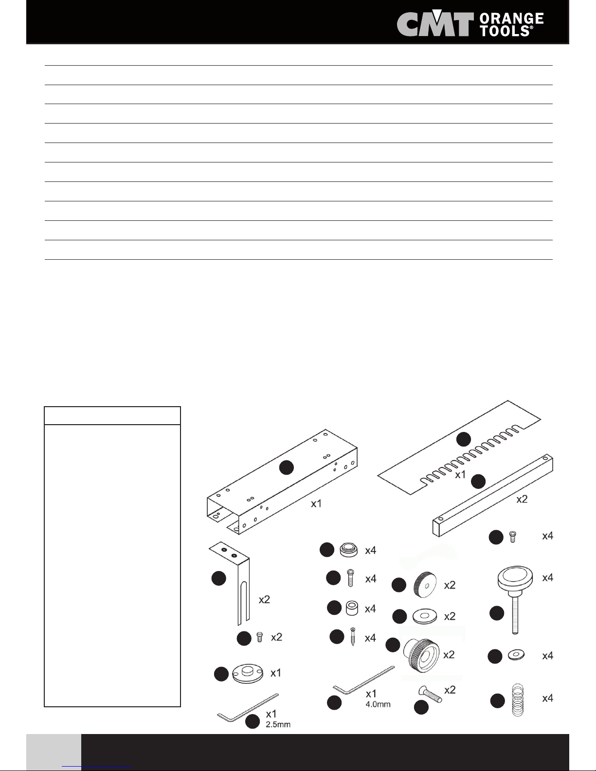
INDEX AND CONTENTS OF THE PACKAGE
Thanking you for having purchased our products, we wish you many hours of enjoyable work with thems!
Whether you are a professional or not, our universal assembly system will enable you to make any type
of joint easily and rapidly.
This system can be adapted to any type of router, thanks to its special universal sub-base in transparent
PETG (supplied separately).
1. Contents of the package
When you open the package, you will find the following parts inside:
No. Order No. Q.ty
11 CMT300-01 1
12 CMT300-02 2
13 CMT300-03 4
14 CMT300-04 2
15 CMT300-T128 1
16 CMT300-06 4
17 CMT300-07 4
18 CMT300-08 4
19 CMT300-09 4
10 CMT300-10 4
11 CMT300-11 2
12 CMT300-12 2
13 CMT300-13 2
14 CMT300-14 4
15 CMT300-15 2
16 CMT300-16 4
18 CMT300-18 2
19 899.005.00 1
20 991.062.00 1
21 991.064.00 1
1
10
11
12
13
14
15
16
18
19
20
21
2
3
4
5
6
7
8
9
AA
5
www.cmtorangetools.com
Fig.3
Template
ASSEMBLING THE CMT300
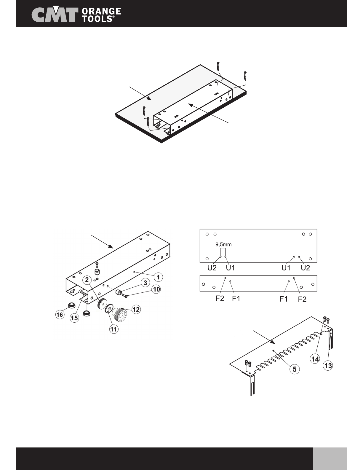
2) Assembling the CMT300
Fig. 1: The first job is to mount the CMT300 on the workbench. Four self-tapping screws are supplied for
this purpose.
Fig. 2: This diagram enables to understand how to mount the components required to adjust the position
of the template. First of all, fit screw 15 in the hole of the body, using the hex key (supplied) and carefully
tightening it, fitting lock nut 2 on the other side, then fit washer 11 and tighten nut 12 manually. Repeat this
procedure on the other side of the body.
The components (3) and screws (10) are used to position the wood. Tighten the stops (3) on the body (1)
using the screws (10). Set the stops in the positions U1 on the top of the system and F1 on the front of the
system.
Fig. 3: : This diagram enables to mount the template 5.
Fit the two adjustable supports (13) on it with the four screws (14).
Fig. 4: This diagram shows how to install the clamping bars that will enable the workpiece to be held in place.
These bars have a sandpaper coating, which ensures more grip and therefore a better hold on the workpiece
during machining.
Fit the two screws with over-sized locking knobs (7) in the washers (8), in the bar (4) and in the spring (9).
Workbench
Unit
Workbench
Fig.1
Fig.2 Overhead view
Front view

AA
6
www.cmtorangetools.com
All that has to be done now is to tighten the two screws with the over-sized locking knobs in the threaded
holes.
Repeat this procedure for the front bar.
Fig. 5: Lastly, place the template on the body of the CMT300.
To do so, just fit the supports (13) between parts 2 and 11.
Fig. 6: Once the template is positioned, it can be adjusted on the two axes - X and Y. Just tighten or loosen
the stop nut (2) for X-axis settings and raise or lower the guides (13) for Y-axis settings. Once the exact
setting has been found, tighten nut 12 to lock in place. Assembly is now complete.
ASSEMBLING THE CMT300
CMT300
CMT300
As
s
e X
Asse Y
Fig.4
Fig.5
Fig.6
Adjusting the template
AA
7
www.cmtorangetools.com
INSTALLING THE ROUTER
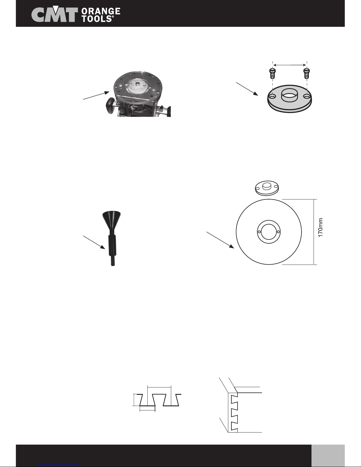
3) Installing the router
To use the CMT300 system, a router is required, on which a guide ring must be fitted, to enable the machine
to be controlled on the template.
be impossible to install the guide ring on the router being used (due to the dimensions), a universal sub-base
(supplied separately) is available.
This sub-base has an external diameter of 170mm and is supplied with a line-up/centering pin to enable it
to be correctly fitted to the router.
Optional universal sub-base supplied separately
CMT300-SB1 (for Ø8 and Ø12mm shanks)
CMT300-SB2 (for Ø6.35 and Ø12.7mm shanks)
Once the guide is installed on the router, a CMT dovetail bit can be fitted for machining the wood.
4) Using the CMT300 with a standard CMT300-T128 template
The CMT300 system is supplied with a standard template (CMT300-T128), with which 12.7mm half-blind
dovetail joints can be machined using a normal CMT dovetail bit (purchased separately).
Bits that can be used with the standard CMT300-T128 template:
718.127.11 (Ø6mm shank)
818.128.11 (Ø6.35mm shank)
918.127.11 (Ø8mm shank)
Ø
50mm
Guide ring
(50mm wheelbase)
Router
Line-up
centering pin
Universal sub-base
(for guide ring)
Half-blind dovetail joint
(CMT300-T128)
21.5mm
9.5mm
(3/8”)
12.7mm
(1/2”)
AA
8
www.cmtorangetools.com
USING THE CMT300 WITH A STANDARD
CMT300-T128 TEMPLATE
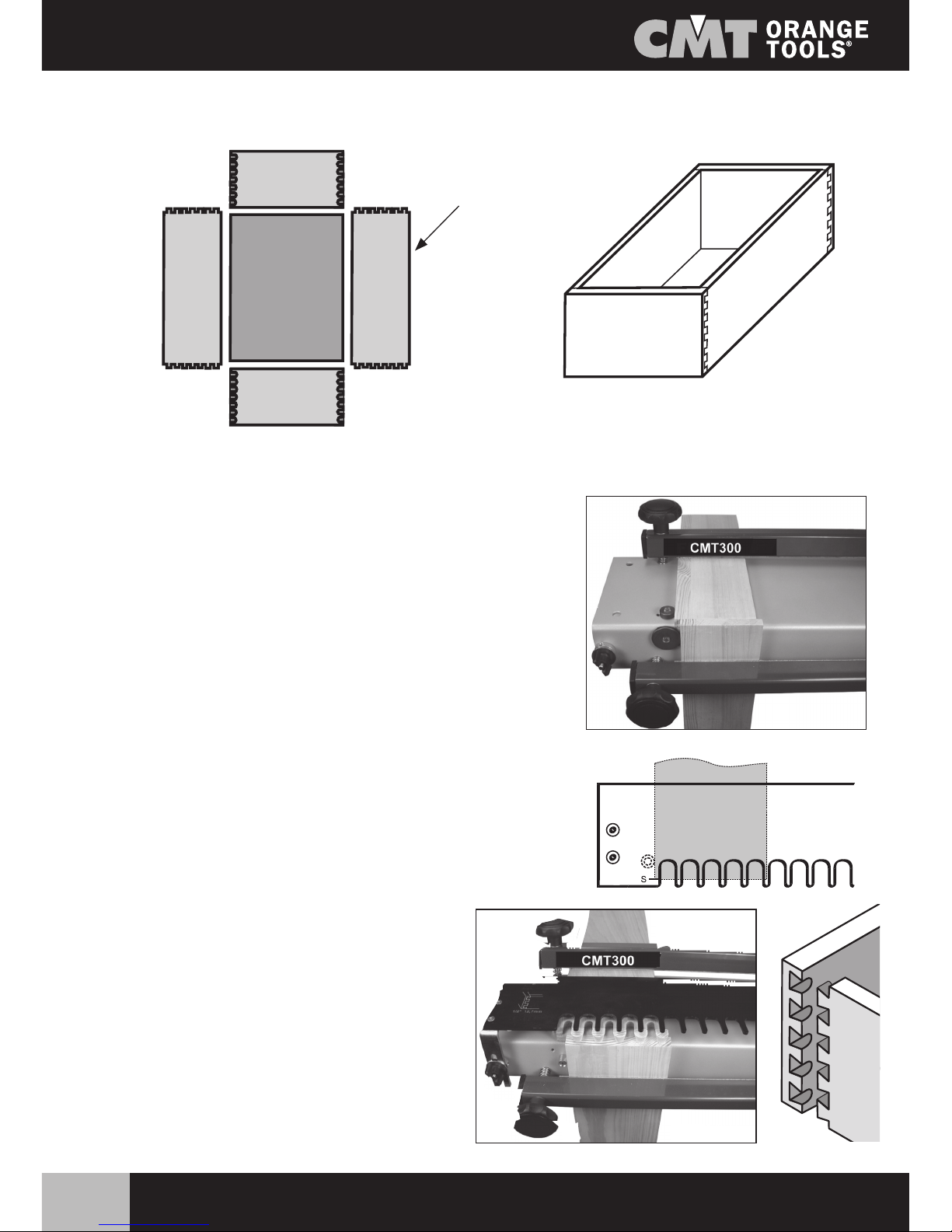
Example of making a drawer with a standard CMT300-T128 template:
Y4 Y3
Y1 Y2
X4
X1
X3
X2
X3
X4
Y3
X2
X1
Y4
Y1 Y2
With each pass of the router on the board edge, a complete
assembly is machined (X1 con Y1, X2 with Y2...), so to make a
complete drawer, four work cycles must be carried out.
Positioning the wood parts and machining:
1) Place the wood part (X1, X2....) vertically against the small
positioning buffer and clamp it sufficiently with the bar to ensure
it does not slip.
2) Place the wood part (Y1, Y2....) horizontally against the small
positioning buffer and clamp it sufficiently with the bar to ensure
it does not slip.
3) Level the two pieces of wood.
4) Tighten the clamping bar of the vertical part completely.
5) Tighten the clamping bar of the horizontal part completely.
6) Position the template and tighten the nuts that hold it in place.
Dismantled
drawer
Right-hand
side
Left-hand
side
Rear
Front
7) Move up to and away from the workpiece from
the front - not from above - to avoid the risk of
missing the guide and ruining the joint.
8) Position the router and follow the profile of the
template to carry out the machining.
9)The first assembly is finished - repeat the previous
procedure as often as required.
AA
9
www.cmtorangetools.com
OPTIONAL CMT300-T064 TEMPLATE
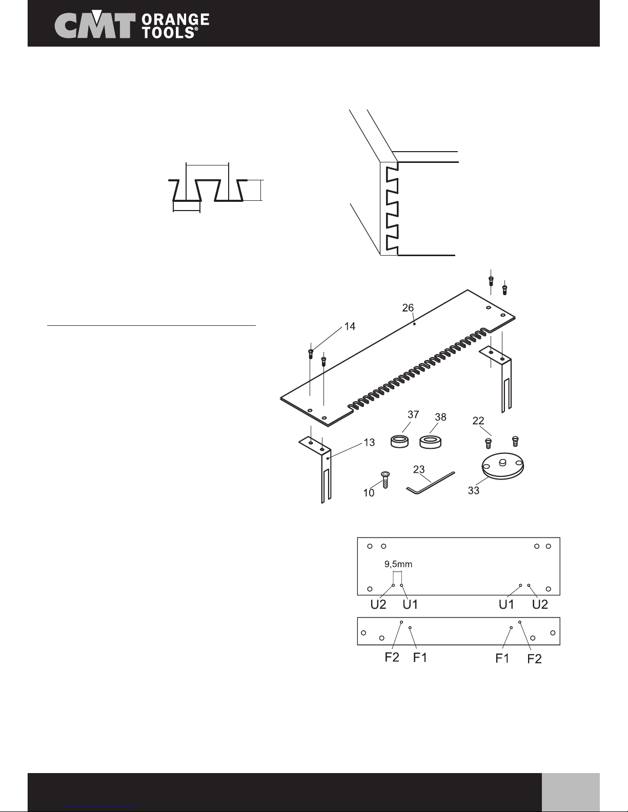
5) Optional CMT300-T064 template
The CMT300-T064 template can be purchased as an optional and enables to make mini half-blind
dovetail joints.
Contents of the CMT300-T064 package:
26) CMT300-T064 template
14) Four M4x8mm screws
37) Two Ø15.8x6mm stop rings
38) Two Ø28.6x4mm stop rings
10) Four M4x16mm screws
33) Ø7.8x4mm guide ring
22) Two M5x8mm screws
23) 2.5mm hex key
Mounting the template: this template is mounted in the
same way as the standard model.
Remove the standard template from the CMT300 system
and replace it with the 26 template, fixing it on the
supports (13 - included in the CMT300 package), using
the screws (14).The stop rings (37 and 38) replace those
supplied as standard.
The 38 rings, which have a larger diameter than the 37
ones, are mounted on the front in F2, whereas the other
37 rings are mounted on the top part, in U1.
Fitting the guide ring: to use this template, it is necessary to dismantle the guide ring already on the
router, and replace it with the other ring (33). Then mount a dovetail bit (718.060.11 with Ø6mm shank or
818.064.11 with Ø6.35mm shank) to carry out the machining.
from
CMT300
from
CMT300
CMT300-T064
11.3mm
6mm
6.35mm
(1/4”)
Overhead view
Front view
Mini half-blind
dovetail joints
(CMT300-T064)

AA
10
www.cmtorangetools.com
OPTIONAL CMT300-T064 TEMPLATE
Example of making a drawer with a standard CMT300-T064 template:
Dismantled
drawer
Right-hand
side
Left-hand
side
Rear
Front
Y4 Y3
Y1 Y2
X4
X1
X3
X2
X3
X4
Y3
X2
X1
Y4
Y1 Y2
With each pass of the router, a complete assembly is machined on
the workpiece (X1 with Y1, X2 with Y2...), so to make a complete
drawer, four work cycles must be carried out.
Positioning the wood parts and machining:
1) Place the wood part (X1, X2....) vertically against the small
positioning buffer and clamp it sufficiently with the bar to ensure
it does not slip.
2) Place the wood part (Y1, Y2....) horizontally against the small
positioning buffer and clamp it sufficiently with the bar to ensure
it does not slip.
3) Level the two pieces of wood.
4) Tighten the clamping bar of the vertical part completely.
5) Tighten the clamping bar of the horizontal part completely.
6) Position the template and tighten the nuts to hold it in place.
7) Move up to and away from the workpiece from
the front - not from above - to avoid the risk of
missing the guide and ruining the joint.
8) Position the router and follow the profile of the
template to carry out the machining.
9) The first assembly is finished - repeat the
previous procedure as often as required.
AA
11
www.cmtorangetools.com
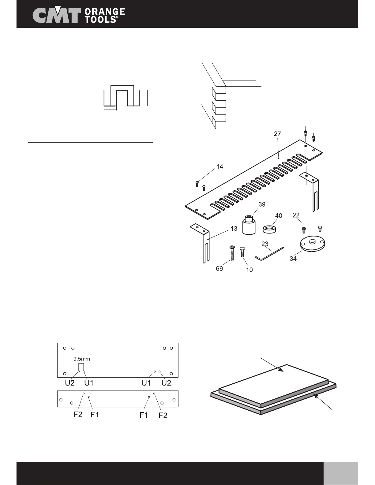
OPTIONAL CMT300-T080 TEMPLATE
6) Optional CMT300-T080 template
The CMT300-T080 template can be purchased as an optional and enables to make mini box joints.
Contents of the CMT300-T080 package:
27) CMT300-T080 template
14) Four M5x8mm screws
39) Two Ø15x7/Ø21x18 stop rings
69) Two M4x35mm screws
40) Two Ø14x6mm stop rings
10) Two M4x16mm screws
34) Ø11.1x4 guide ring
22) Two M5x8mm screws
23) 2.5mm hex key
Mounting the template: this template is mounted in the same way as the standard model. Remove the
standard template from the CMT300 system and replace it with the other template (27), fixing it on the
supports (13 - included in the CMT300 package), using the screws (14).The stop rings (39 and 40) replace
those supplied as standard. The two rings 39 are mounted on the front in F2, whereas the others (40) are
fitted on the front in F1 and are only used for machining a particular structure, as can be seen in Fig.7. In this
case, the upper part of the wood is up against ring 40 and the lower part up against ring 39.
Fitting the guide ring: replace the guide ring already on the router with ring 33. Then mount a straight bit
(881.081.11 with Ø6.35mm shank or 912.080.11 with Ø8mm shank), which will carry out the machining.
Mini box joints
(CMT300-T080)
from
CMT300
from
CMT300
CMT300-T080
Overhead view
Front view
Upper part
Fig.7
Lower part
16mm
(5/8”)
8mm
(5/16”)
20/30mm

AA
12
www.cmtorangetools.com
OPTIONAL CMT300-T127 TEMPLATE
Overhead view Upper part
Fig.7
Lower part
7) Optional CMT300-T127 template
The CMT300-T127 template can be purchased as an optional and enables to make box joints.
Contents of the CMT300-T127 package:
29) CMT300-T127 template
14) Four M4x8mm screws
43) Two Ø7.8x7/Ø17.2x24 stop rings
69) Two M4x40mm screws
44) Two Ø19.65x6mm stop rings
10) Two M4x16mm screws
23) 2.5mm hex key
Mounting the template: this template is mounted in the same way as the standard model. Remove the
standard template from the CMT300 system and replace it with template 29, fixing it on the supports (13 -
included in the CMT300 package), using the screws (14).The stop rings (43 and 44) replace those supplied
as standard. The two (longer) rings (43) are mounted on the front in F2, whereas the others (44) are fitted
on the front in F1 and only used for machining a particular structure, as can be seen in Fig.7. In this case,
the upper part of the wood is up against ring 44 and the lower part up against ring 43.
Box joints
(CMT300-T127)
from
CMT300
from
CMT300
from
CMT300
CMT300-T127
Front view
25.4mm
(1”)
30/35mm
12.7m
m
(1/2”)
Fitting the guide ring: to use this template, it is necessary to mount the Ø15.8x4mm guide ring (35)
already on the CMT300. Then mount a CMT straight bit (812.127.11 with Ø6.35mm shank, 912.127.11
with Ø8mm shank or 812.627.11 with Ø12.7mm shank), which will carry out the machining.

AA
13
www.cmtorangetools.com
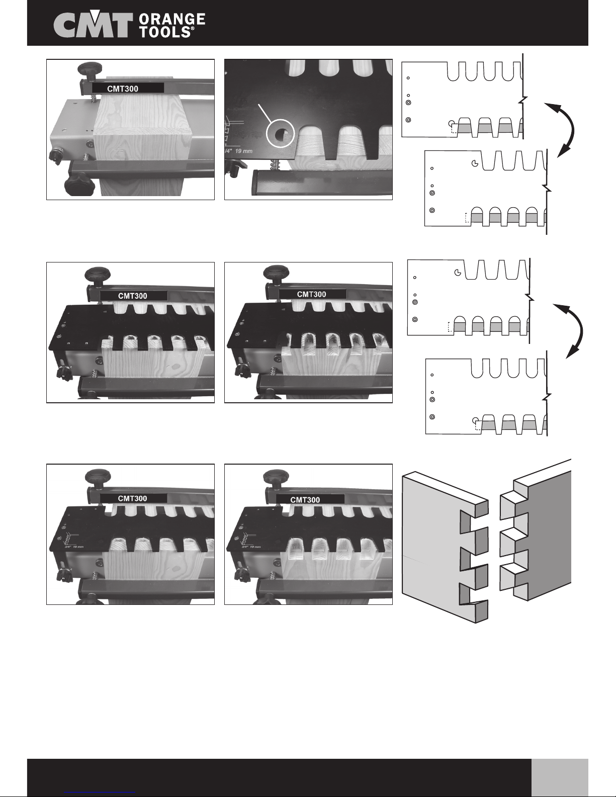
OPTIONAL CMT300-T080 AND CMT300-T127 TEMPLATE
Example of making a drawer with CMT300-T080 and CMT300-T127 template:
X3
X4
Y3
Y2
Y4
Y1
X2
X1
Dismantled
drawer
Right-hand
side
Left-hand
side
Rear
Front
With each machining run, an assembly is made (X1, X2..., Y1
Y2), so, to make a complete drawer, eight machining cycles
have to be carried out.
With these two templates, two types of joints can be made, as
can be seen in the following illustrations.
For the machining, a piece of scrap stock 5mm thicker than the piece to be machines must be placed
horizontally. This piece of wood used horizontally is only used to support the vertical part to be machined.
Scrap stock
Wood to be
machined
X1
X2
X4
X3
Y1 Y4
Y2 Y3

AA
14
www.cmtorangetools.com
OPTIONAL CMT300-T080 AND CMT300-T127 TEMPLATE
Positioning the wood parts and machining:
1) Place the wood part (X1..., Y2....) vertically against the small positioning buffer and clamp it sufficiently
with the bar to ensure it does do not slip.
2) Place the piece of scrap stock horizontally and push it against the vertical piece.
3) Match the ends of the two pieces of wood.
4) Tighten the clamping bar of the vertical part completely.
5) Tighten the clamping bar of the horizontal part completely.
6) Position the template and tighten the nuts to hold it in place.
7) Move up to and away from the workpiece from the front - not from above - to avoid the risk of missing
the guide and ruining the joint.
8) Position the router and follow the profile of the template to carry out the machining.
9) The first assembly is finished - repeat the previous procedure as often as required.

AA
15
www.cmtorangetools.com
OPTIONAL CMT300-T129 TEMPLATE
8) Optional CMT300-T129 template
The CMT300-T129 template can be purchased as an optional and enables to make 12.7x20mm open
dovetail joints.
Contents of the CMT300-T129 package:
31) CMT300-T129 template
14) Four M4x8mm screws
44) Two Ø21.85x6mm stop rings
14) Two M4x16mm screws
34) Ø11.1x4mm guide ring
22) Two M5x8mm screws
23) 2.5mm hex key
Mounting the template: this new template is mounted in
the same way as the standard model. Remove the standard
template from the CMT300 system and replace it with
template 31, fixing it on the supports (13 - included in the
CMT300 package), using the screws (14). The stop rings
(45) replace those supplied as standard and are mounted
on the front in F2.
Mounting the guide ring: it can be seen that this template has two sides, as the joint is made using two
bits: one for each side of the template. On the first (straight) side, the Ø12.7 dovetail bit (818.129.11 with
Ø6.35mm shank or 918.129.11 with Ø8mm shank) will be used, with the standard Ø15.8x4mm guide ring
(supplied with the CMT300), whereas on the other (dovetail) side, the Ø8mm straight bit (811.081.11 with
Ø6.35mm shank or 912.080.11 with Ø8mm shank) will be used with Ø11.1x4mm ring (34), supplied with
the template.
from
CMT300
from
CMT300
from
CMT300
CMT300-T129
Overhead view
Front view
Open dovetail joints
(CMT300-T129)
20mm
12.7mm
(1/2”)

AA
16
www.cmtorangetools.com
OPTIONAL CMT300-T190 TEMPLATE
9) Optional CMT300-T190 template
The CMT300-T190 template can be purchased as an optional and enables to make 19x22mm open dovetail
joints.
Contents of the CMT-T190 package:
32) CMT300-T190 template
14) Four M4x8mm screws
46) Two Ø16.3x6mm stop rings
10) Two M4x16mm screws
36) Ø22x4mm guide ring
22) Two M5x8mm screws
23) 2.5mm hex key
Open dovetail joints
(CMT300-T190)
from
CMT300
from
CMT300
from
CMT300
CMT300-T190
Assembling the template: this template is mounted in the
same way as the standard model. Remove the standard
template from the CMT300 system and replace it with
template 32, fixing it on the supports (13 - included in the
CMT300 package), using the screws (14). The stop rings
(46) replace those supplied as standard and are mounted
on the front in F2.
Mounting the guide ring: it can be seen that this template has two sides, as the joint is made using two
bits: one for each side of the template. On the first (straight) side, the Ø19mm dovetail bit (718.190.11
Ø6mm shank – 818.190.11 Ø6.35mm shank – 918.190.11 Ø8mm shank – 918.690.11 Ø12mm shank
– 818.690.11 Ø12.7mm shank) will be used, with the Ø22x4mm guide ring (36) supplied with the template,
whereas on the other (dovetail) side, the Ø12.7mm straight bit (812.127.11 Ø6.35mm shank – 912.127.11
Ø8mm shank – 811.627.11 Ø12.7mm shank) will be used with the standard Ø15.8x4mm ring, supplied
with the template.
Overhead view
Front view
20/30m
m
19mm
(3/4”)

AA
17
www.cmtorangetools.com
OPTIONAL CMT300-T129 AND CMT300-T190 TEMPLATE
Example of making a drawer with CMT300-T129 and CMT300-T190 template:
With each completed run, an assembly is made (X1, X2...., Y1 Y2...), so to make a complete drawer, eight
work cycles must be carried out.
Using the two sides:
The first part of the template (with the straight slots) enables to make the X-axis cuts (X1, X2...), using a CMT
dovetail bit and the corresponding guide ring.
The second (dovetail) part of the template enables to make the Y-axis cuts (Y1, Y2...), using a CMT straight
bit and the corresponding guide ring.
X3
X4
Y3
Y2
Y4
Y1
X2
X1
Second side of the template
(to be used with the straight bit)
First side of the template
(to be used with the dovetail bit)
Dismantled
drawer
Right-hand
side
Left-hand
side
Rear
Front

AA
18
www.cmtorangetools.com
Positioning the wood parts and machining:
1) Place the wood part X1 vertically against the small positioning buffer and clamp the bar sufficiently to
ensure it does not slip.
2) Place the scrap stock horizontally and push it against the vertical piece.
3) Match the ends of the two pieces of wood.
4) Tighten the clamping bar of the vertical part completely.
5) Tighten the clamping bar of the horizontal part completely.
6) Place the template on its second (dovetail) side and check in the small hole in the template that the two
pieces are well matched.
7) Turn the template on to the first side (with the straight slots). Make certain to use the correct guide ring
and the CMT dovetail bit.
8) Move up to and away from the workpiece from the front - not from above - to avoid the risk of missing
the guide.
9) Position the router and follow the profile of the template to carry out the machining.
10) The first assembly is finished - repeat the previous procedure to make all X-axis cuts.
11) Remove the template and leave the scrap stock in place.
12) Place the wood part (Y1) vertically against the small positioning buffer and clamp the bar sufficiently to
ensure it does not slip.
13) Match the ends of the two pieces of wood.
14) Tighten the clamping bar of the vertical part completely.
17) Turn the template on to the second (dovetail) side. Make certain to use the correct guide ring and the
CMT straight bit.
16) Move up to and away from the workpiece from the front - not from above - to avoid the risk of missing
the guide.
17) Position the router and follow the profile of the template to carry out the machining.
18) The first assembly is finished - repeat the previous procedure for the rest of the joints to be made.
The following page has some illustrations that help to better understand the stages described above.
For the machining the wood components, a piece of scrap stock necessary for the machining (which will later
be thrown away) that is 5mm thicker than the piece to be machined must be placed horizontally.
This scrap stock is a piece of wood required to hold the vertical part to be machined steady.
OPTIONAL CMT300-T129 AND CMT300-T190 TEMPLATE
Scrap stock
Wood to be
machined
AA
19
www.cmtorangetools.com
OPTIONAL CMT300-T129 AND CMT300-T190 TEMPLATE
10) Conclusions:
You have just assembled and used the CMT300 system. In addition to these instructions, there is the
commercial documentation of the items and relative code numbers of the CMT300 system. In particular,
there are the optional templates, the description of the bits use and the relative code numbers.
We hope you enjoy working with the CMT300 system.
Fig.1 Fig.2
Fig.3
Fig.4 Fig.6
Fig.5
Fig.7
Fig.6
Fig.8
Fig.6
Wood
position
Scrap stock
Work piece
Fig.9
20
www.cmtorangetools.com
1
10
11
12
13
14
15
16
18
19
20
21
2
3
4
5
6
7
8
9
ÍNDICE página
1) Contenido del embalaje 20
2) Montaje del CMT300 21
3) Instalación de la electrofresadora 23
4) Utilización del CMT300 y plantilla estándar CMT300-T128 23
5) Plantilla opcional CMT300-T064 25
6) Plantilla opcional CMT300-T080 27 - 29 - 30
7) Plantilla opcional CMT300-T127 28 - 29 - 30
8) Plantilla opcional CMT300-T129 31 - 33 - 34 - 35
9) Plantilla opcional CMT300-T190 32 - 33 - 34 - 35
10) Conclusiones 35
ÍNDICE Y CONTENIDO DEL EMBALAJE
Le agradecemos la compra de nuestros productos y le deseamos buen trabajo.
Que sea Ud. un profesional o no, con nuestro sistema de empalme universal podrá crear fácil y rápidamente
cualquier tipo de encaje.
Este sistema puede adaptarse a cualquier tipo de electrofresadora gracias a la base universal especial de
PETG transparente (suministrada a parte).
1. Contenido del embalaje
Al abrir el embalaje, encontrará las piezas siguientes:
No. Código Cant.
11 CMT300-01 1
12 CMT300-02 2
13 CMT300-03 4
14 CMT300-04 2
15 CMT300-T128 1
16 CMT300-06 4
17 CMT300-07 4
18 CMT300-08 4
19 CMT300-09 4
10 CMT300-10 4
11 CMT300-11 2
12 CMT300-12 2
13 CMT300-13 2
14 CMT300-14 4
15 CMT300-15 2
16 CMT300-16 4
18 CMT300-18 2
19 899.005.00 1
20 991.062.00 1
21 991.064.00 1
Table of contents
Languages:
Other CMT ORANGE TOOLS Power Tools manuals

CMT ORANGE TOOLS
CMT ORANGE TOOLS POCKET-PRO PPJ-002 User manual

CMT ORANGE TOOLS
CMT ORANGE TOOLS CMT3000 User manual

CMT ORANGE TOOLS
CMT ORANGE TOOLS CMT333 User manual

CMT ORANGE TOOLS
CMT ORANGE TOOLS CMT7E User manual

CMT ORANGE TOOLS
CMT ORANGE TOOLS TW-200 User manual

CMT ORANGE TOOLS
CMT ORANGE TOOLS Industrio Operating instructions


