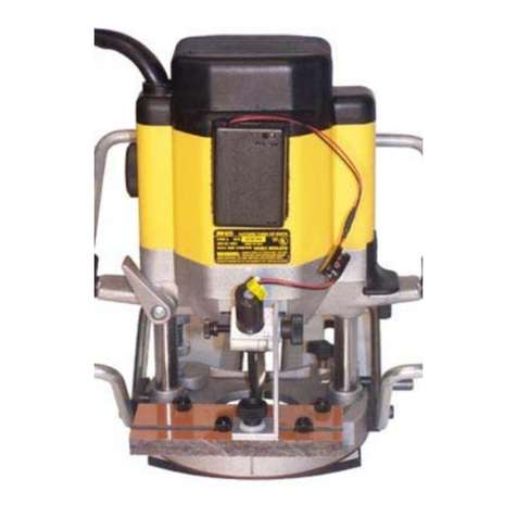
CMT ORANGE TOOLS CMT7E User manual

CMT7E
2400W
Precision Router
EN OPERATING & SAFETY INSTRUCTIONS
NL BEDIENINGS EN VEILIGHEIDSVOORSCHRIFTEN
FR INSTRUCTIONS D’UTILISATION ET CONSIGNES DE SÉCURITÉ
DE SICHERHEITS UND BEDIENUNGSANLEITUNG
IT ISTRUZIONI PER L’USO E LA SICUREZZA
ES INSTRUCCIONES DE USOY DE SEGURIDAD
PT INSTRUÇÕES DE OPERAÇÃO E SEGURANÇA
PL INSTRUKCJA OBSŁUGI I BEZPIECZEŃSTWA
RU
ИНСТРУКЦИИ ПО ЭКСПЛУАТАЦИИ И ПРАВИЛА ТЕХНИКИ БЕЗОПАСНОСТИ
CMT7E
EN - OPERATING & SAFETY INSTRUCTIONS (PAGE 8)
ES - INSTRUCCIONES DE USO Y DE SEGURIDAD (PÁGINA 15)
FR - INSTRUCTIONS D’UTILISATION ET CONSIGNES DE SÉCURITÉ (PAGE 22)
IT - ISTRUZIONI PER L’USO E LA SICUREZZA (PAGINA 29)
DE - SICHERHEITS- UND BEDIENUNGSANLEITUNG (SEITE 36)
PT - INSTRUÇÕES DE OPERAÇÃO E SEGURANÇA (PÁGINA 43)
DA - BETJENINGS OG SIKKERHEDSINSTRUKTIONER (SIDE 50)
PL INSTRUKCJA OBSŁUGI I BEZPIECZEŃSTWA (STRONA 57)
CZ NÁVOD K OBSLUZE A BEZPEČNOSTNÍ POKYNY (STRANA 64)
RU ( 71)
DUAL MODE
UPDATED
VERSION
with
No Voltage Release (NVR)
Safety System
2400W Precision Router
ES Electrofresadora FR Défonceuse IT Elettrofresatrice DE Oberfräse PT Eletrofresadora
DA Overfræser PL Frezarka CZ Horní frézka RU Фрезер

2www.cmtorangetools.com
EN
2www.cmtorangetools.com
EN
8
7
5
2
3
13
20
21
6
4
12
26
28
9
1
11
19
18
17
16
15
24 30
27
23
25
14
10
22
29
Collets
Diameter
ORDER NO.
D = 6mm 796.660.00
D = 6,35mm 796.664.00
D = 8mm 796.680.00
D = 10mm 796.700.00
D = 12mm 796.720.00
D = 12,7mm 796.727.00
Optional (Not Included)
Description
ORDER NO.
Prebored
plastic router plate CMT300-SB
Guide bush Ø30mm 899.007.00
Optional (Not Included)

www.cmtorangetools.com 3
EN
www.cmtorangetools.com 3
EN
Fig. II 18.5
70.618.5
70.6
18.5
33.2
67.2
74.1
44.9
12
18.5
58.2
70.6
38.9
70.6
57.2
106.75
A
BC
Ø180
Ø80
106.75
103.25
103.25
115
Ø
Fig. I

4www.cmtorangetools.com
EN
4www.cmtorangetools.com
EN
A B
EF
C D

www.cmtorangetools.com 5
EN
www.cmtorangetools.com 5
EN
K L
JI
G H

6www.cmtorangetools.com
EN
6www.cmtorangetools.com
EN
O P
Q
M N
R

www.cmtorangetools.com 7
EN
www.cmtorangetools.com 7
EN
ST
U

8www.cmtorangetools.com
EN
8www.cmtorangetools.com
EN
Wear hearing protection
Wear eye protection
Wear breathing protection
Wear head protection
Wear hand protection
WARNING – To reduce the risk of injury, user must read instruction manual
Caution
Warning: Sharp blades or teeth!
DO NOT use in rain or damp environments!
Always disconnect from the power supply when adjusting, changing accessories,
cleaning, carrying out maintenance and when not in use!
Dust extraction required or recommended
Class II construction (double insulated for additional protection)
Environmental Protection. Waste electrical products should not be disposed of with
household waste. Please recycle where facilities exist. Check with your local authority
or retailer for recycling advice.
Conforms to relevant legislation and safety standards.
Specication
Model no: CMT7E
Voltage: 220 - 240V~ 50/60Hz
Max input current: 9.1A
Max output power: 2400W
No-load speed: 8000 - 21,000min-1
Collet: 8mm & 12mm
Maximum cutter diameter (Free Plunge): 55mm (2-3/16")
Maximum collet size: ½” (12.7mm)
Height adjustment: 1) Free Plunge
2) Table Height Winder
3) Micro Adjuster (Fine Adjustment)
Plunge Range: 0-68mm
Ingress protection: IPX0
Protection class:
Power cord length: 3m
Dimensions (L x W x H): 180 x 300 x 310mm
Weight: 6.5 kg
As part of our ongoing product development, specications of CMT products may alter
without notice
Sound and vibration information:
Sound pressure LPA:84.2dB(A)
Sound power LWA:95.2dB(A)
Uncertainty K: 3dB(A)
Weighted Vibration ah:5.4m/s²
Uncertainty K: 1.5m/s²
Original Instructions
Description of Symbols
The rating plate on your tool may show symbols. These represent important information about
the product or instructions on its use.
Thank you for purchasing this CMT product.This manual contains information neces- sary
for safe and effective operation of this product. This product has unique features and,
even if you are familiar with similar products, it is necessary to read this manual carefully
to ensure you fully understand the instructions. Ensure all users of
the product read and fully understand this manual. Keep these instructions with the
product for future reference.
Introduction Technical Abbreviations Key
VVolts
~Alternating current
AAmpere
Hz Hertz
W, kW Watt, kilowatt
min-1 Revolutions per minute

www.cmtorangetools.com 9
EN
www.cmtorangetools.com 9
EN
The sound intensity level for the operator may exceed 85dB(A) and sound protection measures
are necessary.
WARNING: Always wear ear protection where the sound level exceeds 85dB(A) and limit
the time of exposure if necessary. If sound levels are uncomfortable, even with ear protection,
stop using the tool immediately and check the ear protection is correctly tted and provides the
correct level of sound attenuation for the level of sound produced by your tool.
WARNING: User exposure to tool vibration can result in loss of sense of touch,
numbness,tingling and reduced ability to grip. Long term exposure can lead to a chronic
condition. If necessary, limit the length of time exposed to vibration and use anti-vibration
gloves. Do not operate the tool with hands below a normal comfortable temperature, as
vibration will have a greater effect. Use the gures provided in the specication relating to
vibration to calculate the duration and frequency of operating the tool.
WARNING: The vibration emission during actual use of the power tool can differ from
the declared total value depending on the ways in which the tool is used. There is the need to
identify safety measures to protect the operator that are based on an estimation of exposure in
the actual conditions of use (taking account of all parts of the operating cycle such as the times
when the tool is switched off and when it is running idle in addition to the trigger time).
The declared vibration total value has been measured in accordance with a standard test
method and may be used for comparing one tool with another. The declared vibration tota value
may also be used in a preliminary assessment of exposure.
Sound levels in the specication are determined according to international standards. The
gures represent normal use for the tool in normal working conditions. A poorly maintained,
incorrectly assembled, or misused tool, may produce increased levels of noise and vibration.
www.osha.europa.eu provides information on sound and vibration levels in the workplace that
may be useful to domestic users who use tools for long periods of time.
General Power Tool Safety Warnings
WARNING: Read all safety warnings, instructions, illustrations and specications
provided with this power tool. Failure to follow all instructions listed below may result in
electric shock, re and/or serious injury.
Save all warnings and instructions for future reference.
The term “power tool” in the warnings refers to your mains-operated (corded) power tool or
battery-operated (cordless) power tool.
1) Work area safety
a) Keep work area clean and well lit. Cluttered or dark areas invite accidents.
b) Do not operate power tools in explosive atmospheres, such as in the presence of
ammable liquids, gases or dust. Power tools create sparks which may ignite the dust or
fumes.
c) Keep children and bystanders away while operating a power tool. Distractions can cause
you to lose control.
2) Electrical safety
a) Power tool plugs must match the outlet. Never modify the plug in any way. Do not use
any adapter plugs with earthed (grounded) power tools. Unmodied plugs and matching
outlets will reduce risk of electric shock.
b) Avoid body contact with earthed or grounded surfaces, such as pipes, radiators, ranges
and refrigerators. There is an increased risk of electric shock if your body is earthed or
grounded.
c) Do not expose power tools to rain or wet conditions. Water entering a power tool will
increase the risk of electric shock.
d) Do not abuse the cord. Never use the cord for carrying, pulling or unplugging the
power tool. Keep cord away from heat, oil, sharp edges or moving parts. Damaged or
entangled cords increase the risk of electric shock.
e) When operating a power tool outdoors, use an extension cord suitable for outdoor use.
Use of a cord suitable for outdoor use reduces the risk of electric shock.
f) If operating a power tool in a damp location is unavoidable, use a residual current
device (RCD) protected supply. Use of an RCD reduces the risk of electric shock.
g) When used in Australia or New Zealand, it is recommended that this tool is ALWAYS
supplied via Residual Current Device (RCD) with a rated residual current of 30mA or
less.
h) Use proper extension cord. Make sure your extension cord is in good condition. When
using an extension cord, be sure to use one heavy enough to carry the current your
product will draw. An undersized cord will cause a drop in line voltage resulting in loss of
power and overheating.
3) Personal safety
a) Stay alert, watch what you are doing and use common sense when operating a power
tool. Do not use a power tool while you are tired or under the inuence of drugs,
alcohol or medication. A moment of inattention while operating power tools may result in
serious personal injury.
b) Use personal protective equipment. Always wear eye protection. Protective equipment
such as a dust mask, non-skid safety shoes, hard hat or hearing protection used for
appropriate conditions will reduce personal injuries.
c) Prevent unintentional starting. Ensure the switch is in the OFF-position before
connecting to power source and/or battery pack, picking up or carrying the tool.
Carrying power tools with your nger on the switch or energising power tools that have the
switch ON invites accidents.
d) Remove any adjusting key or wrench before turning the power tool ON. A wrench or a
key left attached to a rotating part of the power tool may result in personal injury.
e) Do not overreach. Keep proper footing and balance at all times. This enables better
control of the power tool in unexpected situations.
f) Dress properly. Do not wear loose clothing or jewellery. Keep your hair and clothing
away from moving parts. Loose clothes, jewellery or long hair can be caught in moving
parts.
g) If devices are provided for the connection of dust extraction and collection facilities,
ensure these are connected and properly used. Use of dust collection can reduce dust-
related hazards.
h) Do not let familiarity gained from frequent use of tools allow you to become
complacent and ignore tool safety principles. A careless action can cause severe injury
within a fraction of a second.
4) Power tool use and care
a) Do not force the power tool. Use the correct power tool for your application. The correct
power tool will do the job better and safer at the rate for which it was designed.
b) Do not use the power tool if the switch does not turn it ON and OFF. Any power tool that
cannot be controlled with the switch is dangerous and must be repaired.
c) Disconnect the plug from the power source and/or remove the battery pack,
if detachable, from the power tool before making any adjustments, changing
accessories, or storing power tools. Such preventive safety measures reduce the risk of
starting the power tool accidentally.
d) Store idle power tools out of the reach of children and do not allow persons unfamiliar
with the power tool or these instructions to operate the power tool. Power tools are
dangerous in the hands of untrained users.
e) Maintain power tools and accessories. Check for misalignment or binding of moving
parts, breakage of parts and any other condition that may affect the power tool’s
operation. If damaged, have the power tool repaired before use. Many accidents are
caused by poorly maintained power tools.
f) Keep cutting tools sharp and clean. Properly maintained cutting tools with sharp cutting
edges are less likely to bind and are easier to control.
g) Use the power tool, accessories and tool bits, etc. in accordance with these
instructions, taking into account the working conditions and the work to be performed.
Use of the power tool for operations different from those intended could result in a
hazardous situation.
h) Keep handles and grasping surfaces dry, clean and free from oil and grease. Slippery
handles and grasping surfaces do not allow for safe handling and control of the tool in
unexpected situations.
5) Service
a) Have your power tool serviced by a qualied repair person using only identical
replacement parts. This will ensure that the safety of the power tool is maintained.

10 www.cmtorangetools.com
EN
10 www.cmtorangetools.com
EN
Additional Safety for Routers
WARNING!
• Hold the power tool by insulated gripping surfaces only, because the cutter may
contact its own cord. Cutting a “live” wire may make exposed metal parts of the power
tool “live” and could give the operator an electric shock.
• Use clamps or another practical way to secure and support the workpiece to a stable
platform. Holding the work by your hand or against the body leaves it unstable and may
lead to loss of control.
• If the replacement of the supply cord is necessary, this has to be done by the
manufacturer or his agent in order to avoid a safety hazard.
• It is strongly recommended that the tool always be supplied via a residual current
device with a rated residual current of 30 mA or less.
a) Use safety equipment including safety goggles or shield, ear protection, dust mask and
protective clothing including safety gloves
b) Cloths, cord, string etc should never be left around the work area
c) Ensure the mains supply voltage is the same as the tool rating plate voltage
d) Ensure any cable extensions used with this tool are in a safe electrical condition, and
have the correct ampere rating for the tool
e) Completely unwind cable drum extensions to avoid potential overheating
f) Use appropriate detectors to determine if utility cables or pipes are below the surface
of the work area. Consult utility companies for assistance if necessary. Contact with
electric cables can lead to electric shock and re. Damaging a gas pipe can lead to
explosion. Contact with water lines can lead to major property damage
g) Ensure embedded objects such as nails and screws have been removed from the
workpiece before commencing operation
h) Handle router bits with care as they can be extremely sharp
i) Before use, check the bit carefully for signs of damage or cracks. Replace damaged or
cracked bits immediately
j) Ensure router cutters/bits are sharp and maintained correctly. Dull cutting edges can
lead to uncontrolled situations including stalling, increased heat and possible injury
k) ALWAYS use both handles and maintain a rm grip on the router before proceeding
with any work
l) Keep handles and gripping surfaces dry, clean and free of oil and grease to ensure the
tool can be securely held in use
m) Before using the tool to make a cut, switch on and let it run for a while. Vibration could
indicate an improperly installed bit
n) Take notice of the direction of rotation of the bit and the direction of feed
o) Keep your hands away from the routing area and router bit cutter. Hold the auxiliary
handle or an insulated gripping surface with your second hand
p) NEVER start the router while the cutter is touching the workpiece
q) Ensure the plunge spring is always tted when using hand-held
r) Ensure the cutter has completely stopped before plunging to the collet lock position
s) The maximum speed of the router bit/cutter must be at least as high as the maximum
speed of the power tool
t) Parts of the router bits may become hot during operation. Do not handle immediately
after use to avoid risk of burns
u) Do not allow parts to come into contact with combustible materials
v) The shank size of the router cutter/bit must be matched to the exact same size collet
tted to the router. Incorrectly tted router cutter/bits will rotate irregularly and have
increased vibration that could lead to loss of control
w) DO NOT press the spindle lock button, or attempt to switch the tool into bit change
mode while the router is operating
x) Keep pressure constant while cutting into the workpiece, allowing the router bit cutter
to dictate the speed of cut. DO NOT force the tool and overload the motor
y) Ensure rating labels and safety warnings on the tool remain clear to read and are replaced
if marked or damaged
z) When operating the router, be prepared for the router bit cutter stalling in the
workpiece and causing loss of control. Always ensure the router is rmly held and the
on/off switch is immediately released in such circumstances
• After switching on the router, check the router bit is rotating evenly (not ‘wobbling’)
and there is no additional vibration due to the router bit being incorrectly tted.
Operating the router with an incorrectly tted router bit can lead to loss of control and
severe injury
• EXTREME care must be taken when using cutters with a diameter greater 50mm (2”).
Use very slow feed rates and/or multiple shallow cuts to avoid overloading the motor
• ALWAYS switch off and wait until the bit has come to a complete standstill before
removing the machine from the workpiece
• Disconnect from the power supply before carrying out any adjustment, servicing or
maintenance
• Even when this tool is used as prescribed it is not possible to eliminate all residual
risk factors. If you are in any doubt as to safe use of this tool, do not use it
WARNING: Dust generated by using power tools can be toxic.Some materials may be
chemically treated or coated and be a toxic hazard. Some natural and composite materials
may contain toxic chemicals. Some older paints may contain lead and other chemicals.Avoid
prolonged exposure to dust generated from operating a router. DO NOT allow dust to get onto
skin or eyes and do not allow the dust to enter your mouth to prevent absorption of harmful
chemicals. Where possible, work in a well-ventilated area. Use a suitable dust mask and dust
extraction system where possible. Where there is a higher frequency of exposure, it is more
critical that all safety precautions are followed and a higher level of personal
protection is used.
Product Familiarisation
1. Turret Stops
2. Chuck
3. Depth Stop
4. Side Air Vents
5. Depth Stop Lock Knob
6. Motor
7. Retracting Power Switch Cover
8. On/Off Power Switch
9. Brush Access Covers
10. Speed Controller
11. Plunge Lock Lever
12. Safety Guards
13. Baseplate Mounting Knobs
14. Table Height Winder Connection Point
15. Dust Extraction Port
16. Automatic Spindle Lock
17. Winder Handle Clutch Ring
18. Plunge Selection Button
19. Winder Handle
20. Micro Winder
21. Plunge Spring Access Cap
22. NVR Bypass Key Connection
23. Fence
24. Collet (x 2)
25. Table Height Winder
26. Spanner
27. Circle Cutting Pivot Mount
28. Extended Baseplate
29. Bypass Key
30. Scews (1/4 UNC x 4) for fastening on CMT table (spare part 990.467.00)
Fig. II
A. ¼ UNC x4
B. M6 x3
C. Table Winder Indent

www.cmtorangetools.com 11
EN
www.cmtorangetools.com 11
EN
Intended Use
Hand-held precision plunge router. Used for cutting proles, grooves, edges and elongated holes
in natural and composite wood.Also used with guide bushes and templates for cutting shapes,
following patterns, as well as for stationary installation in compatible router table systems.
The tool must ONLY be used for its intended purpose.Any use other than those
mentioned in this manual will be considered a case of misuse. The operator,
and not the manufacturer, shall be liable for any damage or injury resulting from
such cases of misuse. The manufacturer shall not be liable for any modications
made to the tool, nor for any damage resulting from such modications.
Unpacking Your Tool
• Carefully unpack and inspect your new plunge router. Familiarise
yourself with all its features and functions
• Ensure that all parts of the tool are present and in good condition. If any parts are
missing or damaged, have such parts replaced before attempting to use this tool
Before Use
WARNING: Ensure the tool is disconnected from the power supply before
attaching or changing any accessories, or making any adjustments.
WARNING: Periodically, during prolonged use or when the router has been
transported or dropped, check the Plunge Spring Access Cap (21) is correctly located
and secured in place. It should sit parallel with the body of the tool with no visible
gap, and the securing screw should be correctly located to prevent the Plunge Spring
Access Cap from accidently unscrewing, see Image O.The plunge spring is tensioned
with sufcient force to cause serious injury if released in an uncontrolled manor. Always
follow the instructions carefully when removing and replacing the plunge spring.
Collet & cutter installation
Note: Wear protective gloves when inserting and removing
router bits due to the sharp edges of the cutters.
1. Place the router upside down on a secure at surface, with the motor
completely stationary and the power cable removed from the mains
2. Plunge the router to its maximum depth by pressing the Winder Handle
Clutch Ring (17) (Image B) inwards, and turning the Winder Handle
(19) clockwise until the Collet (24) is protruding the base
Note: Ensure the Depth Stop (3) is fully retracted (see ‘Depth stop and turret’). The
Collet should be protruding through the base, allowing easy spanner access
3. Using the Spanner (26) provided, loosen the Collet by turning it anti-clockwise
until removal
4. Select the desired Collet, and install into the Chuck (2) by screwing the Collet in clockwise
5. Insert the router cutter into the Collet ensuring that at least 20mm or 3/4
of the shaft (whichever is greater) is inserted into the Collet, then use the
Spanner to turn the Collet slightly, allowing the collet lock to engage (Image
C). Once engaged, turn the spanner clockwise to tighten the cutter
6. Return the router to a normal operating depth. This will disengage the collet lock and
release the retracting switch shutter, enabling access to the On/Off Power Switch (8)
Dust extraction port
Note: The CMT7E Router is equipped with a Dust Extraction Port (15) for chip extraction above
the cut. The Dust Extraction Port accepts hoses measuring 38mm (1 “) with lefthand threading
(anti-clockwise) (Image D).
Extended baseplate & fence installation
1. Locate the two Baseplate Mounting Knobs (13) and loosen them completely. This permits
the mounting studs to engage the router securing holes on the Extended Baseplate (28)
2. Turn both the plunge router and the Extended Baseplate upside down
3. Press the Baseplate Mounting Knobs on the plunge router inwards, to expose the mounting
studs
4. Align the mounting studs with the router securing holes on the Extended Baseplate, and
slide into the keyhole slots (Image K)
Note: The orientation of the Extended Baseplate depends on where the support is required. For
edge work, locate the On/Off Power Switch (8) on the short overhang side of the base
5. Tighten the Baseplate Mounting Knobs on the plunge router rmly to secure the plunge
router to the Extended Baseplate
6. To t the Fence (23) loosen the fence knobs, and slide the Fence along the tracks on the
Extended Baseplate (Image L). Lock at the required setting by tightening both fence knobs
Note: When routing trenches at distance from an edge, t the Fence to the long end of the
Extended Baseplate.
Note: When performing edge work with a non-bearing guided cutter, t the Fence to the short
end of the baseplate (Image J).
Note: If using a very large diameter cutter it may be necessary to x wooden blocks to the fence
faces via the screw holes, to ensure the cutter does not contact the Fence.
Operation
WARNING: ALWAYS wear eye protection, adequate respiratory and hearing
protection, as well as suitable gloves, when working with this tool.
Switching ON & OFF
Note: When the router is connected to the power source, the On/Off
Power Switch (8) will illuminate in both ‘On’ and ‘Off’ positions.
Note: The Retracting Power Switch Cover (7) prevents accidental starting of the
router. It must be retracted before the router can be switched on. The Retracting
Power Switch Cover will remain open until the router is switched off.
1. Ensure that the plunge router is at the maximum extension of its travel, and that
the cutter will not conict with any foreign objects when it is powered on
2. Connect the power cord to the mains, and slide the Retracting Power
Switch Cover back to reveal the On/Off Power Switch
3. Press the On/Off Power Switch in the ‘I’ position to turn the plunge router ON.
Whilst the On/Off Power Switch is in this position, the Retracting Power Switch
Cover will be prevented from re-covering the On/Off Power Switch
4. To turn OFF, press the On/Off Power Switch in the ‘O’ position.The
Retracting Power Switch Cover will slide back to its original position
Variable speed control
Note: Generally, the highest speed that does not cause burn marks on the workpiece should
be used. Where stated, always follow the cutter manufacturers’ maximum speed limitations.
• Operating at reduced speed increases the risk of damage to the router as a
result of overload. Use very slow feed rates and/or multiple shallow cuts
• The Speed Controller (10) is marked 1 to 5, corresponding approximately with the
speeds and cutter diameters below. Turn the dial to select the required speed
Setting RPM Cutter Diameter
5 21,000 Up to 25mm (1")
4 18,000 25-50mm (1"- 2")
3 14,500 50-65mm (2"- 21⁄2")
2 11,000 Over 65mm (21⁄2")
1 8000 Use only if burning

12 www.cmtorangetools.com
EN
12 www.cmtorangetools.com
EN
Cutting depth adjustment
IMPORTANT:
YOU WILL DAMAGE YOUR PLUNGE MECHANISM IF YOU
DO NOT FOLLOW THESE INSTRUCTIONS.
ALWAYS ensure the Plunge lock lever (11) is unlocked by setting it to its highest
position before adjusting the cutting depth using the ‘Free plunge’ or ‘Winder handle
adjustment’ methods below.
Note: To lock the router at a particular depth of cut, plunge the router head down and rotate
the Plunge Lock Lever (11) to its lower position. This will hold the router head in this position.
• There are three methods of cut depth adjustment, depending on the accuracy and
control required:
Free plunge
1. Free plunge depth adjustments can be made with the Plunge Selection Button (18)
engaged. Press the Plunge Selection Button deep inside the handle until it engages inward
(Image A)
2. Release the Plunge Lock Lever (11) and push the body of the router until the required
depth is reached. Re-lock the Plunge Lock Lever
Winder handle adjustment
1. Plunge depth adjustments can be made by turning the Winder Handle (19)
2. Disengage the Plunge Selection Button (18), and ensure the button is ush with the Winder
Handle (Image K)
3. To release the Winder Handle, pull the Winder Handle Clutch Ring (17) inwards (Image B)
4. Release the Plunge Lock Lever (11) and twist the Winder Handle until the desired depth
of cut is reached. Release the Winder Handle Clutch Ring, and lock the Plunge Lock Lever
Micro Winder
Note: For use in Winder Handle (19) plunge mode only.
1. Disengage the Plunge Selection Button (18), and ensure that the Plunge Lock Lever (11) is
unlocked
Note: If the Micro Winder (20) is turned with the Plunge Lock Lever engaged, the Micro Winder
will start clicking and the cut depth will remain unchanged.
2. Turn the Micro Winder clockwise to increase cut depth and anti-clockwise to reduce cut
depth. Adjust the cut depth until the desired height is reached
Note: When the end of the depth adjustment range is reached, the Micro Winder will offer
greater resistance and will begin to ‘click’.
3. Engage the Plunge Lock Lever, particularly for heavy cuts
Depth stop & turret
1. The Depth Stop (3) and Turret Stops (1) are used to accurately pre-set up to three different
cut depths
2. Loosen the Depth Stop Lock Knob (5) and retract the Depth Stop fully, then re-tighten
(Image F)
3. Set the turret posts to the required plunge depths using the scales on the stationary turret
post (Image G)
Note: To change turret posts, rotate the entire turret assembly to align with the Depth Stop.
4. With the desired cutter installed into the Collet (24), adjust the plunge depth until the tip of
the cutter touches the workpiece
5. Rotate the turret until the xed turret post is in line with the Depth Stop. Release the stop,
allowing it to spring on to the post, then re-tighten the Depth Stop Lock Knob. The plunge
depth is now set at zero
6. Rotate the Turret Stops until the turret post with the desired plunge depth is aligned with
the Depth Stop
Making a cut
Note: NEVER operate the router freehand without some form of guide. Guidance can be
provided by a bearing guided router bit cutter, the supplied guides, or a straight edge (Image I).
1. ALWAYS hold the router using both hands, on the handles provided. Ensure that the
workpiece will not move. Use clamps wherever possible
2. Allow the motor to reach its full operating speed
3. Lower the router bit cutter into the workpiece whilst moving the router slowly, keeping the
baseplate held at against the workpiece
4. If edge cutting, the cutting of the workpiece should be on the left side relative to the cutting
direction, (Fig I). Keep the pressure constant and allow the cutter to work
steadily through the material. Be aware that knots, and other variations, will slow
the rate of progress
Note: To avoid ‘bit chatter’, direct the cut anti-clockwise for external cuts, and clockwise for
internal cuts.
Note: Moving the router too fast can result in a poor quality nish, and overloading of the motor.
Moving the router too slowly can result in overheating the workpiece.
Note: Normal operation of a router is to plunge the head after the router has been switched on.
Note: Do not operate the router upside down unless securely mounted in a well-guarded router
table (e.g. CMT brand).
Making multiple pass cuts
1. The Turret Stops (1) allow the maximum depth of cut to be achieved in an operator-
determined number of steps. Each step of the turret can be pre-set by adjusting the
thumbwheel on the turret post
2. Rotate the Turret Stops so that the Depth Stop (3) will contact the highest pre-set turret
post when the router is plunged. The rst pass of the cut can now be made
3. Continue to make passes, rotating the Turret Stops and adjusting the turret post depth for
each pass when necessary until the full depth of cut has been achieved
Circle Cutting
1. Fit the Extended Baseplate (28), without the Fence (23) attachment, to the router
2. Remove the Circle Cutting Pivot Mount (27) from the Extended Baseplate and x it to the
centre of the workpiece, using a small nail or screw, through one of the holes in the pivot
mount, (Image M). Leave the pivot mount bolt in position
3. Lower the router and base over the pivot mount and ret the washer and wing-nut,
(Image N)
4. With the power switched ‘Off’, rotate the router along the intended path to check the circle,
and make any necessary adjustments
5. Cut the circle in several passes, lowering the cut depth by approximately 2mm (3/32”)
each pass, (Image N). Do not attempt to cut deeply in one pass
• Through cuts: If cutting all the way through the material, x a sacricial board to the
underneath of the workpiece.

www.cmtorangetools.com 13
EN
www.cmtorangetools.com 13
EN
Table-mounted operation
Note: Fitting and operating this router on a router table should be carried
out in accordance with the literature supplied with the router table.
Note: Whilst this product was designed for efcient and convenient operation on most router
tables, it is particularly suited for use with CMT Router Tables.
Note: Router adjustments are extremely easy using the unique features described earlier
in the manual. See ‘Collet and cutter installation’ and ‘Cutting depth adjustment’.
IMPORTANT: The plunge spring MUST be removed before this router is tted into a router table:
1. Set the router at the top of its plunge range and engage the Plunge Lock Lever (11)
2. Loosen the small screw next to the Plunge Spring Access Cap (21) a few turns (Image O)
3. Using the palm of your hand, apply downward pressure on the Plunge Spring Access Cap
and grip the Plunge Spring Access Cap rmly with your other hand to prevent the plunge
spring from shooting upwards when released.Whilst maintaining the downward pressure
and a rm grip, twist the Plunge Spring Access Cap anti-clockwise to remove it (Image P)
WARNING: The plunge spring is tensioned with great force to enable a smooth
plunging action. The Plunge Spring Access Cap and plunge spring will shoot up quickly
with the same force once it has been unscrewed. Be careful not to release the Plunge
Spring Access Cap in an uncontrolled manor, which could cause personal injury.
4. Slowly allow the Plunge Spring Access Cap to raise upwards once released (Image Q)
5. Remove the spring and store in a safe place
6. Replace the Plunge Spring Access Cap and re-tighten the screw
WARNING: When re-inserting the plunge spring, carefully check that the Plunge
Spring Access Cap is correctly fastened. It should sit parallel with the body of
the tool with no visible gap, and the securing screw should be correctly located
to prevent the Plunge Spring Access Cap from accidently unscrewing.
NOTE: Be sure to re-t the plunge spring before using the router freehand.
IMPORTANT: Before mounting the router under the router table, make sure the Depth Stop
Lock Knob (5) is loosened and the Plunge Lock Lever (11) is in the unlocked position.
• The Table Height Winder (25) engages with the Table Height Winder Connection Point (14)
for quick and easy above-the-table height adjustment when the router is table-mounted
Installing the No Voltage Release bypass key:
The CMT7E router has a No Voltage Release (NVR) function which prevents the motor from
automatically restarting after a power interruption. To reset the tool, the switch must be returned
to the OFF position before switching back ON.When used with CMT tables or those of another
brand, which have their own NVR protection, such as the Electrical Safety Device (999.100.11),
this function can be bypassed by inserting the NVR Bypass Key (29).Thereby enabling the ON/
OFF operation of the tool to be controlled by the ON/OFF switch on the router table.
1. Screw the NVR Bypass Key into the NVR Bypass Key Connection (22) and gently hand
tighten (image T)
2. Secure the bracket to the underside of the work centre (Image U)
3. Switch the router ON and use the router table ON/OFF switch to control the router
WARNING: ONLY use the NVR Bypass Key when the router is connected to a power source
that is itself protected by a No Voltage Release protection system, such as the Electrical Safety
Device (999.100.11).ALWAYS ensure the bracket is connected to the router table to avoid
accidentally removing the router without removing the Bypass Key.
Important
1. To mount the CMT router onto CMT Tables or those of another brand or a table of your
own construction, remove the 4 screws of the black baseplate indicated in Image S and
remove it.
2. There are 2 sets of screw threads as shown in g. II.
• A: There are 4 x UNC screw threads (used to secure the baseplate) which are also suitable
for mounting CMT tables.
• B: set of 3 x M6 threads.
3. Use the 4 screws included (30) to install the router to CMT tables.
Note: The M6 threads are not available on earlier versions of the CMT7E (2022) router.
Accessories
A wide range of suitable accessories and spare parts for this tool are available from your CMT
dealer, such as:
• A large selection of cutter/router bits.
• Prebored router plates (image H) for CMT accesories
• Guide Bushes
• Collets
• Carbon brushes
Maintenance
WARNING: ALWAYS disconnect from the power supply before carrying out any inspection,
maintenance or cleaning.
General Inspection
• Regularly check that all the xing screws are tight
• Inspect the supply cord of the tool, prior to each use, for damage or wear. Repairs should
be carried out by an authorised CMT service centre. This advice also applies to extension
cords used with this tool
Cleaning
WARNING: ALWAYS wear protective equipment including eye protection and gloves when
cleaning this tool.
• Keep your tool clean at all times. Dirt and dust will cause internal parts to wear quickly, and
shorten the device’s service life
• Clean the body of your machine with a soft brush, or dry cloth
• Never use caustic agents to clean plastic parts. If dry cleaning is not sufcient, a mild
detergent on a damp cloth is recommended
• Water must never come into contact with the tool
• Ensure the tool is thoroughly dry before using it
• If available, use clean, dry, compressed air to blow through the ventilation holes
(where applicable)
Lubrication
• Slightly lubricate all moving parts at regular intervals with a suitable spray lubricant
Brushes
• Over time the carbon brushes inside the Motor (6) may become worn
• Excessively worn brushes may cause loss of power, intermittent failure, or visible sparking
• To replace the brushes, remove the two Brush Access Covers (9). Carefully remove the worn
brushes (Image R) and ensure the sockets are clean. Carefully replace with new brushes
and then replace the Brush Access Covers
• After tting run the router without load for 2-3 minutes to help the brushes bed in. The
process of the brushes fully bedding in may take repeated uses. Motor sparking may
continue until new carbon brushes have bedded in
• Alternatively, have the machine serviced at an authorised service centre
Contact
For all technical/repairs service, please contact your dealer.
Web: www.cmtorangetools.com
Storage
• Store this tool carefully in a secure, dry place out of the reach of children
Disposal
Always adhere to national regulations when disposing of power tools
that are no longer functional and are not viable for repair.
• Do not dispose of power tools, or other waste electrical and electronic equipment (WEEE),
with household waste
• Contact your local waste disposal authority for information on the correct way to dispose
of power tools

14 www.cmtorangetools.com
EN
14 www.cmtorangetools.com
EN
Problem Possible cause Solution
No function when On/Off Power Switch
(8) is operated
No power Check power supply
Defective On/Off Power Switch Replace the On/Off Power Switch at an authorised CMT service centre
Inaccurate cutting prole
Depth Stop (3) not correctly adjusted Ensure that the Depth Stop corresponds to the maximum amount of cut permitted by the Turret
Stops (1)
Incorrectly tted or loose router bit/Collet (24) Tighten router bit/Collet and cutter assembly
Router will not operate
No supply of power Check that power is available at source
Brushes worn or sticking Disconnect power, open Brush Access Covers (9) and ensure brushes are not damaged or heavily
worn
Switch is faulty
Have the tool serviced by an authorised CMT service centre
Motor components faulty or short circuited
Router runs or cuts slowly
Blunt or damaged cutter Re-sharpen or replace cutter
Speed Controller (10) set low Increase variable speed setting
Motor is overloaded Reduce pushing force on router
Excessive vibration
Incorrectly tted or loose router bit Ret or tighten router bit
Bent or damaged router bit Replace router bit
Heavy sparking occurs inside motor
housing
Brushes not moving freely Disconnect power, remove brushes, clean or replace
Damaged or worn motor Have the tool serviced by an authorised CMT service centre
Micro Winder (20) “clicks” or not
adjusting
Plunge Lock Lever (11) engaged Release Plunge Lock Lever
Reached end of adjustment range Reset the Micro Winder and set depth with the Depth Stop (3)
Makes an unusual sound Mechanical obstruction Have the tool serviced by an authorised CMT service centre
Damage to internal windings
Troubleshooting

www.cmtorangetools.com 15
EN
www.cmtorangetools.com 15
ES
Características técnicas
Lleve protección auditiva
Lleve protección ocular
Lleve protección respiratoria
Lleve un casco de seguridad
Lleve guantes de seguridad
ADVERTENCIA - Para reducir el riesgo de lesiones, el usuario debe leer y
comprender completamente el manual de instrucciones.
¡Peligro!
¡Atención! Cuchillas/dientes muy alados
NO utilizar en ambientes húmedos o bajo la lluvia
Desconecte siempre la herramienta de la toma eléctrica antes de realizar
cualquier tarea de mantenimiento, sustituir accesorios o cuando no la esté
utilizando.
Se recomienda/necesita utilizar un dispositivo de extracción de polvo
Protección clase II (doble aislamiento para mayor protección)
Protección medioambiental
Los productos eléctricos usados no se deben mezclar con la basura
convencional. Por favor, recicle el producto en las instalaciones
correspondientes. Solicite información a su ayuntamiento o distribuidor sobre
las opciones de reciclaje.
Conforme a las normas de seguridad y la legislación correspondiente.
Traducción del manual original
Modelo: CMT7E
Tensión: 220 – 240 V~, 50/60Hz
Tensión máxima de entrada: 9,1 A
Potencia máxima de salida: 2400 W (3,25 CV pico)
Velocidad sin carga: 8.000 – 21.000 min-1
Pinza de apriete: 8 y 12 mm
Diámetro máximo de la fresa: 55 mm (2-3/16”)
Tamaño máximo de la fresa
(Ajuste libre):
½” (AUS: 12,7 mm)
Ajuste de altura: 1) Ajuste libre
2) Ajustador en la empuñadura
3) Microajustador
Ajuste de profundidad: 0 – 68 mm
Grado de protección: IPX0
Clase de protección:
Longitud del cable de
alimentación:
3 m
Dimensiones (L x An x A): 180 x 300 x 310 mm
Peso: 6,5 kg
Como parte de nuestra política de desarrollo de productos, los datos técnicos de los
productos CMT pueden cambiar sin previo aviso.
Información sobre ruido y vibración:
Presión acústica LPa:84,2 dB(A)
Potencia acústica LWa:95,2 dB(A)
Incertidumbre K: 3 dB(A)
Vibración ponderada ah:5,4 m/s²
Incertidumbre K: 1,5 m/s²
Descripción de los símbolos
Los siguientes símbolos pueden aparecer en la placa de características de su herramienta.
Estos símbolos representan información importante sobre el producto o instrucciones relativas
a su uso.
Introducción
Gracias por haber elegido esta herramienta CMT. Estas instrucciones contienen la información
necesaria para utilizar este producto de forma segura y ecaz. Lea atentamente este manual
para obtener todas las ventajas y características únicas de su nueva herramienta. Conserve
este manual a mano y asegúrese de que todas las personas que utilicen esta herramienta lo
hayan leído y entendido correctamente. Guarde estas instrucciones con el producto para poder
consultarlas en el futuro.
Abreviaturas de términos técnicos
VVoltio/s
~, CA Corriente alterna
AAmperio/s
Hz Hercio/s
W, kW Vatio/s, kilovatio/s
min-1 (revoluciones/oscilaciones) por minuto

16 www.cmtorangetools.com
EN
16 www.cmtorangetools.com
ES
El nivel de intensidad sonora para el usuario puede exceder de 85 dB(A). Se recomienda usar
medidas de protección sonora.
ADVERTENCIA: Utilice siempre protección auditiva cuando el nivel de ruido exceda
exceda 85 dB(A) o cuando esté expuesto durante largos periodos de tiempo. Si por algún
motivo nota algún tipo de molestia auditiva incluso llevando orejeras de protección, detenga
inmediatamente la herramienta y compruebe que las orejeras de protección estén colocadas
adecuadamente.
ADVERTENCIA: La exposición a la vibración durante la utilización de una herramienta
puede provocar pérdida del sentido del tacto, entumecimiento, hormigueo y disminución de
la capacidad de sujeción. La exposición durante largos periodos de tiempo puede provocar
enfermedad crónica. Si es necesario, limite el tiempo de exposición a la vibración y utilice
guantes anti-vibración. No utilice la herramienta cuando sus manos estén muy frías, las
vibraciones tendrán un mayor efecto. Utilice los datos técnicos de su herramienta para evaluar
la exposición y medición de los niveles de ruido y vibración.
ADVERTENCIA: Las vibraciones producidas durante el uso de esta herramienta pueden
ser diferentes al valor total declarado y pueden variar dependiendo del tipo de método de
uso de esta herramienta. Por lo tanto, será necesario aplicar todas las medidas de seguridad
apropiadas para proteger al usuario durante el uso de esta herramienta. Habrá que tener en
cuenta todos los aspectos relacionados con el ciclo de trabajo (apagado de la herramienta,
funcionamiento sin carga y tiempo de accionamiento).
El nivel total de vibraciones producidas ha sido medido mediante un proceso estándar y podrá
evaluarse tomando como referencia los datos de emisión comparativos de máquinas similares.
El nivel de vibración total también podrá utilizarse en una evaluación de exposición previa.
Los niveles de vibración y ruido están determinados según las directivas internacionales
vigentes. Los datos técnicos se reeren al uso normal de la herramienta en condiciones
normales. Una herramienta defectuosa, mal montada o desgastada puede incrementar los
niveles de ruido y vibración. Para más información sobre ruido y vibración, puede visitar la
página web www.osha.europa.eu
Instrucciones de seguridad para
herramientas eléctricas
ADVERTENCIA: Lea siempre cuidadosamente todas las advertencias e instrucciones
de seguridad para utilizar este producto de forma segura. No seguir estas instrucciones
podría causar una descarga eléctrica, incendio y/o lesiones graves.
Conserve estas instrucciones para futuras referencias.
El término “herramienta eléctrica” descrito en este manual se reere a una herramienta
alimentada por conexión eléctrica mediante cable (herramienta alámbrica) o una herramienta
eléctrica alimentada por batería (herramienta inalámbrica).
1) Seguridad en el área de trabajo
a) Mantenga el área de trabajo limpia y bien iluminada. Las áreas desordenadas y poco
iluminadas pueden provocar accidentes.
b) No utilice herramientas eléctricas en atmósferas explosivas que contengan líquidos,
gases o polvos inamables. Las herramientas eléctricas producen chispas que pueden
incendiar el polvo o los vapores.
c) Mantenga alejados a los niños y personas que se encuentren a su alrededor mientras
esté trabajando con una herramienta eléctrica. Las distracciones pueden hacerle perder
el control de la herramienta.
2) Seguridad eléctrica
a) El enchufe de su herramienta eléctrica debe coincidir con la toma de corriente. No
modique nunca el enchufe. No utilice enchufes de adaptadores con herramientas
eléctricas conectadas a tierra (puestas a tierra). Los enchufes sin modicar y el uso de
tomas de corrientes adecuadas reducirán el riesgo de descargas eléctricas.
b) Evite el contacto con materiales conductores tales como tuberías, radiadores, estufas
y refrigeradores. El riesgo de descarga eléctrica se incrementa si su cuerpo está expuesto
a materiales conductores.
c) No utilice las herramientas eléctricas bajo la lluvia o en zonas extremadamente
húmedas. Si entra agua en la herramienta eléctrica, aumentará el riesgo de descarga
eléctrica.
d) No doble el cable de alimentación. Nunca utilice el cable para transportar, tirar o
desenchufar la herramienta eléctrica. Mantenga el cable alejado del calor, el aceite, los
bordes alados y las piezas móviles. Los cables dañados o enredados aumentan el riesgo
de descarga eléctrica.
e) Use un cable de extensión adecuado para uso exterior cuando utilice la herramienta
eléctrica en áreas exteriores. El uso de un cable adecuado para exteriores reducirá el
riesgo de descargas eléctricas.
f) Si es inevitable trabajar con una herramienta eléctrica en lugares húmedos, use un
suministro protegido por un interruptor diferencial o disyuntor por corriente diferencial
o residual (RCD). El uso de un RCD reduce el riesgo de descargas eléctricas.
g) Cuando utilice esta herramienta en Australia o Nueva Zelanda, se recomienda
conectar esta herramienta SIEMPRE una toma de corriente protegida con dispositivo
de protección de corriente diferencial residual de 30 mA o inferior.
h) Utilice un cable alargador adecuado. Asegúrese de que el cable alargador este en
perfectas condiciones. Asegúrese de que el cable sea lo sucientemente resistente
para el nivel de corriente requerido. Un cable más no disminuirá la tensión de corriente
y provocará la pérdida de potencia y sobrecalentamiento de la herramienta.
3) Seguridad personal
a) Manténgase alerta, fíjese en lo que está haciendo y use el sentido común cuando esté
utilizando una herramienta eléctrica. No use una herramienta eléctrica cuando esté
cansado o bajo la inuencia de drogas, alcohol o medicamentos. Distraerse mientras esté
utilizando una herramienta eléctrica puede provocar lesiones corporales graves.
b) Use equipo de protección personal. Use siempre protección ocular. El uso de
dispositivos de seguridad personal (mascarillas antipolvo, calzado de seguridad
antideslizante, casco de protección y protección auditiva) reducirá el riesgo de lesiones
corporales.
c) Evite el arranque accidental de la herramienta. Asegúrese de que el interruptor
esté en la posición de apagado antes de enchufar la herramienta. Nunca transporte
herramientas con el dedo colocado en el interruptor o con el interruptor en posición de
encendido.
d) Retire todas las llaves de ajuste antes de encender la herramienta. Una llave colocada
sobre una parte móvil de la herramienta eléctrica puede causar lesiones graves.
e) No adopte posturas forzadas. Mantenga la postura y el equilibrio en todo momento.
Esto permite un mejor control de la herramienta eléctrica en situaciones inesperadas.
f) Vístase de manera apropiada. No lleve ropa holgada ni joyas. Mantenga el cabello, la
ropa y guantes lejos de las piezas en movimiento. La ropa holgada, las joyas o el cabello
largo pueden quedar atrapados en las piezas en movimiento.
g) Utilice siempre un dispositivo de extracción de polvo/aspiradora y asegúrese de
utilizarlos de manera apropiada. El uso de estos dispositivos reducirá los peligros
relacionados con el polvo.
h) No deje que la familiaridad con el producto a base de utilizarlo repetidamente
sustituya las normas de seguridad indicadas para utilizar esta herramienta. Utilizar
esta herramienta de forma incorrecta puede causar daños y lesiones personales.
4) Uso y mantenimiento de las herramientas eléctricas
a) Nunca fuerce la herramienta eléctrica. Utilice esta herramienta eléctrica de forma
adecuada. Utilice su herramienta de forma correcta para cada aplicación.
b) No use esta herramienta eléctrica cuando el interruptor de encendido/apagado esté
averiado. Cualquier herramienta eléctrica que no se pueda controlar con el interruptor de
encendido/apagado será peligrosa y debe ser reparada inmediatamente.
c) Desenchufe siempre la herramienta o retire la batería antes de realizar cualquier
ajuste, cambiar accesorios o almacenar la herramienta. Estas medidas de seguridad
preventivas evitarán el arranque accidental de su herramienta eléctrica.
d) Guarde siempre las herramientas eléctricas fuera del alcance de los niños. No permita
que las personas que no estén familiarizadas con estas instrucciones utilicen la
herramienta. Las herramientas eléctricas son peligrosas en manos de personas que no
estén capacitadas para su uso.
e) Compruebe regularmente el funcionamiento de sus herramientas eléctricas. Asegúrese
de que no haya piezas en movimiento desalineadas o trabadas, piezas rotas o
cualquier otro problema que pueda afectar al funcionamiento de la herramienta.
Repare siempre las piezas dañadas antes de utilizar la herramienta. Muchos accidentes
son causados por herramientas eléctricas que carecen de un mantenimiento adecuado.
f) Las herramientas de corte deben estar siempre aladas y limpias. Las herramientas
de corte correctamente aladas son menos propensas a trabarse y son más fáciles de
controlar.
g) Utilice esta herramienta eléctrica y los accesorios según el manual de instrucciones
y teniendo en cuenta las condiciones y el trabajo que necesite realizar. El uso de
cualquier accesorio diferente a los mencionados en este manual podría ocasionar daños o
lesiones graves.
h) Mantenga siempre las empuñaduras y supercies de sujeción limpias y libres de
grasa. Las empuñaduras y supercies resbaladizas pueden provocar la pérdida de control
de la herramienta de forma inesperada.
5) Mantenimiento y reparación
a) Repare siempre su herramienta eléctrica en un servicio técnico autorizado. Utilice
únicamente piezas de recambio idénticas y homologadas. Esto garantizará un
funcionamiento óptimo y seguro de su herramienta eléctrica.

www.cmtorangetools.com 17
EN
www.cmtorangetools.com 17
ES
Instrucciones de seguridad para
fresadoras
¡ADVERTENCIA!
• Sujete la herramienta siempre por las empuñaduras aisladas para evitar el riesgo de
descargas eléctricas en caso de accidente. El contacto del accesorio con un cable de
baja tensión podría provocar descargas eléctricas al usuario.
• Sujete la pieza de trabajo en una plataforma estable.Sujetar la pieza de trabajo con las
manos o cerca de usted podría provocar la pérdida de control.
• El cable de alimentación deberá ser sustituido solamente por un servicio técnico
autorizado o por el fabricante.
• Se recomienda conectar esta herramienta a tomas de corriente protegida con
dispositivo de protección de corriente diferencial residual de 30 mA o inferior.
a) Use equipo de seguridad como gafas de seguridad o una visera protectora, protección
auditiva, mascarilla contra el polvo y ropa protectora, incluyendo guantes de
seguridad.
b) No debe dejar nunca trapos, ropa, cuerda, cable o similares alrededor de la zona
de trabajo.
c) Asegúrese de que la tensión de su suministro de red sea la misma que la placa de
identicación de su herramienta.
d) Cuando necesite un cable de extensión, debe asegurarse de que tenga la intensidad
de corriente adecuada para su herramienta eléctrica y que esté en buen estado.
e) Desenrolle totalmente los cables de extensión para evitar un posible recalentamiento.
f) Utilice detectores para determinar si existen cables o tuberías ocultas en la pieza o
zona de trabajo. Contacte con las compañías de suministro si es necesario. El contacto
con cables de baja tensión puede provocar una descarga eléctrica o un incendio. Dañar
una tubería de gas podría provocar una explosión. Dañar una tubería de agua podría
provocar daños graves en la zona de trabajo.
g) Asegúrese de haber retirado los objetos extraños como clavos y tornillos de la pieza de
trabajo antes de iniciar la operación.
h) Manipule las fresas con mucha precaución; pueden estar extremadamente aladas.
i) Inspeccione la fresa cuidadosamente antes de utilizarla. Sustituya las fresas rotas o
dañadas inmediatamente.
j) Asegúrese de que las fresas estén aladas y en buen estado. Tenga precaución al
realizar cortes en cantos y bordes ya que podría ser peligroso.
k) Sujete siempre la fresadora por las empuñaduras utilizando ambas manos antes de
comenzar el corte.
l) Mantenga las empuñaduras siempre limpias de suciedad, grasa, lubricante o aceite.
m) Antes de utilizar la herramienta, conéctela y déjela en funcionamiento durante unos
instantes. Compruebe que no existan ruidos y vibraciones anormales causadas por una
instalación de la fresa incorrecta.
n) Observe la dirección de giro de la fresa y la dirección de avance.
o) Mantenga las manos alejadas de la fresa y la zona de corte. Utilice siempre las
empuñaduras auxiliares para sujetar correctamente la herramienta.
p) Nunca encienda la fresadora mientras la fresa esté en contacto con la pieza
de trabajo.
q) Asegúrese que el muelle de profundidad esté siempre montado cuando use la
herramienta a mano.
r) Asegúrese que la fresa está completamente parada antes de colocar la fresadora en
posición de bloqueo de la pinza de apriete.
s) La velocidad máxima de la fresa deberá ser como mínimo igual de rápida que la
velocidad máxima de la herramienta.
t) Las fresas se calentaran durante el uso. Nunca toque las fresas inmediatamente
después de usarlas, podría provocarle quemaduras graves.
u) No deje que la fresa entre en contacto con materiales inamables.
v) Use sólo fresas con un diámetro de vástago compatible con la pinza de apriete
suministrada con esta fresadora. Las fresas incompatibles podrían vibrar y salir
despedidas hacia el usuario.
w) Nunca utilice el botón de bloqueo del husillo cuando la fresadora esté
en funcionamiento.
x) Presione ligeramente cuando realice un corte y deje que la fresa trabaje por sí misma.
Nunca presione excesivamente, de esta forma evitará la sobrecarga del motor.
y) Asegúrese de que los símbolos y las advertencias indicadas en la herramienta se
puedan leer correctamente. Sustitúyalas inmediatamente si están dañadas.
z) Tenga precaución cuando esté realizando un corte, si la fresa queda atascada
podría provocar la pérdida de control de la herramienta y causar daños graves.
Compruebe siempre que las fresas estén en buen estado. En caso de accidente, suelte
inmediatamente el interruptor de encendido y apagado.
• Compruebe durante el funcionamiento que la fresa no se balancee o vibre
excesivamente. Una fresa mal colocada podría provocar la pérdida de control de la
herramienta y dañar gravemente al usuario.
• Tenga especial precaución para no sobrecargar el motor cuando utilice fresas con un
diámetro superior a 50 mm (2”). Use velocidades de avance muy bajas o repita el corte
por etapas para evitar sobrecargar el motor.
• Desconecte la herramienta y espere siempre hasta que la fresa se haya detenido
completamente antes de retirar la fresadora de la pieza de trabajo.
• Desenchufe la herramienta de la toma de corriente antes de realizar cualquier ajuste
o tarea de mantenimiento.
• Incluso cuando se esté utilizando según lo prescrito, no es posible eliminar todos los
factores de riesgo residuales. Si tiene alguna duda sobre el funcionamiento de esta
herramienta, no la utilice.
ADVERTENCIA: El polvo generado al utilizar algunas herramientas eléctricas puede ser
tóxico. Algunos materiales pueden estar tratados con productos tóxicos. Algunos materiales
naturales y sintéticos pueden ser tóxicos. Las pinturas antiguas pueden contener plomo y otros
productos químicos peligrosos. Evite exponerse al polvo durante largos periodos de tiempo.
Evite el polvo en la cara, la piel, ojos y boca. Utilice siempre mascarilla anti-polvo y un sistema
de extracción de polvo. Utilice medidas de protección adicionales cuando esté expuesto al
polvo durante largos periodos de tiempo.
Características del producto
1. Tope de torreta
2. Portapiezas
3. Tope de profundidad
4. Ranuras de ventilación
5. Perilla de bloqueo de tope de profundidad
6. Motor
7. Tapa protectora retráctil
8. Interruptor de encendido/apagado
9. Tapa de acceso a las escobillas
10. Ajuste de velocidad
11. Palanca de bloqueo de profundidad
12. Protectores de seguridad
13. Perillas de montaje de la placa de guía
14. Oricio de ajuste de altura
15. Salida de extracción de polvo
16. Bloqueo automático del husillo
17. Embrague de la manivela de ajuste de altura
18. Botón de selección de profundidad
19. Manivela de ajuste
20. Microajustador
21. Tapa de acceso al muelle
22. Toma para la llave de bloqueo NVR
23. Guía paralela
24. Pinza de apriete (x 2)
25. Manivela de ajuste de altura
26. Llave de ajuste
27. Soporte basculante para cortes circulares
28. Placa de guía
29. Llave de bloqueo
30. Tornillos (1/4 UNC x 4) para jación en la mesa CMT (pieza de repuesto 990.467.00)
Fig. II
A. 4 x UNC ¼
B. 3 x M6
C. Oricio para la manivela de ajuste de altura

18 www.cmtorangetools.com
EN
18 www.cmtorangetools.com
ES
Aplicaciones
Fresadora eléctrica con ajuste de profundidad compatible con fresas de hasta ½” y 12 mm
(según la piza de apriete instalada). Indicada para cortar perles, ranuras, cantos y agujeros
elípticos en maderas naturales y sintéticas. También puede utilizarse con casquillos copiadores
para fresar plantillas en mesas para fresadoras.
Esta herramienta SOLO debe utilizarse para el propósito para la cual ha sido diseñada.
Cualquier uso distinto a los mencionados en este manual se considerará un uso incorrecto.
El fabricante no se hará responsable por los daños causados debido la utilización incorrecta
de esta herramienta. El fabricante no se hace responsable de ningún daño causado por la
modicación de este producto.
Desembalaje
• Desembale e inspeccione la herramienta con cuidado. Familiarícese con todas sus
características y funciones.
• Asegúrese de que el embalaje incluya todas las piezas y compruebe que estén en buenas
condiciones
Antes de usar
ADVERTENCIA: Desconecte siempre la herramienta de la toma de corriente antes de
cambiar o sustituir cualquier accesorio.
ADVERTENCIA: Periódicamente, durante el uso prolongado o cuando la fresadora ha
sido transportada o se ha caído, compruebe que la tapa de acceso al muelle (21) esté
correctamente colocada en su posición. Debe quedar paralela al cuerpo de la herramienta
y sin ningún espacio visible, y el tornillo de sujeción debe estar correctamente ubicado para
evitar que la tapa de acceso al muelle se desenrosque accidentalmente (véase Imagen O). El
muelle de inmersión está tensado con fuerza suciente para causar lesiones graves si se suelta
de forma incorrecta. Siga siempre las instrucciones cuidadosamente cuando vaya a retirar o
sustituir el muelle.
Instalación de la pinza de apriete y la fresa
Nota: Lleve siempre guantes resistentes a los cortes cuando manipule y sustituya fresas.
1. Coloque la fresadora boca abajo sobre una supercie plana. El motor (6) debe estar
apagado y el cable de alimentación desconectado de la toma de corriente.
2. Ajuste la fresadora en la máxima profundidad presionando el embrague de la manivela de
ajuste de altura (17) (imagen B) hacia dentro y girando la empuñadura giratoria (19) en
sentido horario hasta que la pinza de apriete (24) sobresalga de la base de la fresadora.
Nota: Asegúrese que el tope de profundidad (3) está completamente retraído (véase “Tope
de profundidad y torreta”). La pinza de apriete debe sobresalir de la base para que pueda
introducir la llave.
3. Utilice la llave de ajuste (26) suministrada para retirar la pinza de apriete. Gire la llave en
sentido antihorario.
4. Seleccione el tipo de fresa adecuada e insértela en el portapiezas (2) enroscando la pinza
de apriete en sentido horario.
5. Introduzca la fresa en la pinza de apriete. Asegúrese de que la mitad del vástago de la
fresa (aprox. 20 mm) esté introducido dentro de la pinza de apriete. Utilice la llave de
ajuste para girar ligeramente la pinza de apriete y jarla en su posición requerida. Después
de jar la pinza de apriete, gire la llave en sentido de las agujas del reloj para apretar la
fresa (imagen C).
6. Ajuste la fresadora a la profundidad de corte por defecto. Esto desenganchará el
mecanismo de bloqueo de la pinza de apriete y liberará la tapa protectora retráctil del
interruptor, permitiendo el acceso al interruptor de encendido/apagado (8).
Salida de extracción de polvo
Nota: Esta fresadora está equipada con una salida de extracción de polvo (15) para extraer
el polvo a través de la parte superior del corte. La salida de extracción de polvo es compatible
con tubos de aspiración de 38 mm de diámetro (1-½”).
• El tubo de aspiración se debe introducir girándolo hacia la izquierda
(sentido antihorario) (imagen D).
Instalación de la placa de guía y guía paralela
1. Aoje las perillas de montaje (13) completamente. Esto permitirá ajustar los pivotes de
montaje en los oricios de la placa de guía (28).
2. Coloque la fresadora y la placa de guía boca arriba.
3. Apriete las perillas de montaje de la placa de guía hacia dentro para visualizar los pivotes
de montaje.
4. Alinee los pivotes de montaje con los oricios de la placa de guía, deslícelos en su
posición de ajuste (Imagen K).
Nota: La orientación de la placa de guía puede variar dependiendo del trabajo requerido. Para
contornear y perlar el interruptor de encendido/apagado (8) deberá estar alineado con la
parte más corta de la placa de guía.
5. Apriete las perillas de montaje de la placa de guía para jar la placa de guía en la
fresadora.
6. Para montar la guía paralela (23), aoje las perillas de la guía paralela y deslice la guía
paralela a través de los carriles de la placa de guía (imagen L). Apriete rmemente las
perillas.
Nota: Cuando trabaje a cierta distancia del borde, monte la guía en el extremo largo de la
placa de guía.
Nota: Cuando realice trabajos en el borde con una fresa que no disponga guía con
rodamientos, monte la guía en el extremo corto de la base (imagen J).
Nota: Cuando utilice una fresa de gran diámetro, puede que necesite jar listones de madera
en ambas caras de la guía paralela. Coloque los listones utilizando los agujeros para tornillos,
de esta forma la fresa no entrará en contacto con la guía paralela.
Funcionamiento
ADVERTENCIA: Lleve siempre protección adecuada cuando utilice esta herramienta, incluido
protección ocular, protección auditiva y guantes de protección. Lleve mascarilla respiratoria
cuando esté expuesto al humo o el polvo.
Encendido y apagado
Nota: Cuando la fresadora esté conectada a la toma de corriente, el interruptor de encendido/
apagado (8) se iluminará tanto en la posición de encendido como apagado.
Nota: La tapa protectora retráctil (7) del interruptor evita la puesta en marcha accidental
de la fresadora. Debe retraerse antes de poder encender la fresadora (Imagen A). La tapa
permanecerá abierta hasta que apague la fresadora.
1. Asegúrese de que la fresadora esté ajustada a su altura máxima. Compruebe que la fresa
no esté en contacto con ningún objeto.
2. Conecte la fresadora a la toma de corriente y deslice el protector retráctil para acceder al
interruptor de encendido/apagado.
3. Coloque el interruptor de encendido/apagado en la posición “ON” para encender la
fresadora. El protector retráctil le permitirá accionar el interruptor de encendido/apagado.
4. Coloque el interruptor de encendido/apagado en la posición “O” para apagar la fresadora.
El protector retráctil volverá a cerrarse en su posición original.
Ajuste de velocidad
Nota: Esta fresadora dispone de varios ajustes de velocidad. Generalmente la fresadora debe
ajustarse a la velocidad más alta posible que no produzca quemaduras en la pieza de trabajo.
Siga siempre las indicaciones sobre velocidad máxima indicada por el fabricante de la fresa.
• El funcionamiento a velocidad reducida aumenta el riesgo de sobrecarga pudiendo causar
daños en la fresadora. Use velocidades de avance bajas o escalone la profundidad.
• El ajuste de velocidad (10) dispone de 5 ajustes diferentes (1 – 5), que corresponden
aproximadamente a las velocidades y diámetros de fresa indicados en la tabla mostrada a
continuación. Gire el dial para seleccionar la velocidad deseada.
Nivel de ajuste Revoluciones
por minuto
Diámetro de la fresa
5 21.000 Hasta 25 mm (1”)
4 18.000 25 – 50 mm (1” – 2”)
3 14.500 50 – 65 mm (2” – 2-1/2”)
2 11.000 Superior a 65 mm (2-1/2”)
1 8.000 Usar solamente en caso de
quemaduras

www.cmtorangetools.com 19
EN
www.cmtorangetools.com 19
ES
Ajuste de la profundidad de corte
IMPORTANTE:
SI NO SIGUE ESTAS INSTRUCCIONES, PUEDE DAÑAR EL MECANISMO DE AJUSTE DE
PROFUNDIDAD.
Asegúrese SIEMPRE de que la palanca de bloqueo de profundidad (11) esté desbloqueada
colocándola en su posición más alta antes de ajustar la profundidad de corte mediante los
métodos de “Ajuste libre” o “Manivela de ajuste” que se indican a continuación.
Nota: Para ajustar la fresadora a una profundidad de corte requerida, sujete el cabezal de la
fresadora hacia abajo y gire la palanca de bloqueo de profundidad (11) hasta su posición más
baja. Esto mantendrá el cabezal de la fresadora en esta posición requerida.
• Hay tres métodos para ajustar la profundidad de corte, según la precisión y el
control requeridos:
Ajuste libre
1. El modo de ajuste libre puede realizarse activando el botón de selección de profundidad
(18). Púlselo a fondo hacia el interior del asa hasta que el botón quede bloqueado
(imagen A).
2. Suelte la palanca de bloqueo de profundidad (11). Empuje la fresadora hasta alcanzar
la profundidad deseada. Bloquee de nuevo la palanca de bloqueo de profundidad.
Manivela de ajuste
1. La profundidad de corte puede ajustarse utilizando la manivela de ajuste (19).
2. Desbloquee el botón de selección de profundidad (18) y colóquelo hasta que quede al
mismo nivel que la empuñadura giratoria.
3. Coloque el embrague de la manivela de ajuste de altura (17) hacia dentro para liberar la
manivela de ajuste (imagen B).
4. Suelte la palanca de bloqueo de profundidad (11) y gire la manivela giratoria hasta
alcanzar la profundidad de corte deseada. Suelte el embrague de la manivela de ajuste de
altura y bloquee la palanca de bloqueo de profundidad.
Microajustador
Nota: Solo para para utilizar con la manivela de ajuste (19).
1. Desenganche el botón de selección de profundidad (18) y asegúrese que la palanca de
bloqueo de profundidad (11) esté desbloqueada.
Nota: Si el microajustador (20) se activa con la palanca de bloqueo de profundidad
bloqueada, el microajustador no se activará y la profundidad de corte permanecerá inalterada.
2. Gire el microajustador en sentido horario para aumentar la profundidad de corte y en
sentido antihorario para reducirla.
Nota: Cuando se alcance el ajuste de la profundidad requerido, el microajustador ofrecerá
mayor resistencia a girar y escuchará un clic.
3. Bloquee la palanca de bloqueo de profundidad, especialmente para trabajos pesados.
Tope de profundidad y torreta
1. El tope de profundidad (3) y la torreta (1) se utilizan para prejar hasta tres profundidades
de corte distintas.
2. Aoje la perilla de bloqueo del tope de profundidad (5), retraiga completamente el tope de
profundidad y apriételo de nuevo (imagen F).
3. Ajuste la fresadora a la profundidad requerida utilizando las escalas del indicador de la
torreta (imagen G).
Nota: Para cambiar de ajuste de torreta, gire la torreta para alinearla con el tope de
profundidad (N).
4. Introduzca la fresa en la pinza de apriete (24) y ajuste la profundidad de la fresadora
hasta que la punta de la fresa esté en contacto con la pieza de trabajo.
5. Gire la torreta hasta que el indicador jo de la torreta esté alineado con el tope de
profundidad. Suelte el tope, dejando que el muelle vuelva a su posición inicial.A
continuación, apriete las perillas de bloqueo del tope de profundidad.
6. Gire los topes de la torreta hasta que la profundidad coincida con el tope de profundidad.
Realizar un corte
Nota: Nunca utilice la fresadora en modo libre o sin tener instalada una guía de corte.
Puede usar como guía una fresa con rodamientos, una guía de corte, o un listón de
madera (imagen I).
1. Sujete siempre la fresadora con ambas manos y asegúrese de que la pieza de trabajo esté
sujeta rmemente para evitar que se pueda mover durante el corte. Utilice abrazaderas
siempre que sea necesario.
2. Deje que el motor alcance la velocidad máxima.
3. Introduzca la fresa en la pieza de trabajo mientras avanza lentamente a través de la línea
de corte. Mantenga la base totalmente plana contra la pieza de trabajo.
4. Para fresar bordes, mantenga la pieza de trabajo a la izquierda de la fresadora, en relación
a la dirección de corte (Fig. I). Mantenga una presión constante y permita que la fresa
trabaje de forma constante a través del material.Tenga en cuenta que los nudos y otras
irregularidades ralentizarán la progresión del corte.
Nota: Para evitar vibraciones y daños, dirija el corte en sentido antihorario para cortes
exteriores y en sentido horario para cortes interiores.
Nota: Mover la fresadora demasiado rápido puede provocar un corte de mala calidad y
sobrecalentar el motor (6) de la herramienta. Mover la fresadora demasiado despacio puede
recalentar excesivamente la pieza de trabajo.
Nota: Para utilizar la fresadora deberá de bajarla siempre después de haberla encendido.
Nota: Utilice la fresadora boca arriba solo cuando esté montada sobre una mesa para
fresadora (ej. Mesa para fresadora CMT).
Realizar cortes de varias pasadas
1. El tope de torreta (1) le permitirá alcanzar la profundidad máxima de corte en varias
pasadas. Cada paso del tope puede prejarse mediante la ruedecilla situada en el tope de
torreta.
2. Gire el tope de torreta (3) de manera que el tope de profundidad entre en contacto con el
paso más alto cuando la fresadora esté bajando. Ahora puede realizar el primer corte.
3. Continúe realizando varias pasadas, girando el tope de torreta en sentido antihorario un
paso por cada pasada hasta lograr la profundidad completa de corte.
Cortes circulares
1. Monte la placa de guía (28), sin la guía paralela (23) en la fresadora.
2. Retire el soporte basculante para cortes circulares (27) de la placa de guía y fíjelo en el
centro de la supercie de trabajo usando un pequeño clavo o tornillo a través de uno de
los agujeros del pivote (imagen M). Deje el perno del pivote en posición correcta.
3. Baje la fresadora y la placa de guía sobre el pivote, vuelva a colocar la arandela y la tuerca
de mariposa (Imagen N).
4. Con el interruptor en apagado, desplace la fresadora para comprobar el círculo y haga los
ajustes necesarios.
5. Efectúe el corte en múltiples pasadas, bajando la profundidad de corte unos 2 mm
(3/32”) en cada etapa (imagen N). No intente realizar este tipo de cortes en una sola
pasada.
• Cortes pasantes: Para realizar cortes pasantes, coloque un tablero “sacricial” debajo de
la pieza de trabajo. Corte un círculo de mayor dimensión y, cuando el corte esté terminado,
reduzca el diámetro hasta el tamaño deseado realizando varias pasadas a la máxima
profundidad.

20 www.cmtorangetools.com
EN
20 www.cmtorangetools.com
ES
Montaje en una mesa para fresadora
Nota: Siga las instrucciones indicadas por el fabricante para la utilización y el montaje de esta
fresadora en una mesa de fresado.
Nota: Este producto puede ser utilizado de forma ecaz en la mayoría de mesas de fresado
aunque está particularmente diseñado para utilizarse con la mesa de fresado CMT.
Nota: La fresa puede ajustarse de forma fácil. Véase las secciones “Instalación de la fresa y
accesorios” y “Ajuste de la profundidad de corte”.
IMPORTANTE: Debe retirar el muelle de profundidad antes de montar esta herramienta en la
mesa de fresado.
1. Ajuste la fresadora a la profundidad máxima y enganche la palanca de bloqueo de
profundidad (11).
2. Aoje los tornillos pequeños situados en la tapa de acceso al muelle (21) (imagen O).
3. Presione hacia abajo la tapa de acceso del muelle con la palma de la mano y sujétela
rmemente con la otra mano para evitar que el muelle pueda salir disparado hacia arriba
cuando esté suelto. Mientras lo mantiene rmemente presionado, gire la tapa de acceso
del muelle en sentido antihorario para retirarla (imagen P).
ADVERTENCIA: El muelle se tensa con gran fuerza para permitir un ajuste de profundidad
suave. La tapa de acceso al muelle y el muelle de se dispararán rápidamente con la misma
fuerza una vez que se haya desenroscado. Tenga precaución de no soltar la tapa de acceso del
muelle de forma incontrolada, ya que podría causar lesiones personales.
4. Deje que la tapa de acceso del muelle suba lentamente hacia arriba una vez esté liberada
(imagen Q).
5. Retire el muelle y guárdelo en un lugar seguro.
6. Vuelva a colocar la tapa de acceso al muelle y apriete los tornillos rmemente.
ADVERTENCIA: Cuando vuelva a insertar el muelle, compruebe cuidadosamente que la
tapa de acceso al muelle está correctamente apretada. Debe estar en paralelo con el cuerpo
de la herramienta sin ningún espacio visible, y el tornillo de sujeción debe estar correctamente
ubicado para evitar que la tapa de acceso del muelle se desenrosque accidentalmente.
Nota: Asegúrese de volver a colocar el muelle cuando vaya a utilizar la fresadora en modo
manual.
IMPORTANTE: Antes de montar la fresadora debajo de la mesa, asegúrese de que la perilla de
bloqueo de profundidad (5) esté aojada y que la palanca de bloqueo de profundidad (11)
esté en la posición de desbloqueo.
La manivela de ajuste de altura (25) debe colocarse en el oricio para la manivela de ajuste
de altura (14) para ajustar la fresadora de forma rápida y fácil a través de la parte superior de
la mesa de fresado.
Instalación de la llave de bloqueo sin tensión:
La fresadora CMT7E dispone de una función de bloqueo de seguridad (NVR) cuando no existe
tensión y evita que el motor se reinicie automáticamente después de un corte de corriente.
Para reiniciar la herramienta, el interruptor deberá colocarse en la posición de apagado antes
de volver a encender la herramienta. Cuando se utilice con el Workcentre CMT (con la mesa
de fresado CMT) o con una mesa de fresado de otras marcas, que disponga de su propia
protección NVR, esta función se podrá anular introduciendo la llave de bloqueo NVR (29). De
este modo, se podrá controlar el funcionamiento de la herramienta mediante el interruptor de
encendido/apagado de la mesa de fresado.
1. Enrosque la llave de bloqueo NVR en la toma para la llave de bloqueo NVR (22) y apriétela
suavemente a mano (Imagen T).
2. Fije el soporte en la parte inferior del Workcentre (imagen U).
3. Encienda la fresadora y utilice el interruptor de encendido/apagado de la mesa de fresado
para controlar la fresadora.
ADVERTENCIA: Utilice SOLAMENTE la llave de bloqueo NVR cuando la fresadora esté
conectada a una toma de corriente que esté protegida por un sistema de protección sin
tensión, como el Workcentre CMT. Asegúrese SIEMPRE de que el soporte esté conectado a la
mesa de fresado para evitar retirar accidentalmente la fresadora sin quitar la llave de bloqueo.
Importante
1. Para montar la fresadora CMT en mesas CMT, de otra marca o en una mesa de su propia
construcción, retire los 4 tornillos de la placa base negra indicada en la Imagen S y
retírelo.
2. Hay 2 juegos de roscas de tornillo como se muestra en la g. II.
• A: Hay 4 x roscas de tornillo UNC (utilizadas para asegurar la placa base) que también son
adecuadas para el montaje en mesas CMT.
• B: juego de 3 roscas M6 3. Utilice los 4 tornillos incluidos (30) para instalar la fresadora
en las mesas CMT.
Nota: las roscas M6 no están disponibles en versiones anteriores de la fresadora CMT7E
(2022).
Accesorios
Una amplia gama de accesorios y piezas de repuesto adecuados para esta herramienta están
disponibles en su distribuidor CMT, tales como:
• Una gran selección de brocas de corte/ fresas.
• Placas fresadoras (imagen H) para accesorios CMT
• Anillos guía
• Pinzas
• Cepillos de carbón
Mantenimiento
ADVERTENCIA: Desconecte siempre la herramienta de la toma eléctrica antes de realizar
cualquier tarea de mantenimiento o limpieza.
Inspección general
• Compruebe regularmente que todos los tornillos y elementos de jación estén bien
apretados. Con el paso del tiempo pueden vibrar y aojarse.
• Inspeccione el cable de alimentación antes de utilizar esta herramienta y asegúrese de que
no esté dañado. Las reparaciones deben realizarse por un servicio técnico CMT autorizado.
Limpieza
ADVERTENCIA: Utilice SIEMPRE guantes y protección ocular cuando limpie esta
herramienta.
• Con el tiempo, las escobillas de carbono del motor se desgastarán.
• Si las escobillas se han desgastado excesivamente, el rendimiento del motor puede
disminuir, la herramienta tal vez no arranque o quizás observe una excesiva presencia
de chispas.
• Para sustituir las escobillas, retire las tapas de acceso a las escobillas (9) situada en cada
lado de la herramienta. Retire y sustituya las escobillas por unas nuevas (imagen R).Vuelva
a colocar las tapas de las escobillas.
• Encienda la fresadora y déjela funcionando durante 2 – 3 minutos para asentar las
escobillas. Quizás note la presencia de chispas hasta que las escobillas se asienten
completamente.
• Si tiene dudas sobre como sustituir las escobillas, lleve la herramienta a un servicio
técnico autorizado.
Lubricación
• Aplique regularmente spray lubricante en las piezas móviles.
Sustitución de las escobillas
• Con el tiempo, las escobillas de carbono del motor (6) se desgastarán.
• Si las escobillas se han desgastado excesivamente, el rendimiento del motor puede
disminuir, la herramienta tal vez no arranque o quizás observe una excesiva presencia
de chispas.
• Para sustituir las escobillas, retire las tapas de acceso a las escobillas (9) situada en cada
lado de la herramienta. Retire y sustituya las escobillas por unas nuevas (imagen P).Vuelva
a colocar las tapas de las escobillas.
• Encienda la fresadora y déjela funcionando durante 2 – 3 minutos para asentar las
escobillas. Quizás note la presencia de chispas hasta que las escobillas se asienten
completamente.
• Si tiene dudas sobre como sustituir las escobillas, lleve la herramienta a un servicio
técnico autorizado.
Contacto
Para todos los servicios técnicos y de reparación, contacte por favor con su distribuidor.
Web: www.cmtorangetools.com
Almacenaje
• Guarde esta herramienta y accesorios en un lugar seco y seguro fuera del alcance de
los niños.
Reciclaje
Deshágase siempre de las herramientas eléctricas adecuadamente respetando las normas de
reciclaje indicadas en su país.
• No deseche las herramientas y aparatos eléctricos junto con la basura convencional.
Recíclelos siempre en puntos de reciclaje.
• Póngase en contacto con la autoridad local encargada de la gestión de residuos para
obtener más información sobre cómo reciclar este tipo de herramientas correctamente.
Other manuals for CMT7E
2
Table of contents
Languages:
Other CMT ORANGE TOOLS Wood Router manuals
Popular Wood Router manuals by other brands
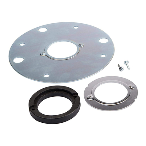
Triton
Triton TGA250 Operating/safety instructions
Parkside
Parkside POF 1200 C2 Translation of the original instructions
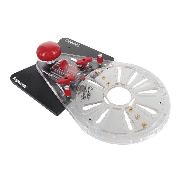
Milescraft
Milescraft Edge&MortiseGuide 1224 instruction manual

MaxPro PROFESSIONAL
MaxPro PROFESSIONAL MPER2000/12VGC manual
DeWalt
DeWalt DCW604 Original instructions
Makita
Makita RP1111C instruction manual
