Tyco Electronics DT-3000 Reference guide

409-10042
Customer Manual
Direct Drive Terminator (DT)-3000
Machines 1725100-[ ] and
LOC B
1
of 22
E
2008 Tyco Electronics Corporation, Harrisburg, A
All International Rights Reserved
TE logo and Tyco Electronics are trademarks.
*Trademark. Other products, logos, and company names used are the property of their respective owners.
TOOLING ASSISTANCE CENTER 1-800-722-1111 This controlled document is subject to change.
For latest revision and Regional Customer Service,
visit our website at
www.tycoelectronics.com
21 JUL 08 Rev E
DT-5000 Machines 1725800-[ ]
EAD THIS FI ST !
2..........................
SAFETY PRECAUTIONS
1. INT ODUCTION
3....................................................
2. DESC IPTION
5......................................................
2.1. Functional Description 5.............................................
2.2. Electrical Description 7..............................................
3. ECEIVING INSPECTION AND INSTALLATION
8.............................
3.1. Receiving Inspection 8..............................................
3.2. Installation 8.....................................................
3.3. Considerations Affecting the lacement of Bench Machines 9..................
4. OPE ATION
10......................................................
4.1. Control anel Operation 10..........................................
4.2. Applicator Installation 10............................................
4.3. Setup 11........................................................
4.4. Mode Selection and Operation 11......................................
4.5. End-Feed/Side-Feed Applicator Conversion 14...........................
5. P EVENTIVE MAINTENANCE
15........................................
5.1. Cleaning 15.....................................................
5.2. Lubrication 15....................................................
6. ADJUSTMENTS
16....................................................
6.1. Shut-Height Adjustment 16..........................................
6.2. Crimp Height Adjustment Using recision Adjustment Mechanism 17............
7. MACHINE OPTIONAL ACCESSO IES
17...................................
7.1. Conversion Adapter Kits 1725156-[ ] 18.................................
7.2. Lubricator Bowl Assembly 354550-3 19.................................
7.3. Air Feed Kit 1424266-[ ] 19..........................................
8. T OUBLESHOOTING
22...............................................
9. EVISION SUMMA Y
22...............................................

409-10042
DT-3000 Machines 1725100-[ ] and DT-5000 Machines 1725800-[ ]
Rev
E2
of 22 Tyco Electronics Corporation
SAFETY PRECAUTIONS AVOID INJURY
Safeguards are designed into this application equipment to protect operators and maintenance personnel from
most hazards during equipment operation. However, certain safety precautions must be taken by the operator
and repair personnel to avoid personal injury, as well as damage to the equipment. For best results, application
equipment must be operated in a dry, dust–free environment. Do not operate equipment in a gaseous or
hazardous environment.
Carefully observe the following safety precautions before and during operation of the equipment:
D
ALWAYS wear appropriate ear protection.
D
ALWAYS wear approved eye protection when operating powered equipment.
D
ALWAYS keep guard(s) in place during normal operation.
D
ALWAYS insert power plug into a properly grounded receptacle to avoid electrical shock.
D
ALWAYS turn off the main power switch and disconnect electrical cord from the power source when
performing maintenance on the equipment.
D
NEVER wear loose clothing or jewelry that may catch in moving parts of the application equipment.
D
NEVER insert hands into installed application equipment.
D
NEVER alter, modify, or misuse the application equipment.
TOOLING ASSISTANCE CENTER
CALL 021-538318188
DANGER

409-10042
DT-3000 Machines 1725100- ] and DT-5000 Machines 1725800- ]
R v
E 3
of 22
Tyco El ctronics Corporation
Front View Back View
DT-3000 Machine Shown
DT-3000 or DT-5000 MACHINES STROKE (mm in.]) APPLICATOR Ċ MACHINE BASE PLATE
-1 30 [1.181] JAM Ċ Univ rsal
-2 30 [1.181] AMP Ċ Quick-Chang
-3 41.28 [1.625] AMP Ċ Quick-Chang
-4 30 [1.181] JAM Ċ Quick-Chang
-5 30 [1.181] JST Ċ Univ rsal
-6 30 [1.181] AMP Ċ Quick-Chang
H
-7 41.28 [1.625] AMP Ċ Quick-Chang
H
Figure 1
H
Includ s Crimp Quality Monitor (CQM) S nsor
1. INTRODUCTION
This manual contains information on operation, preventive maintenance, and adjustments of DT–3000
Machines 1725100–[ ] (shown in See Figure 1) and DT–5000 Machines 1725800–[ ]. Descriptions in this
manual pertain to the controls and adjustments on these machines
only
.
The machines are intended for use with (AMP) Tyco Electronics applicators, JAM (Toyojamco Ltd.) applicators,
and JST (JST Manufacturing Company Ltd.) applicators as indicated in Figure 1. All of these machines are
restricted to China.
When reading this manual, pay particular attention to DANGER, CAUTION, and NOTE statements.

409-10042
DT-3000 Machines 1725100-[ and DT-5000 Machines 1725800-[
Rev
E4
of 22 Tyco Electronics Corporation
Deno es an imminen hazard which may resul in modera e or severe injury.
Deno es a condi ion which may resul in produc or equipmen damage.
Highligh s special or impor an informa ion.
Reasons for reissue are in Section 9, REVISION SUMMARY.
The various applica ors ha can be used in hese machines are covered in applica or ins ruc ion shee s packaged wi h
each applica or. Applica or ins ruc ion shee s provide informa ion on applica or ins alla ion, care, and adjus men .
All numerical values are in me ric uni s [wi h U.S. cus omary uni s in bracke s]. Some commercial i ems may
con ain non-me ric hardware.
Figure 2 provides specifications and requirements for these machines.
Capacity (Maximum Crimp Force):
DT-3000 Machines 13.3 kN [3,000 lb]
DT-5000 Machines 22.2 kN [5,000 lb]
Deflection:
0.13 mm [.0046 in.] Maximum per 4,448 Newtons [1,000 lb] Crimp Force
Noise:
Less than 76 dBa Typical at Operator osition with Standard Mechanical Feed Applicator
Weight:
64 Kilograms [143 lb]
Height:
510 mm [20 in.] Without Reel Supports
Electrical:
100-240 Vac, 50/60 Hz, Single- hase Current
Air:
620-760 k a [90-110 psi], 2.83 liters/sec (6 scfm)
When Required for Use with Air-Feed Applicators
Figure 2
Physical Environment:
Temperature: 4.4
°
-40
°
C [40
°
-104
°
F]
Altitude: Not Applicable
Relative Humidity: Less than 95% (non-condensing)
Transportation and Storage: Store in a clean, dry environment after coating all surfaces
lightly with a rust-preventing oil.
DANGER
CAUTION
!
NOTE
i
NOTE
i
NOTE
i

409-10042
DT-3000 Machines 1725100- ] and DT-5000 Machines 1725800- ]
Rev
E 5
of 22
Tyco Electronics Corporation
2. DESCRIPTION
These machines were designed to be used as a stand–alone semi–automatic bench unit. It is assembled with
metric hardware.
A precision adjustment feature on the machine provides quick and accurate crimp height adjustments. The
batch counter provides a count of the terminations. A work light is included with the machine.
The base plate of Machines –6 and –7 also include a CQM sensor.
These machines accept a wide variety of miniature (mini) quick–change applicators, with minor adjustments,
thus providing a great selection of terminals for many applications. Figure 3 lists changeover cams required to
run 30–mm [1.181–in.] stroke cams (for AMP–O–LECTRIC* Model “K” terminating machines) and 41.28–mm
[1.625–in.] stroke cams (for Model “T” and Model “G” terminating machines) in these machines.
Some heavy-duty mini applicators require special cams that are not listed in Figure 3. Refer to the applicator logs
shipped with the applicators for additional information.
ORIGINAL APPLICATOR FEED TYPE
CHANGEOVER CAMS
FOR DT-3000 AND DT-5000 MACHINES
ORIGINAL APPLICATOR
FEED TYPE
-2 and -6 -3 and -7
30-mm
1.181-in.
]
Stroke A
pp
licator for Pre-Feed Ċ 690602-6
]pp
Model K" Terminating Machine Post-Feed Ċ 690501-4
41.28-mm
1.625-in.
]
Stroke A
pp
licator for Pre-Feed 690602-5 Ċ
]pp
Model T" and Model G" Terminating Machines Post-Feed 690501-3 Ċ
Heavy-Duty Industrial (HD-I) Applicator Pre-Feed/Post-Feed Refer to the HD-I Applicator Customer Drawing
For Part Numbers
Figure 3
Quick–Disconnect Coupling 23238–1 is required to run air–feed applicators.
End–feed and side–feed miniature applicators are easily installed and removed without repositioning the
applicator mounting plate on the machine.
2.1. Functional Description
These machines provide the force required to crimp terminals in the applicator. A terminal is attached to the
wire by placing the wire in the crimp area and pressing the foot switch. The machine consists of four functional
areas:
1. The
motor group
includes a dc motor which drives a crankshaft. The motor is activated each cycle
and rotates the crankshaft one full revolution. A motor access cover, located on the end of the motor,
covers a hex key which allows the motor to be cycled manually. See Figure 4.
2. The
crankshaft–ram group
covers the motor rotational force to the up–and–down action of the ram
for driving the applicator during the crimping cycle.
3. The
base plate
provides the mounting surface on which the applicator is installed. The quick–release
latching feature on Machines –2, –3, –4, –6, and –7 permits fast, easy installation and removal of the
applicator. Note that Machines –1 and –5 do not include the quick–release latching feature.
See Figure 5.
4. The
crimp height adjustment group
uses an eccentric located in the ram linkage, along with
detented stops in the mechanism to adjust the crimp height. See Figure 5. Indexing the mechanism in
either direction will change the crimp height in increments of approximately 0.013 mm [.0005 in.] per
step.
NOTE
i

409-10042
DT-3000 Machines 1725100-[ ] and DT-5000 Machines 1725800-[ ]
Rev
E6
of 22 Tyco E ectronics Corporation
Figure 4
DC Motor
Crankshaft
Motor Access Cover
Figure 5 (Cont’d)
Base P ate for Machines
-2, -3, -6, and -7
Quick-Re ease
T-Hand e
Precision Crimp Height
Adjustment Mechanism
Base P ate for Machines
-1 and -5
A ternate Rear Stop
Mounting Position

409-10042
DT-3000 Machines 1725100-[ ] and DT-5000 Machines 1725800-[ ]
Rev
E 7
of 22
Tyco Elect onics Co po ation
Figure 5 (End)
Swing Handle
Base Plate fo Machines -4
2.2. Electrical Descri tion
The electrical components of these machines consist of the operator control panel, the motor, and the
CPU/motor controller package. The machine operates on 100/240 Vac, 50/60 Hz, single–phase current with
ground. The machine will automatically detect the supply voltage and adjust the controller accordingly.
The operator control panel (Figure 6) is mounted on the left side of the machine frame. The control panel
consists of an indicator light, a jog button, and a speed control knob, with icons depicting each function. See
Paragraph 4.1 for control panel operation.
A main power switch/circuit breaker (Figure 7) is located on the back of the machine. This switch connects ac
power to the control system. The CPU/motor controller is located behind the back cover of the machine. It is a
modular unit that contains all of the electronics necessary to operate the machine. See Figure 7.
The CPU/motor controller package for the DT–5000 machine includes a motor cooling fan. This fan runs when
the main power switch is on.
The CPU/motor controller package contains high voltages which can remain even after power has been removed.
Contact the Tooling Assistance Center at the number on the bottom of page 1 for precautionar measures to follow if
internal access to the CPU/motor controller is required.
Figure 6
G een Indicato
Jog Button Speed Cont ol Knob
Fault Icon
Machine Ready
Icon
Speed Cont ol
Icon
Jog Button Icon
Batch Counte
DANGER

409-10042
DT-3000 Ma hines 1725100-[ ] and DT-5000 Ma hines 1725800-[ ]
Rev
E8
f22 Tyc Electr nics C rp rati n
Figure 7
DC M t r
Back C ver
CPU/M t r C ntr ller
(Behind Back C ver)
M t r Access
C ver
Reel Supp rt H le
P wer Switch/Circuit Breaker
Terminal
Strip Guide
H le f r Cust mer Supplied
Lift Ring
3. RECEIVING INSPECTION AND INSTALLATION
3.1. Re eiving Inspe tion
The machines are thoroughly inspected during and after assembly. A final series of inspections is made to
insure the proper machine functioning before packaging and shipping.
To protect against damage that may have occurred during shipment, remove the machine from the crate
(Paragraph 3.2) and carefully inspect the machine for damage. If damage is evident, file a claim against the
carrier and notify Tyco Electronics immediately.
3.2. Installation
Remove all mounting bolts securing the machine to the shipping pallet. Install lift ring (refer to Figure 7) on top
of the machine.
Lift ring (M12
20 eye bolt) is customer supplied.
Install the lift ring
carefully
. A 19.05-mm [.75-in.] thread length engagement is re uired for the lift ring to support the
machine.
Attach a suitable hoist to the lift ring, lift the machine, and place it in the selected operating location.
NOTE
i
CAUTION
!

409-10042
DT-3000 Machin s 1725100-[ ] and DT-5000 Machin s 1725800-[ ]
Rev
E 9
of 22
Tyco Electronics Corporation
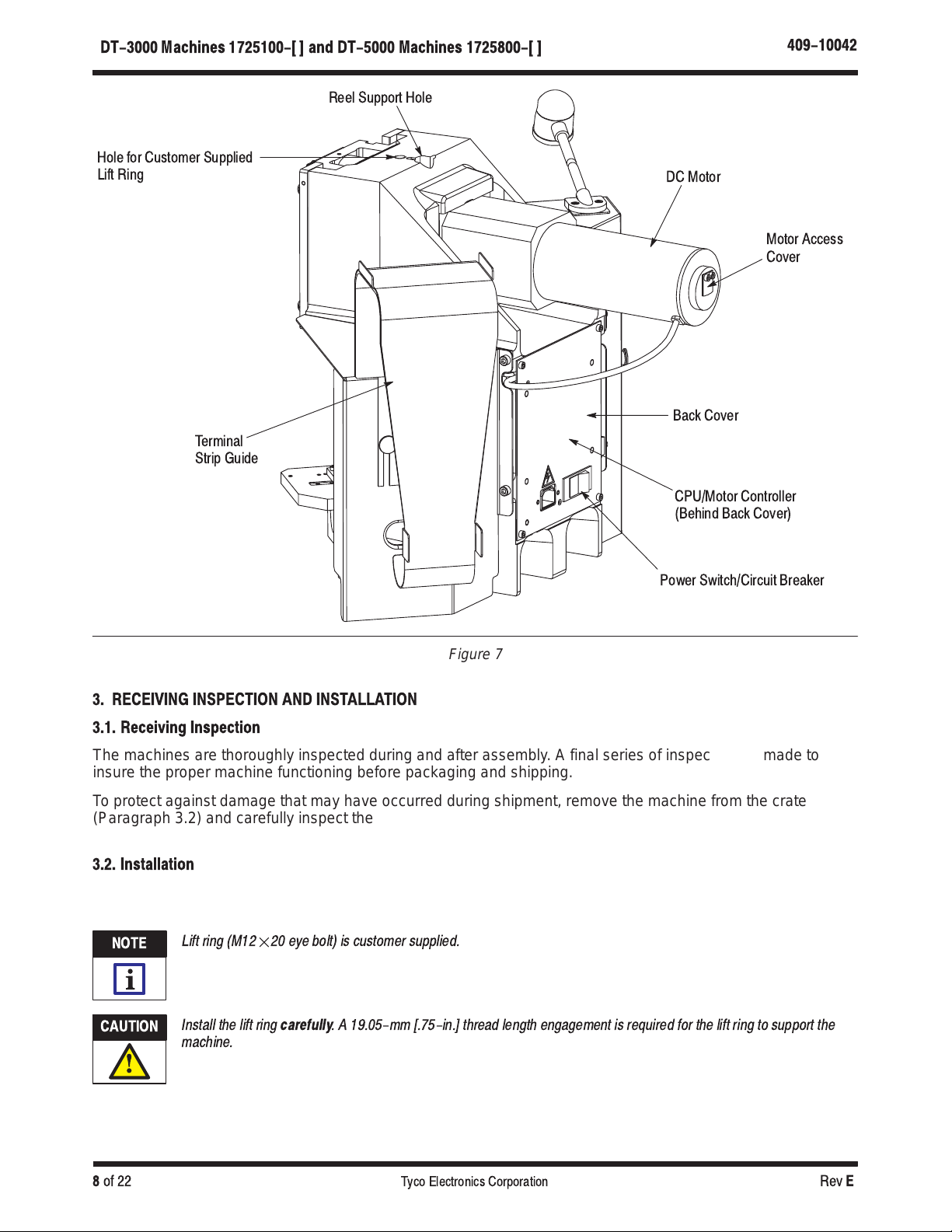
Insert the reel support post into the appropriate hole on top of the machine (Figure 7) until the roll pin engages
a groove in the machine frame.
Attach the terminal strip guide included with the machine with the two thumbscrews supplied. Mount the guide
on the left guard for side–feed applicators. Mount the guide on the right guard for end–feed applicators.
Connect a suitable power cord (not included with the machine) to the machine, then connect the power cord to
a suitable electrical supply.
The machine will automatically detect the supply voltage and adjust the controller accordingly.
3.3. Consid rations Aff cting th Plac m nt of B nch Machin s
The location of the machine in relation to the operator’s position is extremely important in terms of both safety
and maximum efficiency. Studies have repeatedly shown that operator fatigue will be reduced, and greater
efficiency achieved, if:
1. the bench is of appropriate height, preferably with sound–deadening rubber mounts;
2. the machine is properly located on the bench with ample work areas on both sides to facilitate work
flow;
3. the operator uses a swivel chair with padded seat and back rest which are independently adjustable;
and
4. the foot switch, on machines so equipped, is placed on a rubber mat to maintain its movability, while
preventing it from sliding unintentionally.
Figure 8 illustrates proper machine location and operator position and the following:
A. B nch
The bench to be used should be of sturdy construction, preferably with rubber mounts to minimize noise.
A height of 762 to 812.8 mm [30 to 32 in.] is the most suitable for operator comfort and convenience. This
height allows the operator to rest both feet on the floor, thereby providing for the shifting of weight and leg
position.
B. Machin Location on B nch
The machine should be located near the front of the bench with the “target area” (tooling area where the
product is applied) not more than 152.4 to 203.2 mm [6 to 8 in.] from the front edge. This location will
eliminate unnecessary operator motion and help to avoid back strain and fatigue.
Orientation of the machine should be such that the “target area” is facing the front of the bench and is
parallel to the front edge (access to the back of the machine MUST also be provided).
The machines have provisions for being bolted to the bench.
C. Op rator's Chair
The operator’s chair should swivel, and should have independent seat height and back rest adjustments.
The seat and back rest should be padded, and the back rest should be large enough to provide support
both above and below the waist line.
In use, the chair should be far enough under the bench so that the operator’s back is straight and is
supported by the back rest.
D. Foot Switch
When the operator is correctly positioned in front of a machine equipped with a foot switch, the foot should
rest on the switch comfortably. The foot switch should be movable, so that its location can be readily
changed when the operator shifts position to minimize fatigue. Placing the switch on a rubber mat keeps it
movable while preventing unintentional sliding.
NOTE
i
NOTE
i

409-10042
DT-3000 Mac ines 1725100-[ ] and DT-5000 Mac ines 1725800-[ ]
Rev
E10
of 22 Tyco Electronics Corporation
The preferred foot switch location varies to some extent among operators. Some operators prefer the
switch located so that their foot rests on the switch when their feet are in the natural sitting position (calf of
leg perpendicular to the foot). Others prefer the leg to be slightly in front of the natural position. The
important thing to remember is that the foot should be at approximately 90
_
(right angle) to the calf when
resting on the switch. Those operators who prefer the foot switch slightly in front of the natural position
may require a wedge–shaped block placed under it.
E. Scrap Removal
A suggested method of scrap removal: place a tray on the right side of the machine, under the cast slot in
the frame, to capture the scrap chips.
Applied
Product
Supply
Figure 8
Materials LocationsĊPlan ViewMachine Location and Operator Position
4. OPERATION
4.1. Control Panel Operation
The basic control panel operation is as described in Figure 9. The control panel will be used to set up and
operate the machine (see Paragraphs 4.3 and 4.4).
4.2. Applicator Installation
Machines –1 and –5 require the use of a hex wrench to change applicators. Since these machines have a
universal base plate, they can be configured to use AMP, JAM, or JST applicators.
Machines –4 (intended for use with JAM applicators and have a quick–change base plate) do not require tools
to change applicators. This base plate features a swing handle used to install and remove the applicator.
The following instructions apply to Machines –2, –3, –6, and –7 (intended for use with AMP applicators and
have a quick–change base plate). Install the applicator in the base plate as follows:
If the machine is equipped with a precision adjustment feature, make sure that the precision adjustment ever has
been returned to the 0" position before insta ing the app icator. Be sure that the app icator has the proper feed cam
prior to insta ation.
App icators from AMP-O-LECTRIC Mode K" terminating machine and Mode T" terminating machine can be used in
the machine by using a specia rep acement cam. Refer to Figure 3.
1. Loosen the quick–release T–handle (see Figure 5), and slide the applicator base clamp down.
CAUTION
!
NOTE
i

409-10042
DT-3000 Mac ines 1725100-[ ] and DT-5000 Mac ines 1725800-[ ]
Rev
E11
of 22
Tyco Electronics Corporation
2. Place the applicator on the quick–change base plate, then slide it back until the two notches in the
applicator base engage the stops at the back of the quick–change base plate. At the same time, guide
the ram post into the ram post adapter.
3. Slide the applicator base clamp UP and re–tighten the quick–release T–handle to secure the
applicator in place.
When using Applicator 567200-2 (originally intended for use with AMP-O-LEC RIC Model K" terminating machine),
loosen the quick-release -handle, slide down the applicator base clamp, and remove the rear stop located on the left
side of the base plate. Install the rear stop (PN 354561-1), supplied with the air feed kit (optional accessory), at the
alternate mounting position on the base plate. See Figure 5.
4. Set the crimp height and insulation crimp discs so that the letters and numbers on the applicator pad
align with the front pad on the ram post adapter.
5. If the applicator is an air–feed type, connect the airlines to the valves located on the back of the
machine.
Quick Disconnect Coupling 23238-1 is required to run air-feed applicators.
6. Adjust the reel support for side–feed or end–feed product, depending on the applicator being used.
7. Mount the terminal strip guide on the left sheet metal guard for side–feed product, or on the right
sheet metal guard for end–feed product, depending on the applicator being used.
8. Mount the terminal reel on the reel support. Thread the terminal strip through the guard and into the
applicator according to the instruction sheet included with the applicator. If necessary, adjust the
lubricator bowl.
9. Align the product reel to the applicator by adjusting the reel flanges.
4.3. Setup
Install a miniature applicator and terminals according to Paragraph 4.2.
1. Turn on the main power using the switch located on the back of the machine.
2. Jog the machine (as described in Paragraph 4.4, B) through a complete crimp cycle.
Machine should be able to jog through the terminal and wire at maximum jog speed to determine crimp capacity.
3. Inspect the crimped terminal to verify that the terminal is being positioned properly within the
applicator.
4. Correct for any positioning errors according to the applicator instruction sheet, and repeat Steps 2
and 3 until a terminal is properly positioned.
5. Place a prepared wire in the crimp area and press the foot switch.
6. Inspect the completed crimp and make adjustments as necessary.
4.4. Mode Selection and Operation
The two basic modes of operation for these machines are: Full–Cycle and Jog.
A. Full-Cycle Mode
Depressing the footswitch causes the crankshaft to be rotated (at a speed defined by the speed control
knob), through a complete revolution. This completes one full machine cycle.
B. Jog Mode
(Figure 9)
Pressing the Jog button causes the crankshaft to be rotated at a default–reduced speed in the forward
direction until the Jog button is released or the crankshaft completes the cycle. If the Jog button is
NOTE
i
NOTE
i
NOTE
i

409-10042
DT-3000 Machi es 1725100-[ ] a d DT-5000 Machi es 1725800-[ ]
Rev
E12
of 22 Tyco Electronics Corporation
released in mid–cycle and pressed again, the crankshaft will continue to rotate in the forward direction at
the default reduced speed. If the machine does not complete the cycle, either adjust the speed control
knob (as described below), or complete the cycle using the footswitch (at a speed determined by the
speed control knob) after the Jog button has been pressed and released.
Holding the Jog button down for more than five seconds will cause the machine to “err.” To clear the error,
“power down” the machine, clear the problem area, and then “power up” the machine again. An alternate
method of clearing the error is to hold down the foot pedal until the green status indicator stops flashing. If
the motor is stalled, it may be necessary to manually cycle the machine to the home position. Refer to the
CAUTION and DANGER statements below for the proper manual cycling procedure.
While in the Jog mode, attem ting to com lete a crim cycle with terminals and wire in the a licator may cause the
motor to stall. Although the machine can terminate some smaller terminals and wire, it may be necessary to turn off"
the machine and manually cycle the machine to the home osition. Manually cycle the machine by removing the
access cover on the end of the motor (Figure 7), engaging the hex key with a 6-mm hex wrench, and rotating the key
to manually rotate the motor.
To avoid ersonal injury, be sure to remove the hex wrench before o erating the machine under ower. Be sure to
re lace the access cover.
To avoid ersonal injury, exercise caution when jogging or o erating the machine.
CAUTION
!
DANGER
DANGER

409-10042
DT-3000 Machines 1725100-[ ] and DT-5000 Machines 1725800-[ ]
R v
E 13
of 22
Tyco El ctronics Corporation
Figure 9
Gr n Indicator Jog Button Sp d Control Knob
Fault Icon
Machin R ady Icon
Sp d Control Icon
Jog Button Icon
Th y llow and gr n indicators on th top of th control pan l indicat th machin status.
Wh n th gr n indicator is on" and is
not
flashing, th machin is r ady for op ration.
Wh n th gr n indicator is flashing, a machin fault has b n d t ct d. To r s t th machin , pow r
down" th machin , cl ar th probl m ar a, and th n pow r up" th machin ; or hold down th foot
p dal until th gr n indicator stops flashing.
Th Jog button icon indicat s int rmitt nt op ration at a slow r sp d wh n using th Jog button.
Th Jog button allows th op rator to cycl through various stag s of th machin cycl .
Th Sp d Control knob d t rmin s th machin sp d (activ in both normal op ration and Jog op ration)
Sp d incr as s as th knob is turn d
CLOCKWISE
.
Sp d Rang s: From 100% to 60% with th foot p dal
From 60% to 25% with th Jog button
Batch Count r

409-10042
DT-3000 Machines 1725100-[ and DT-5000 Machines 1725800-[
Rev
E14
of 22 Tyco Electronics Corporation
Adjusting the Speed Control Knob
The default speed of the crankshaft in the Jog Mode is set to a minimum initial value which is
not
defined
by the initial position of the speed control knob. Adjusting the speed upwards enables jogging at speeds
greater than the default in case greater speeds are required to complete a cycle. To cause the crankshaft
to rotate at other than the initial default speed, the speed control knob must be rotated completely
counterclockwise
, then rotated back
clockwise
to the desired speed setting. If the Jog button is depressed
within three seconds of setting the speed control knob, the crankshaft will rotate at the speed defined by
the position of the speed control knob. The new speed setting will remain active for a maximum of three
seconds after the Jog button is released, or until the crankshaft completes the cycle. If the cycle is not
complete and the Jog button is again pressed within three seconds from its release, the crankshaft will
rotate at the speed defined by the position of the speed control knob. Failure to push the Jog button within
the three seconds of its release will cause the crankshaft jog speed to revert back to the initial minimum
default value. After the Jog button is released, the speed control knob can be rotated in either direction to
increase or reduce the crankshaft jog speed, but Jog button must be activated again within three seconds
of the release or the speed will revert back to minimum default speed. The speed control knob can be
reset as many times as desired.
The ram may drift dow ward if the Jog butto is released i mid-stroke.
The speed co trol k ob (Figure 9) also adjusts the air feed timi g. Normally the air feed timi g is set at 280 ms. Whe
the speed co trol is set at less tha 50% of its maximum setti g (poi ti g straight dow or cou terclockwise from
poi ti g straight dow ), the air feed timi g cha ges to 440 ms. This is do e to accommodate applicators that have
lo ger tha ormal air cyli ders.
The green flashing status indicator flashes a specific number of times to represent a corresponding fault. For
example, the green status indicator will flash five times (each followed by a one second pause) to indicate that
the top–dead–center (TDC) switch was not sensed while the machine was running. Refer to Figure 10.
FAULT INDICATOR CODE
(Number of Consecutive Flashes) MACHINE FAULT
4 Motion from TDC was not detected.
5 T e TDC switc was not sensed.
6 A bad PWM IGBT was detected.
7A bad Jog pus button input was detected.
8A bad footswitc input was detected.
9 A bad DC bus relay was detected.
10 A bad jog enable input was detected.
11 T e line voltage is not wit in specifications.
12 A bad spare input was detected.
Figure 10
4.5. End-Feed/Side-Feed Applicator Conversion
When changing from an end–feed applicator to a side–feed applicator (or from a side–feed applicator to an
end–feed applicator), the reel support assembly must be moved to the opposite side of the machine. With the
terminal reel removed, lift and rotate the reel support bar to the opposite side of the machine. Mount the
terminal reel on the reel support and load the terminal strip into the applicator. Remove the metal terminal
lead–in and thumbscrews and move to the opposite side of the machine. If installed, move the lubricator bowl
to the opposite side of the machine as required.
The lubricator bowl is a optio al accessory.
NOTE
i
NOTE
i
NOTE
i

409-10042
DT-3000 Machines 1725100-[ ] an DT-5000 Machines 1725800-[ ]
Rev
E 15
of 22
Tyco Electronics Corporation
5. PREVENTIVE MAINTENANCE
Preventive maintenance will keep the machine in good working order and ensure maximum reliability and
service from all of its components.
To avoid personal injury, electrical and pneumatic power must be DISCONNECTED at t e source prior to
maintenance.
5.1. Cleaning
Clean any debris from the applicator area daily.
Compressed air used for cleaning must be reduced to less t an 207 kPa [30 psi] and effective c ip guarding and
personal protective equipment (including eye protection) must be used.
If an air–feed assembly is installed, check and replace the air filter element if necessary.
5.2. Lubrication
The moving parts of the machine require regular lubrication to ensure reliable service and long life. Use only
CHEVRON Ultra Duty Grease EP National Lubricating Grease Institute (NLGI) 2, PENNZOIL PENNLITH Ultra
Grease EP NLGI 2, or CONOCO SYNCON Heavy Duty Grease EP.
For operation in temperatures below 10
_
C [50
_
F], it will be necessary to use a No. 1 grease.
Using a grease gun, apply grease every 250,000 cycles to the fittings at the following locations and as shown
in Figure 11:
S
the left side of the ram assembly;
S
the right side of the ram assembly;
S
the left side of the frame just behind the ram assembly at two places; and
Give one pump of grease w ile t e ram is near t e top of its stroke and one pump of grease w ile t e ram is near t e
bottom of its stroke for best distribution of grease around t e bearing.
S
the crimp height adjuster pivot pin.
Chevron is a trademark of Chevron Corporation.
Penn oil and Pennlith are trademarks of Penn oil-Quaker State Company Corporation.
Conoco and Syncon are trademarks of Conoco Inc. Corporation.
DANGER
DANGER
NOTE
i
NOTE
i

409-10042
DT-3000 Machines 1725100-[ ] and DT-5000 Machines 1725800-[ ]
Rev
E16
of 22 Tyco Electronics Corporation
Figure 11
Lubrication Points
Lubrication Points
Precision Crimp Hei ht
Adjustment Mechanism
6. ADJ STMENTS
The following adjustments are necessary to maintain the machine in operating condition, and to set up the
machine after replacing parts.
T av id pers nal injury, ALWAYS disc nnect electrical and air supplies bef re perf rming adjustments.
6.1. Shut-Height Adjustment
The shut height is pre–set at the factory and should not require further adjustment unless it is necessary to
replace parts. In this case, and before making any changes to the machine, contact your local representative,
or call the Tooling Assistance Center at the number on the bottom of page 1.
Periodic inspection of the shut height by a field engineer is recommended.
The following information is for Field Service Engineer use only:
MACHINES SH T-HEIGHT GAGE
(408-8535)
SH T HEIGHT
+0.025 mm [+.0010 in.]
(mm [in.])
-1, -4 679655-2 119.5 [4.705]
-2, -3, -6, -7 679655-3 135.79 [5.346]
-5 679655-2 with Adapter 1725684-1 or
679655-3 with Adapter 1725684-2 160.0 [6.299]
T av id pers nal injury, ALWAYS turn ff" the machine and disc nnect the p wer supply t the machine bef re
making any adjustments. If applicat r is an air-feed type, DISCONNECT air lines t valve l cated n the right side f
the machine.
DANGER
DANGER

409-10042
DT-3000 M chines 1725100-[ ] nd DT-5000 M chines 1725800-[ ]
Rev
E 17
of 22
Tyco Electronics Corporation
The miniature app icator is an integrated assemb y consisting of upper too ing, ower too ing, and adjustment
capabi ity. The app icator requires a fixed shut height; that is, the distance between the bottom of the ram and the base
mount when the ram is FULLY bottomed. The required adjustments for crimp height are made by using the wire and
insu ation discs within the app icator. Refer to the instruction sheet supp ied with the app icator for adjustment
procedures.
6.2. Crimp Height Adjustment Using Precision Adjustment Mech nism
(Refer to Figure 12)
To avoid damaging the app icator, ALWAYS return the precision adjustment ever to the 0" position when finished
using the app icator.
1. Adjust the manual precision adjustment lever to “0” by pulling the lever away from the pivot pin. Lock
the lever in place by releasing it.
2. Install the applicator into the machine as described in Paragraph 4.2.
3. Cycle the machine to crimp three sample terminations. Check the crimp height of the samples. If the
crimp heights are not correct, adjust the crimp height as follows:
a. move the precision adjustment lever to the right to increase the crimp height; or
b. move the precision adjustment lever to the left to decrease the crimp height.
Moving the precision adjustment ever in either direction wi change the crimp height by approximate y 0.013 mm
[.0005 in.] per step.
4. Repeat Step 3 until the appropriate crimp height is obtained.
To avoid damaging the app icator, ALWAYS return the manua precision adjustment ever to the 0" position when
finished using the app icator.
7. MACHINE OPTIONAL ACCESSORIES
The following optional accessories are available for these machines:
To avoid persona injury when insta ing optiona accessories, be sure to turn off" the machine, and disconnect it from
the power source.
NOTE
i
CAUTION
!
NOTE
i
CAUTION
!
DANGER

409-10042
D -3000 Machines 1725100-[ ] and D -5000 Machines 1725800-[ ]
Rev
E18
of 22 Tyco Electronics Corporation
Figure 12
Adjustment Lever Reading
(+" above 0.00 mm
[.000 in.] setting)
Read Full Step
.051mm
[.002 in.
+
2
Manual Precision
Adjustment Lever
Read Full Step
0.051 mm
[.002 in.
+
2
Read Half Step
0.064 mm
[.0025 in.
2
+
Read Half Step
0.064 mm
[.0025 in.
Read Full Step
0.051 mm
[.002 in.
3
--
Adjustment Lever Reading
(-" below 0.00 mm
[.000 in.] setting)
2
7.1. Conversion Adapter Kits 1725156-[ ]
The conversion adapter kit is used to modify any of these machines with 30–mm [1.181–in.] stroke length in
order to install another type of applicator as indicated below. When using these kits, inspection of the shut
height by a field service engineer is recommended.
CONVERSION ADAP ER KI
1725156
SHU HEIGH
+0.025 mm [+.001 in.]
(mm [in.])
O USE
APPLICA OR
-1 119.50 [4.705 JAM (Universal Base Plate)
-2 135.79 [5.346 AMP
-3 119.50 [4.705 JAM (Quick-Change Base Plate)
-4 160.00 [6.299 JST

409-10042
DT-3000 Machines 1725100-[ ] and DT-5000 Machines 1725800-[ ]
Rev
E 19
of 22
T co Electronics Corporation
7.2. Lubricator Bow Assemb y 354550-3
(Figure 13)
The lubricator bowl is used to apply a small amount of lubricant to terminals to prevent them from jamming in
the machine after the crimping process.
Figure 13
Lubricator
Bowl
Lubricator Bowl
Bracket
7.3. Air Feed Kit 1424266-[ ]
Install the optional air feed kit onto the machine as follows:
1. Remove the four mounting bolts securing the rear controller panel to the frame. Refer to Figure 14.
2. Remove the control panel from the machine, and pivot it in order to view the control board.
3. Insert the small end of the air feed cable assembly (see Customer Drawing 1424266) into the J7
socket. See Detail in Figure 14.
4. Install the control panel into the machine with the air feed cable assembly through the upper right
hand slot in the machine frame.
5. Remove the two bolts securing the rear of the left sheet metal guard.
6. Install Air Feed Bracket 1338977–1 to the frame (see Figure 16) using the two bolts securing the
sheet metal guard (Figure 14).

409-10042
DT-3000 Machines 1725100-[ ] and DT-5000 Machines 1725800-[ ]
Re
E20
of 22 Tyco Electronics Corporation
Rear Controller Panel
Mounting Bolts
Figure 14
Insert Small End of Air Feed
Cable Assembly Into J7 Socket
Detail
See Detail
Bolt Securing Sheet
Metal Guard
Air Feed Cable
Assembly
This manual suits for next models
1
Table of contents
Other Tyco Electronics Industrial Equipment manuals

Tyco Electronics
Tyco Electronics AMP-TAPETRONIC 69875 Reference guide

Tyco Electronics
Tyco Electronics 1752786-1 User manual

Tyco Electronics
Tyco Electronics EPP-0001-INT-4/10 User manual

Tyco Electronics
Tyco Electronics AMP 58246–1 User manual

Tyco Electronics
Tyco Electronics KILOVAC EV200 Series User manual

Tyco Electronics
Tyco Electronics CS 200 Reference guide

Tyco Electronics
Tyco Electronics FOSC-600 C User manual

Tyco Electronics
Tyco Electronics AMP NETCONNECT MRJ21 User manual

Tyco Electronics
Tyco Electronics AMP-O-LECTRIC 690675-2 User manual