CNC4PC C25S User manual
USER’S
MANUAL
C25S- SMOOTH STEPPER LPT
BOARD Rev. 1
APR, 2016

User’s Manual
Page i
USER'S MANUAL
TABLE OF CONTENTS
Page #
Contents
1.0 FEATURES.....................................................................................................................1
2.0 SPECIFICATIONS ..........................................................................................................1
3.0 FUNCTIONAL BLOCK DIAGRAMS ...............................................................................2
3.1 Inputs 10, 11, 12 13 and 15 (Port 1 and Port 2) Schematic ........................................2
3.2 Inputs 2-9 (Port 2) Schematic......................................................................................2
4.0 SET JUMPER IN THE S.S..............................................................................................3
5.0 WIRING DIAGRAMS.......................................................................................................3
5.1 Connecting Switches or push button .........................................................................3
5.2 Connecting NPN sensors (For any input)...................................................................4
5.3 Connecting PNP sensors (For any input)...................................................................6
5.4 Other connection (For any input)................................................................................7
6.0 DIMENSIONS..................................................................................................................8

User’s Manual
Page 1
1.0 FEATURES
•34 Inputs and Outputs on 2 ports.
•Full access to all the pins of the Smooth Stepper Board.
•Connects directly to the Smooth Stepper (from Warp9).
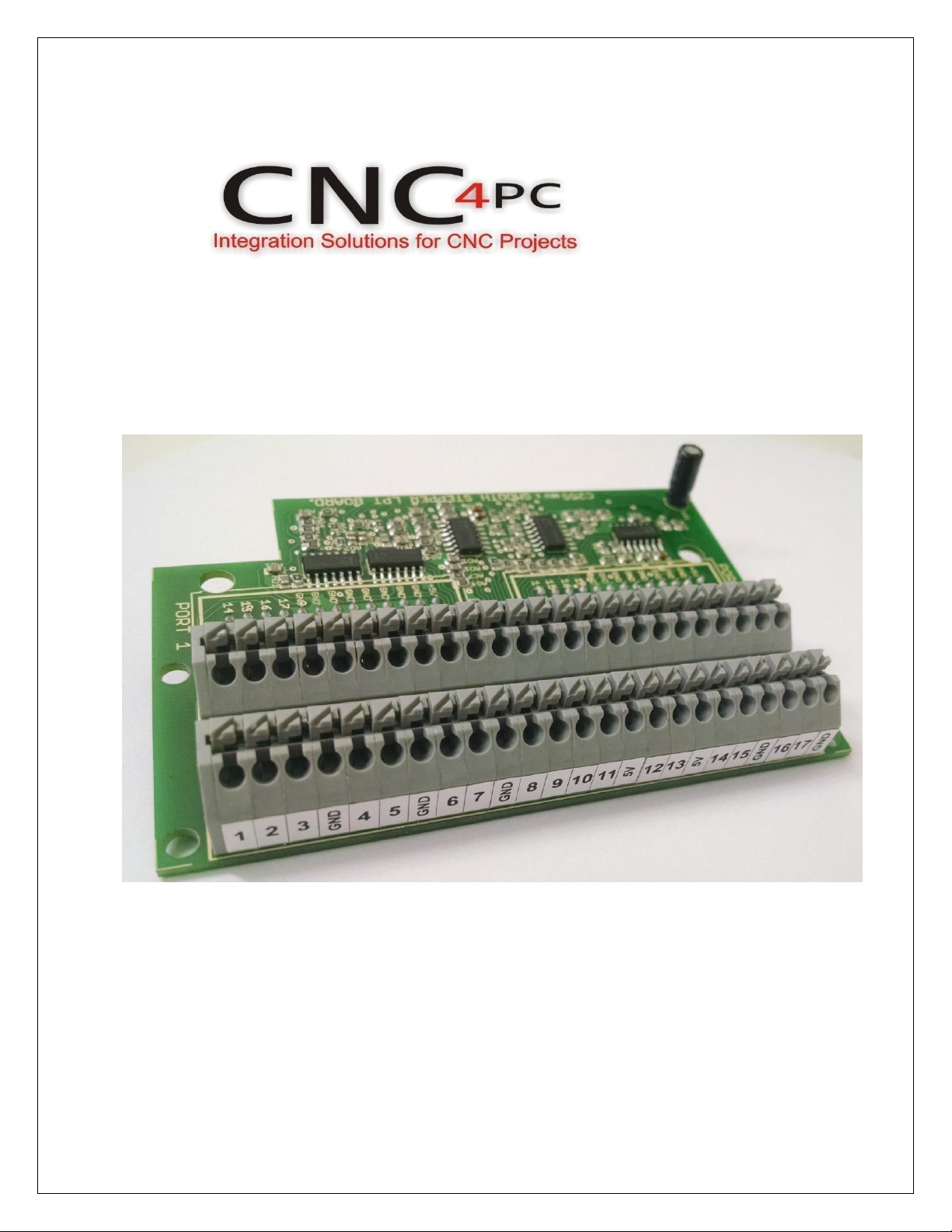
The board is provided with sockets that allow the Smooth Stepper Board to be
plugged directly into this board. No ribbon cables required. When using the
Smooth Stepper board there is no need to use an additional power supply to power
the board. It will draw power from the Smooth Stepper board.
•Built-in Passive Low Pass Filters for the all inputs.
This board includes lowpass filters to reduce the effect of the noisefrom the drivers
or other devices over the inputs signals.
•All TTL 5VDC signals.
Interface directly with parallel port interface products and other CNC4PC cards.
5VDC (TTL) cards are very common among automation devices.
•Input and output pins with close by ground connections.
Forget about grounding problems. Easily connect your pin by using your close by
ground connection. No need to be an electronics expert to ground all your stuff.
•Push-lock connections for all terminals.
You only have to push-lock the wires to make all your connections.
2.0 SPECIFICATIONS
DIGITAL INPUT SPECIFICATIONS
Numbers of inputs
5 on Port1, 13 on Port2
On-state voltage range
3.5 to 5V DC
Maximum off-state voltage
Aprox. 1.5V
Type
Active High
DIGITAL OUTPUT SPECIFICATIONS
Number of outputs
12 on Port1, 4 on port2
Maximum output voltage
(5V power supply voltage) +0.5V
Maximum off-state voltage
0.33 V
User’s Manual
Page 2
3.0 FUNCTIONAL BLOCK DIAGRAMS
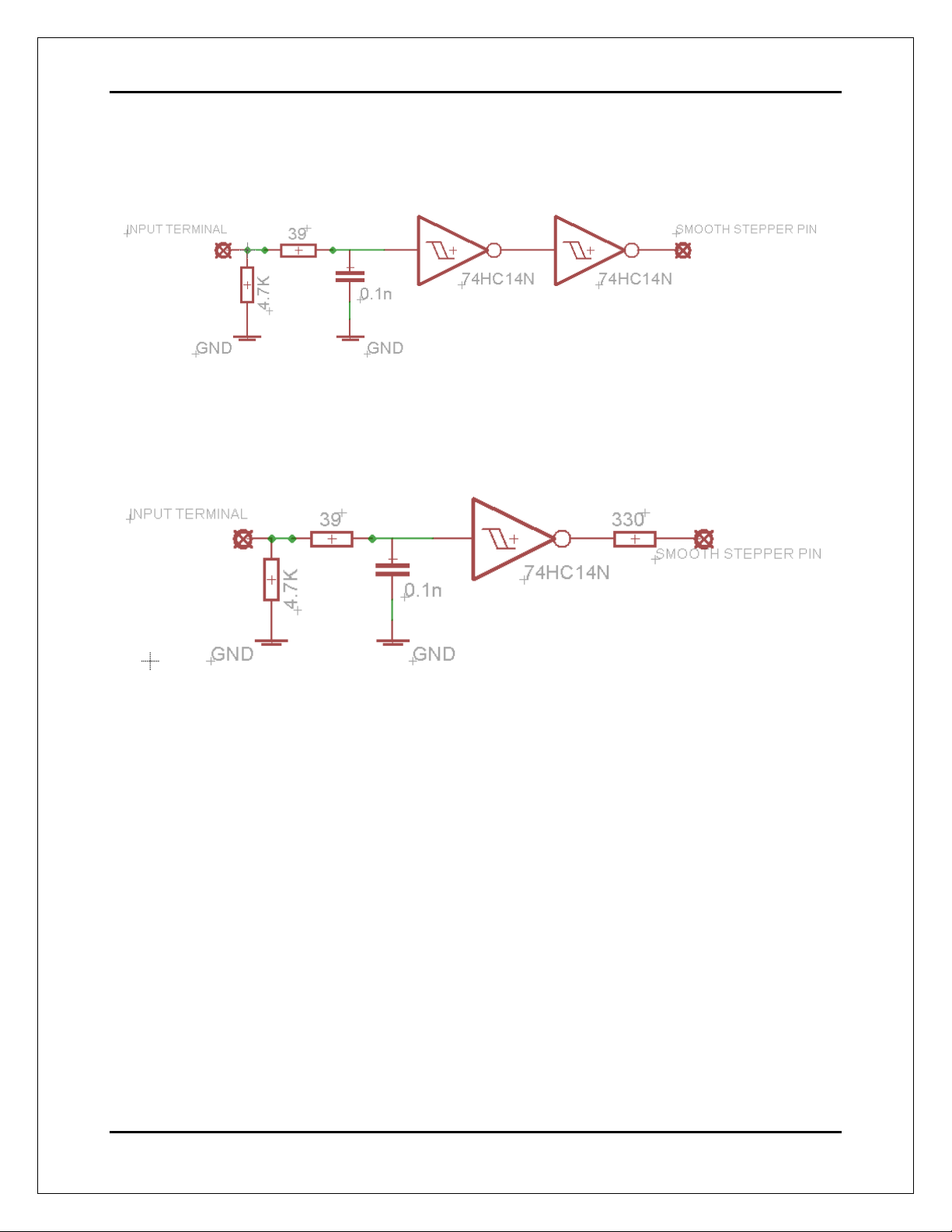
3.1 Inputs 10, 11, 12 13 and 15 (Port 1 and Port 2) Schematic
Simplified functional block diagram
Note: The Smooth Stepper includes an Schmitt Trigger in those input pins.
3.2 Inputs 2-9 (Port 2) Schematic
Using an RC Low Pass filter followed by a Schmitt Trigger gate will reduce the effect of
the noise from driver or other devices. This eliminates the high frequency components of
the noise and generating a fast changing signal.
Outputs 1, 14, 16 and 17 (Port 1 and 2) and outputs 2-9 (port 1).
All those pins are directly wired to the C25 output terminals.
User’s Manual
Page 3
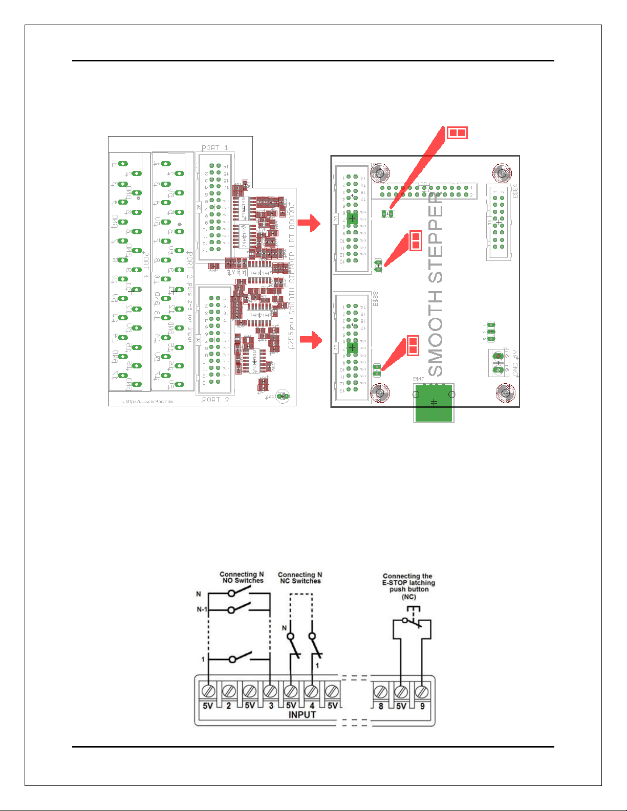
4.0 SET JUMPER IN THE S.S
5.0 WIRING DIAGRAMS
Different kind of sensors and switches can be connected to inputs board, but this board
support onlyTTL signal. If you need to connect devices that generates 12Vor 24V signals
in some cases is necessary add external resistors.
5.1 Connecting Switches or push button.

User’s Manual
Page 4
WIRING DIAGRAM TO CONNECT SWITCHES
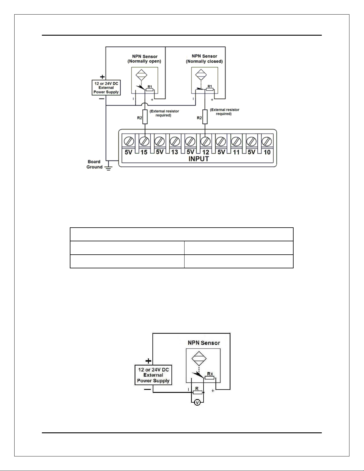
5.2 Connecting NPN sensors (For any input)
Wiring diagram to connect NPN open collector proximity sensors
WIRING DIAGRAM TO CONNECT IN PARALLEL NPN OPEN COLLECTOR
PROXIMITY SENSORS
Connecting NPN open collector proximity sensor with the C25
R1 Value (12V)
R1 Value (24V)
Aprox. 10KΩ
Aprox. 25KΩ
User’s Manual
Page 5
Wiring diagram to connect NPN proximity sensors with internal pull up resistor
Some NPN proximity sensors have an internal pull-up resistor (R1). It is necessary to
know its value in order to safely connect the sensor with the BOB. Follow this
recommendation:
Connecting NPN open collector proximity sensor with the C25
(R1+R2) Value (12V)
(R1+R2) Value (24V)
Aprox. 10KΩ
Aprox. 25KΩ
CALCULATING THE R1 VALUE
Note: Rx is the unknown resistor value.
RX = VEX.(R/V) - R (1)
User’s Manual
Page 6
Where:
VEX is the external power supply voltage
V is the voltage across the R resistor
A voltmeter is required to calculate the internal resistor value (Rx). Do the connection as
are shown in the figure above and do the calculations using the equation (1).
Note. R value has to be known to do this operation. A 4.7KOhm@1/2W is
recommended.
For example, if you are using a 12V power supply (VEX), and use a 4.7KOhm as
external resistor (R), and the voltage across R is 6V, using the equation 1, the Rx
value is 4.7KOhm.
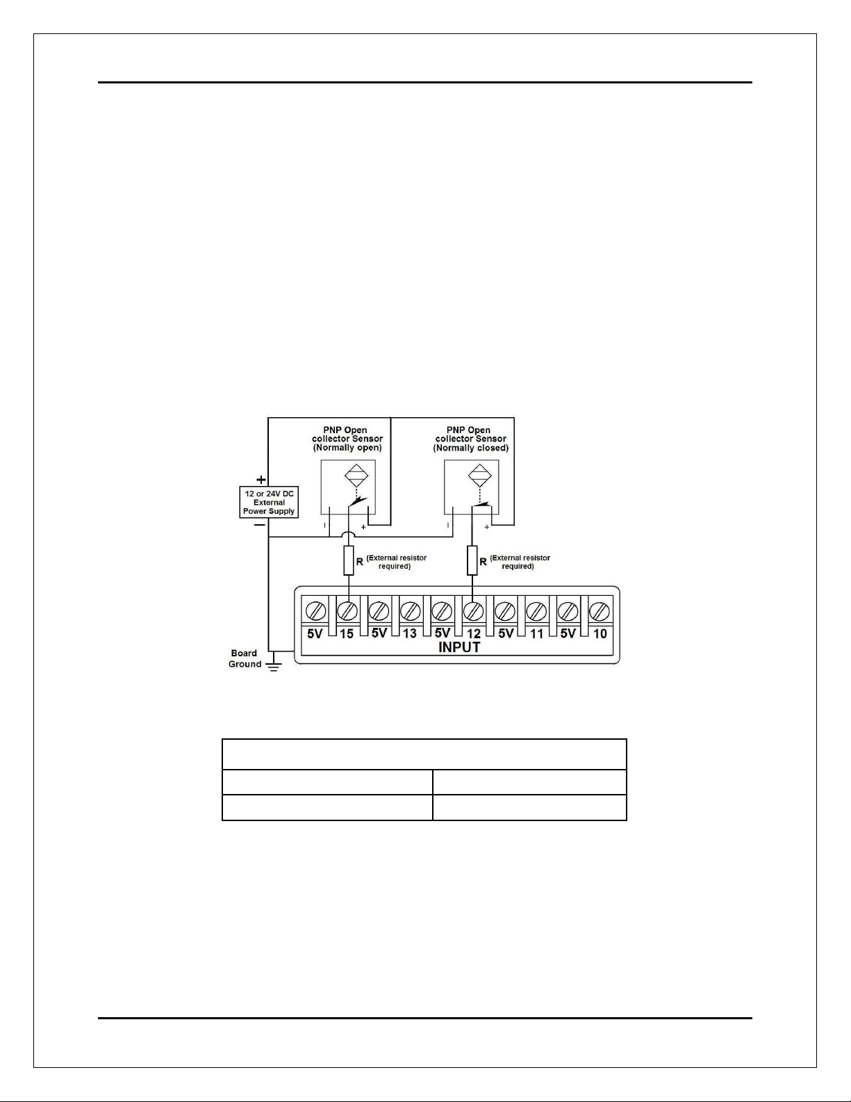
5.3 Connecting PNP sensors (For any input)
Wiring diagram to connect PNP proximity sensors
Connecting PNP proximity sensor with the C25
R Value (12V)
R Value (24V)
Aprox. 10KΩ
Aprox. 25KΩ
User’s Manual
Page 7
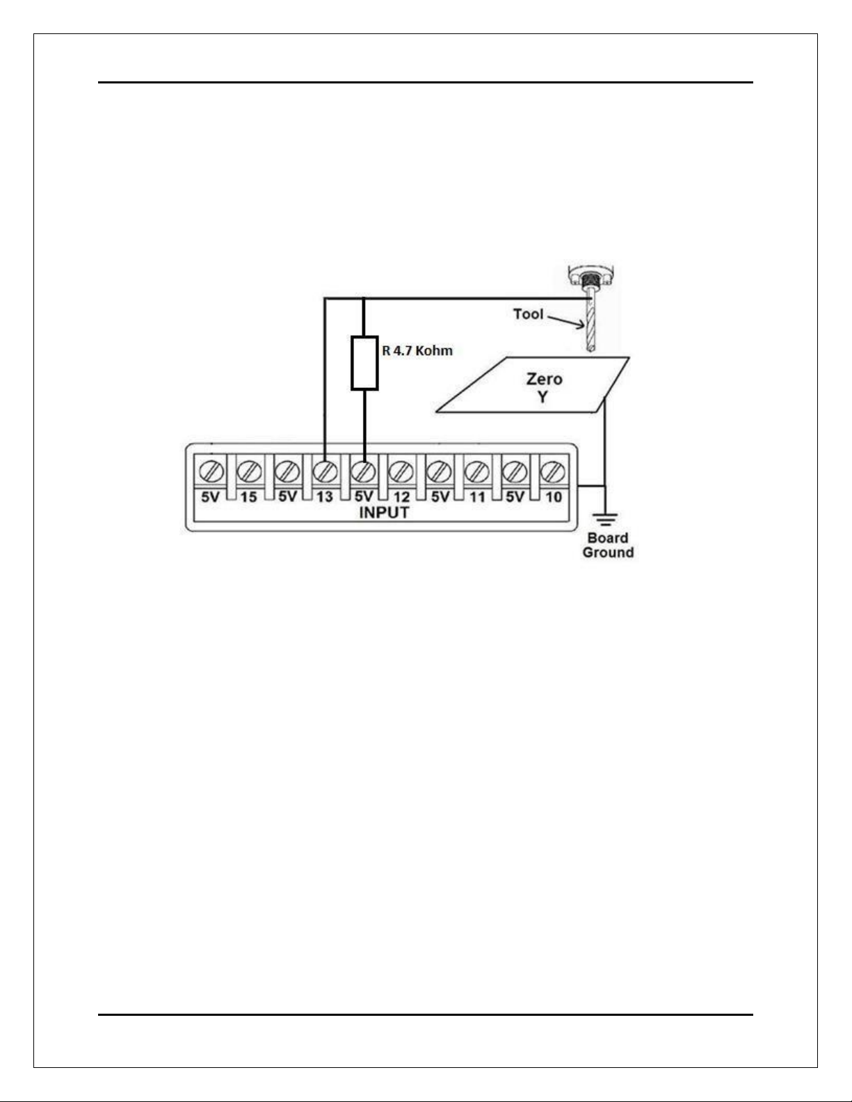
5.4 Other connection (For any input)
Other connections can be implemented by setting the inputs with pull-up resistor.
In this case connect an external 4.7KOhm resistor between the input terminal and
the 5V terminal.
Wiring diagram to do an “Auto Tool Zero”

User’s Manual
Page 8
6.0 DIMENSIONS
All dimensions are in Millimeters.
DISCLAIMER
Use caution. CNC machines can be dangerous machines. Neither DUNCAN USA, LLC
nor Arturo Duncan are liable for any accidents resulting from the improper use of these
devices. This product is not a fail-safe device and it should not be used in life support
systems or in other devices where its failure or possible erratic operation could cause
property damage, bodily injury or loss of life.
Table of contents
Other CNC4PC Motherboard manuals


