CNC4PC C11G User manual
User’s Manual
Page i
USER’S
MANUAL
VER.1
C11G- MULTIFUNTCION CNC BOARD
Rev. 9
MARCH, 2017

User’s Manual
Page ii
USER'S MANUAL
TABLE OF CONTENTS
Contents Page #
1.0 OVERVIEW.....................................................................................................................1
2.0 FEATURES.....................................................................................................................1
3.0 SPECIFICATIONS ..........................................................................................................2
4.0 BOARD DESCRIPTION..................................................................................................2
5.0 POWER TERMINALS AND CONFIGURATION JUMPERS............................................3
5.1 Power Terminal..........................................................................................................3
5.2 External Enable Pin...................................................................................................4
5.3 Led Indicator..............................................................................................................4
5.4 Safety Charge Pump “SCHP”. (Pin 17)....................................................................5
5.5 Controller selection jumpers (IEEE1284).................................................................6
6.0 VARIABLE SPEED CONTROL.......................................................................................7
6.1 Operation Mode Jumper............................................................................................7
6.2 Electromechanical relays. (Pin_1 or Pin_17) ..........................................................9
6.3 Using the COM configuration jumper.......................................................................9
7.0 FUNCTIONAL BLOCK DIAGRAMS .............................................................................10
7.1 Outputs 2-9 simplified functional block diagram ..................................................10
7.2 Outputs 1, 14, 16 and 17 simplified functional block diagram..............................10
7.3 Input simplified functional block diagram .............................................................11
7.4 Selection Jumper PULL-UP or PULL-DOWN .........................................................11
8.0 WIRING DIAGRAMS ....................................................................................................12
8.1 Connecting Switches or push button ....................................................................12
8.2 Connecting NPN sensors........................................................................................12
8.3 Connecting PNP sensors........................................................................................15
9.0 DIMENSIONS ...............................................................................................................16

User’s Manual
Page 1
1.0 OVERVIEW
This card has been designed to provide a flexible interface and functions to your
computer projects by using the parallel port or USB-based or Ethernet-based controller.
This board comes as a response to many customers that have been asking for a faster
way to connect devices and reduce the possibility of wiring errors.
2.0 FEATURES
•IEEE 1284 Standard compatible.
•PULL-UP or PULL-DOWN selection for inputs.
•Buffered inputs and outputs.
•Microcontroller based SCHP.
•Built-in Variable Speed Control.
•3 Electromechanical Relays with NO and NC positions.
•Status LEDs on all inputs and output connections.
•Output pins 1, 2, 3, 4, 5, 6, 7, 8, 9, 14, 16 and 17.
•Input pins 10, 11, 12, 13 and 15.
•Input and output pins close to ground or +5vdc connections.
•Common terminal for pins 2-9 can be ground or +5vdc.
•External Enable Pin (EN).
•Works directly with popular CNC hardware and software.
•All TTL 5VDC signals.
•Screw-On connections for all terminals.
•All pins can be used in a concurrent manner.
User’s Manual
Page 2
3.0 SPECIFICATIONS
DIGITAL INPUT SPECIFICATIONS
On-state voltage range
2 to 5V DC
Maximum off-state voltaje
0.8V
Maximum operation frequency
4 MHz
Typical signal delay
10nS
DIGITAL OUTPUT SPECIFICATIONS
Maximum output voltage
(5V power supply voltage) +
0.5V
Typical output current
24mA
Maximum off-state voltaje
0.44 V
Maximum operation frequency
4 MHz
Typical signal delay
10 nS
Time of transition to high impedance state
12 nS*
*Time passed since a low in the ENABLE input is detected and the outputs are disabled
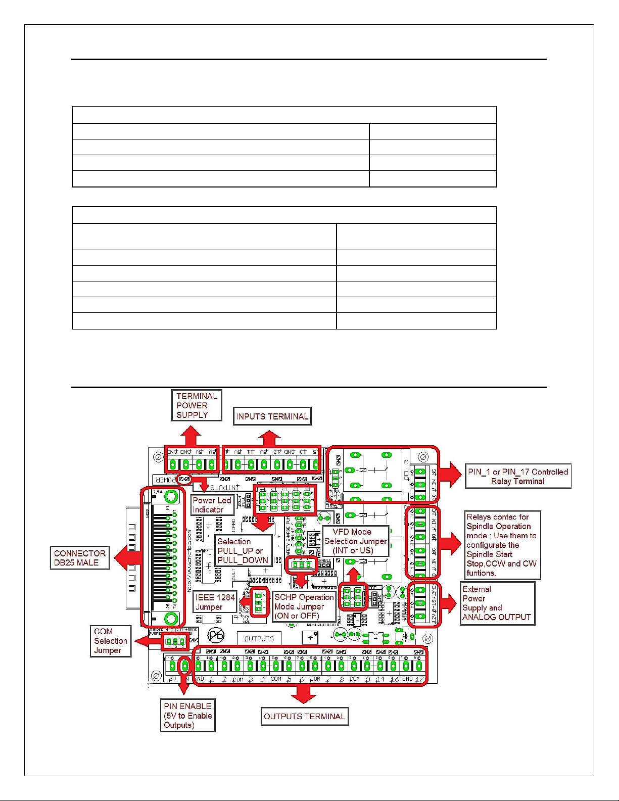
4.0 BOARD DESCRIPTION

User’s Manual
Page 3
5.0 POWER TERMINALS AND CONFIGURATION JUMPERS
Regulated +5VDC@ 1A is required to power this board.
WARNING
Check the polarity and voltage of the external power source and connect the 5VDC and
GND. Overvoltage or reverse-polarity power applied to these terminals can cause
damage to the board, and/or the power source.
5.1 Power Terminal
User’s Manual
Page 4
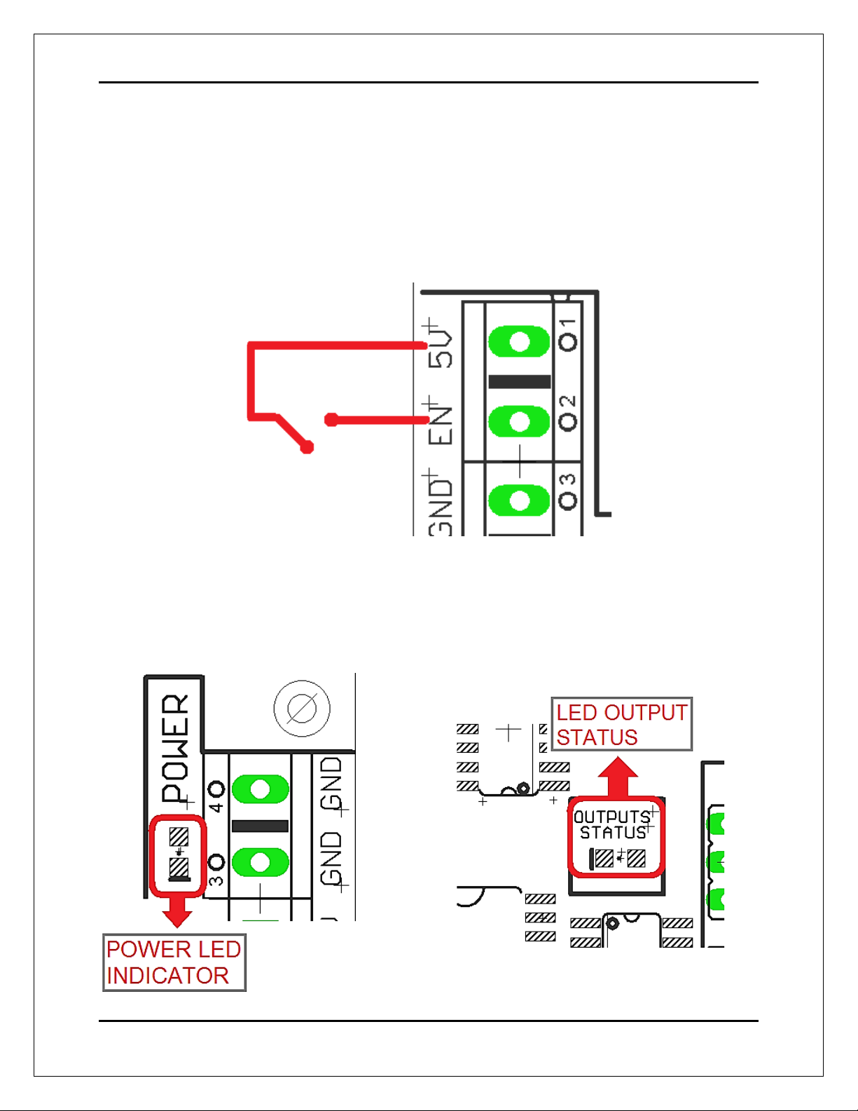
5.2 External Enable Pin.
The card must be provided with a 5VDC signal to enable operation. This feature has
been added to externally control the status of the outputs. An external switch or a Safety
Charge Pump can be added to provide the enabling signal. When the enable signal is
not present, output signals send high impedance state. If this function is not required, a
jumper can be placed between +5vdc and the EN terminal. It has an internal 4.7kOhm
pull-down resistor.
5.3 Led Indicator
The power LED lights indicate that the system is ready but disabled. When Status
LED, (Green LED) lights, it indicates that the system is enabled.

User’s Manual
Page 5
5.4 Safety Charge Pump “SCHP”. (Pin 17).
This board takes advantage of Mach ability to send a specific frequency through one of
the pins of the parallel port when the program is in control of the system. CNC
machinery can be very dangerous, and you could have a risk of the machine doing
something different that what you intend the machine to do if the program loses control
of your system. Mach can be programmed in a way, so when it is “in control”, it delivers
a 12.5 KHz signal through one of the pins. This card lets you use this signal to work as
an On/Off switch for your system, enabling a powerful safety system for your
equipment. If you ever had windows crash on you, then this card is for you. The port
can also do weird things while the system is coming up, or down.
For Configuring the Charge Pump in Mach X: Use the dialog Config / Ports and
pins / Output Signals. Enable the Charge Pump output and configure it as is shown in
the Fig. 8 Next, press the apply button.
Charge Pump configuration
User’s Manual
Page 6
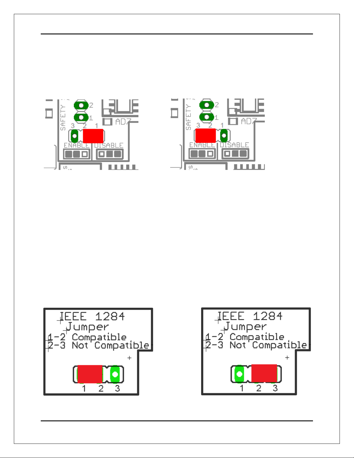
Selecting the SCHP operation mode
The Safety Charge Pump can be activated or deactivated depending on the jumper
position
1-2: SCHP OFF 2-3: SCHP ON
Note: When the Safety Charge Pump is activated, the EN terminal is active and a valid
SCHP signal is present, pin 17 will go high. This high signal can be used to enable
other external devices, such as enabling other Breakout Boards, or relays that would
enable servos, VFDs, contactors etc….
5.5 Controller selection jumpers (IEEE1284)
Some motion controllers are not IEEE1284 compatible, set the jumper to select the
compatibility.
Compatible (IEEE1284) Not Compatible (IEEE1284)

User’s Manual
Page 7
US MODE (US)
INPUTS
RELAYS
PWM (Pin 14)
REV (Pin 16)
REL 1
REL 2
ON
ON
OFF
ON
ON
OFF
ON
OFF
OFF
ON
OFF
OFF
OFF
OFF
OFF
OFF
6.0 VARIABLE SPEED CONTROL
This function lets you control your spindle with PWM signal. It converts the PWM signal
into an analog (0-10VDC).
This function can also be used on many DC motor controllers by replacing the
potentiometer that controls the speed.
Requirements:
It requires a power supply external +12VDC@ 30mA for the analog output
WARNING: To keep the output signals optoisolated, these must not have
common ground or connections to current with other circuits you are using.
You will require a voltmeter to fine tune your system.
Wiring:
Before connecting anything, please be sure to read your VFD’s manual and make sure
you understand all the safety issues.
Spindle uses Pins 14 for step (PWM at 1000hz) and 16 for Dir.
6.1 Operation Mode Jumper
This jumper allows selecting the way how the relays are activated when a PWM signal and REV
signal are present in the inputs terminals. See the tables below.
MODE - US
MODE - INT
INTERNATIONAL MODE (INT)
INPUTS
RELAYS
PWM (Pin 14)
REV(Pin 16)
REL 1
REL 2
ON
ON
ON
ON
ON
OFF
ON
OFF
OFF
ON
OFF
ON
OFF
OFF
OFF
OFF
User’s Manual
Page 8
Relay 1 and 2
They can be used to control the VFD. The relay specifications are shown in this table.
ELECTROMECHANICAL RELAYS SPECIFICACTIONS
Maximun Current (AC)
7A@240VAC; 10A@125VAC
Maximun Current (DC)
15A@524VDC; 10A@28VDC
Electromechanical Relays Specifications
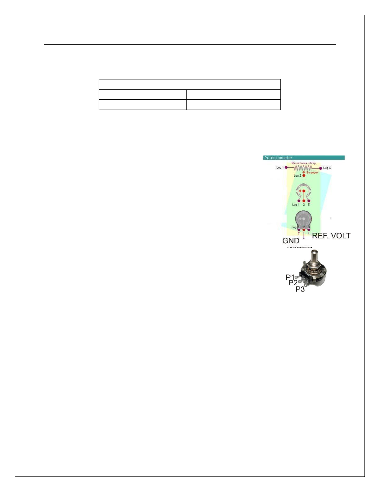
Replacing a Potentiometer:
This circuit can be used to replace a potentiometer of DC moto.
These speed controller circuits are very commonly used by
SIEG, KB Electronics, and many other oriental machines.
Before explaining how to do it, please first keep in mind that it
can be done if the voltage that goes through the pot is +12vdc
or less. This circuit cannot be used for AC currents.
In most cases the terminals that go to the potentiometer will
carry these signals:
P1 = GND
P2 = WIPER
P3 = REFERENCE VOLTAGE
These are the steps for replacing a potentiometer:
1.
Measure the voltage difference between P1 and P3. Make sure it measures
under +12vdc.
2.
Fine tune the analog output to the output voltage you got from step 1.
3.
Connect the ground from the analog output to the ground of thepotentiometer
(P1).
4.
Connect the analog output to the wiper connection of the potentiometer (P2).

User’s Manual
Page 9
6.2 Electromechanical relays. (Pin_1 or Pin_17)
This RELAY is activated with the PIN_1 or PIN_17, set jumper as sample in the image.
PIN_1 PIN_17
Mechanical relays are very flexible because they can be used for AC or DC and come
with NO and NC (Normally Open and Normally Closed) positions. The relay
specifications are shown in the below table.
ELECTROMECHANICAL RELAYS
SPECIFICACTIONS
Maximun Current (AC)
7A@240VAC;
10A@125VAC
Maximun Current (DC)
15A@524VDC;
10A@28VDC
6.3 Using the COM configuration jumper.
This is for selecting the value to get at the COM terminals found next to step and
direction terminals (Pin 2-9). Some drivers expect a ground, and others expect +5vdc.
There is a jumper that allows you to select +5VDC or GND for the COM pins.
1-2: COM= 5V 2-3: COM= GND
User’s Manual
Page 10
7.0 FUNCTIONAL BLOCK DIAGRAMS
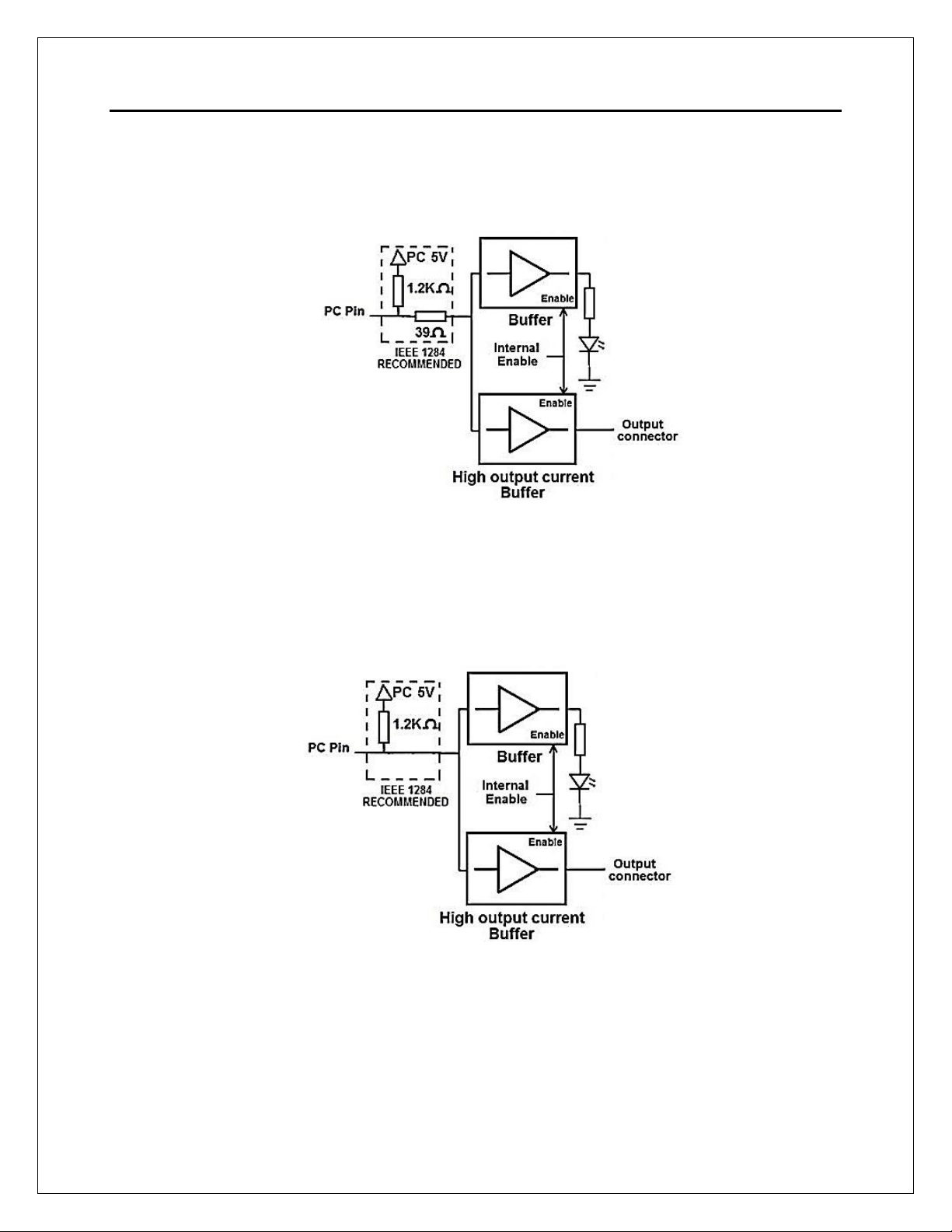
7.1 Outputs 2-9 simplified functional block diagram
Parallel Port circuit uses IEEE 1284 standard recommendation. The LEDs for the pins
are driven by a separate buffer.
7.2 Outputs 1, 14, 16 and 17 simplified functional block diagram
Note: “Internal Enable” = “External Enable Pin” AND (“SCHP” OR “Bypassed SCHP”)
The “Internal Enable” is the result of an AND Operation between the “External Enable Pin” and
the SCHP operation mode selected by the user.
Note: All Outputs will be deactivated if the board is not connected to the PC parallel
port.
User’s Manual
Page 11
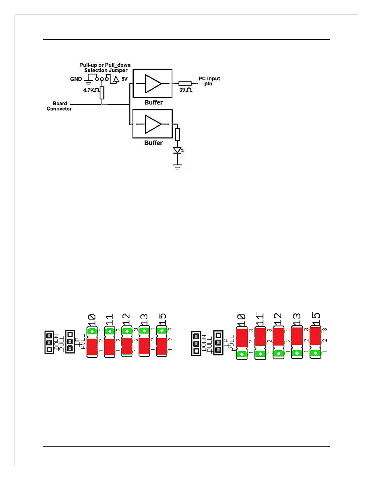
7.3 Input simplified functional block diagram
Simplified functional block diagram for the inputs
7.4 Selection Jumper PULL-UP or PULL-DOWN
Pins 10,11,12,13 and 15 can be set to pull-up or pull-down by selecting the jumper in the
appropriate position.
The input pins can be set to be pulled up or down with a 4.7Kohm resistor.
1-2: PULL-UP 2-3: PULL- DOWN
Pull up/down resistors determine the normal status of a pin when left in the air (not
wired or circuit open). If active high it sends a high to the controller and it requires a low
or ground or 0vdc to make it change states. If active low, then it sends a low to the
controller and it requires +5vdc from the board to make it change state.
User’s Manual
Page 12
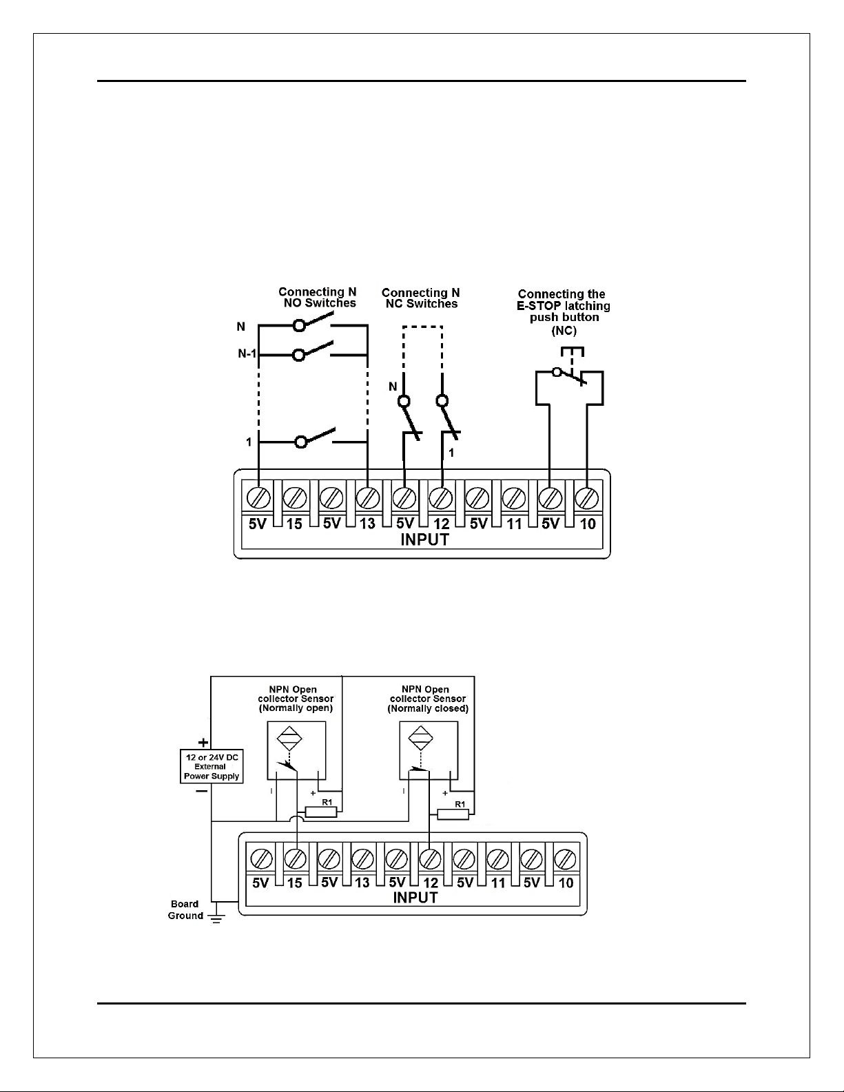
8.0 WIRING DIAGRAMS
While this board supports only TTL +5VDC signals, different kind of sensors, switches
using different voltages can be connected using the diagrams that follow:
Note: The below wiring diagrams are examples, any input can be used for the connections.
Note. The bellow wiring diagrams require setting the inputs to use pull-down resistor.
8.1 Connecting Switches or push button.
Wiring diagram to connect switches
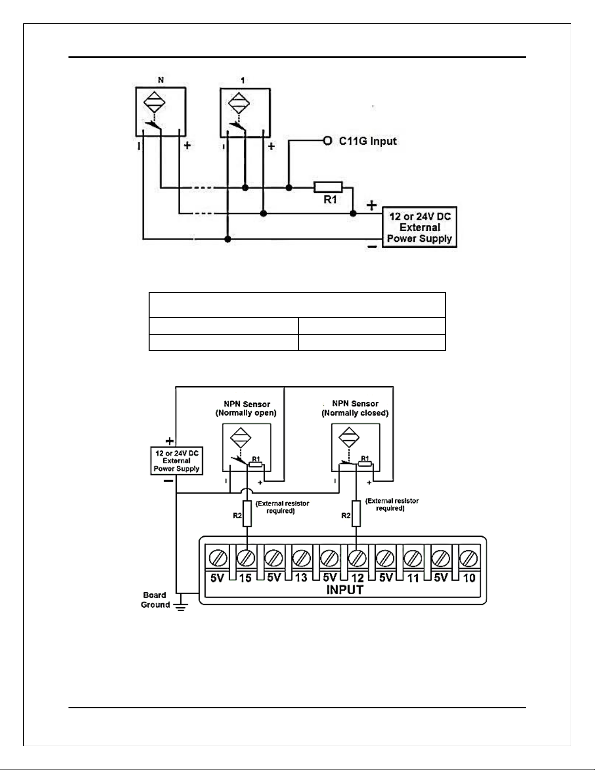
8.2 Connecting NPN sensors.
Wiring diagram to connect NPN open collector proximity sensors
User’s Manual
Page 13
Wiring diagram to connect in parallel NPN open collector proximity sensors
Connecting NPN open collector proximity sensor with
the C11GS
R1 Value (12V)
R1 Value (24V)
Aprox. 10KΩ
Aprox. 25KΩ
Wiring diagram to connect NPN proximity sensors with internal pull up resistor
Some NPN proximity sensor has a pull-up resistor (R1) internally. It is necessary to
know its value in order to connect safely the sensor with the BOB. Follow this
recommendation:
User’s Manual
Page 14
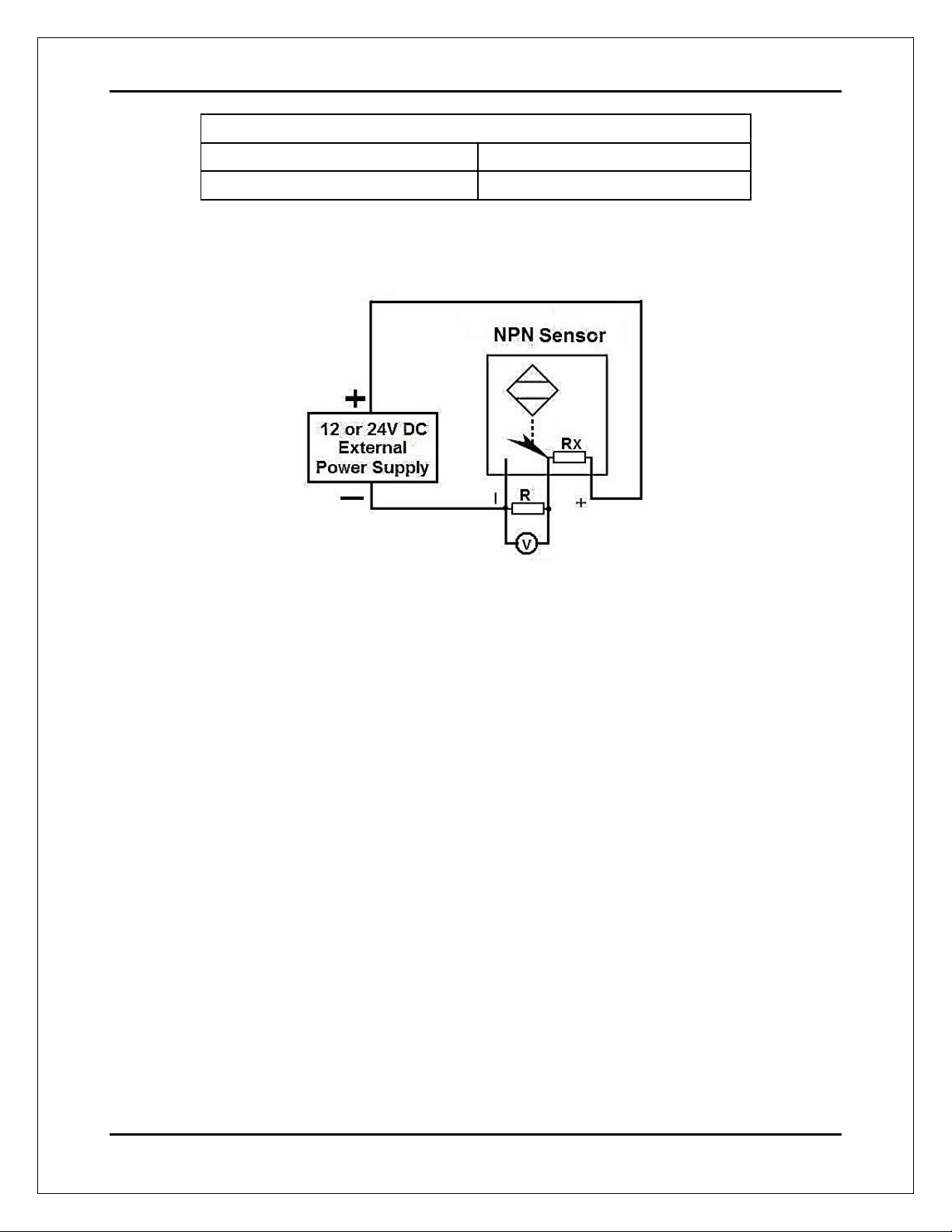
Connecting NPN open collector proximity sensor with the C11GS
(R1+R2) Value (12V)
(R1+R2) Value (24V)
Aprox. 10KΩ
Aprox. 25KΩ
Calculating the R1 value
Note: Rx is the unknown resistor value.
RX = VEX. (R/V) - R (1)
Where:
VEX is the external power supply voltage
V is the voltage across the R resistor
An external resistor and a voltmeter are required to calculate the internal resistor (Rx) value.
Note. The user should know the R value to do this operation. A 4.7KOhm @ 1/2W is
recommended.
SAMPLE: if you are using a 12V power supply (VEX), and using a 4.7KOhm as external
resistor (R), then the voltage across R should be 6V, using the equation 1, the Rx value is
4.7KOhm.
User’s Manual
Page 15
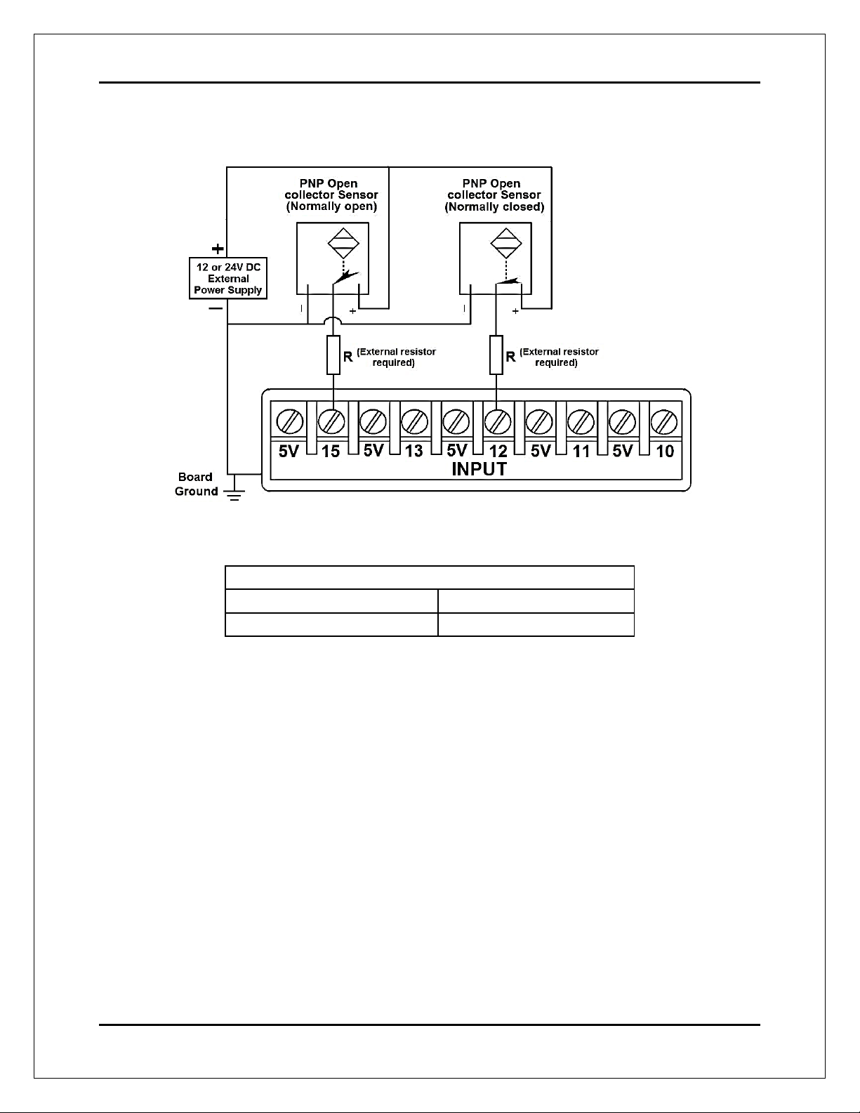
8.3 Connecting PNP sensors.
Wiring diagram to connect PNP proximity sensors
Connecting PNP proximity sensor with the C11GS
R Value (12V)
R Value (24V)
Aprox. 10KΩ
Aprox. 25KΩ

User’s Manual
Page 16
9.0 DIMENSIONS
All dimensions are in Millimeters
Fixing holes (3.8mm).
DISCLAIMER:
Use caution. CNC machines can be dangerous machines. Neither DUNCAN USA, LLC
nor Arturo Duncan are liable for any accidents resulting from the improper use of these
devices. This board is not a fail-safe device and it should not be used in life support
systems or in other devices where their failure or possible erratic operation could cause
property damage, bodily injury or loss of life.
Other manuals for C11G
3
Table of contents
Other CNC4PC Motherboard manuals


