Co-Motion Cycles Co-Pilot Single User manual

Co-Pilot Single
Travel Bikes
Packing and Traveling
with your Co-Motion bike
Pinion Co-Pilot
Eugene Oregon
USA
Toll free 1-866-282-6336

2
Congratulations!
The Co-Motion Co-Pilot equipped with a Pinion gearbox is
an excellent choice for world travel. These instructions will
help you feel comfortable with packing and assembly of your
new bike. Soon enough you’ll be looking for more destina-
tions to take your bike with you.
Your Co-Pilot bike is designed to fit into a 26 x 26 x 10”
travel case. These dimensions are important because they
fall within the non-oversize bag regulations stipulated by
most airlines, saving you from additional bag fees.
Using our Co-Pilot travel case you will have room for the
complete bike plus some essentials like pedals, tools, cloth-
ing, maps and small bike bags. Keep in mind the Co-Pilot
travel case is designed to meet the airline regulations, there-
fore it won’t have room for racks, panniers or fenders.
Getting Started
The first rule here is to avoid rushing and situate yourself in
an area with enough room for you, the bike and the travel
case. You’ll need the following items, at a minimum, and
your particular setup may require additional tools:
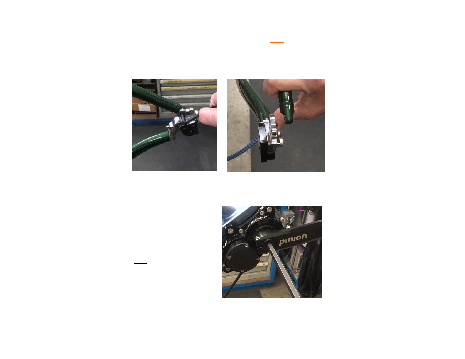
Universal spanner that fits the S&S couplers
A multi-tool or Allen tools in sizes 4mm, 5mm, 6mm
A pedal wrench for your particular pedal type
Torx T25 wrench and Centerlock rotor tool if needed
Some rags or towels to clean up grease
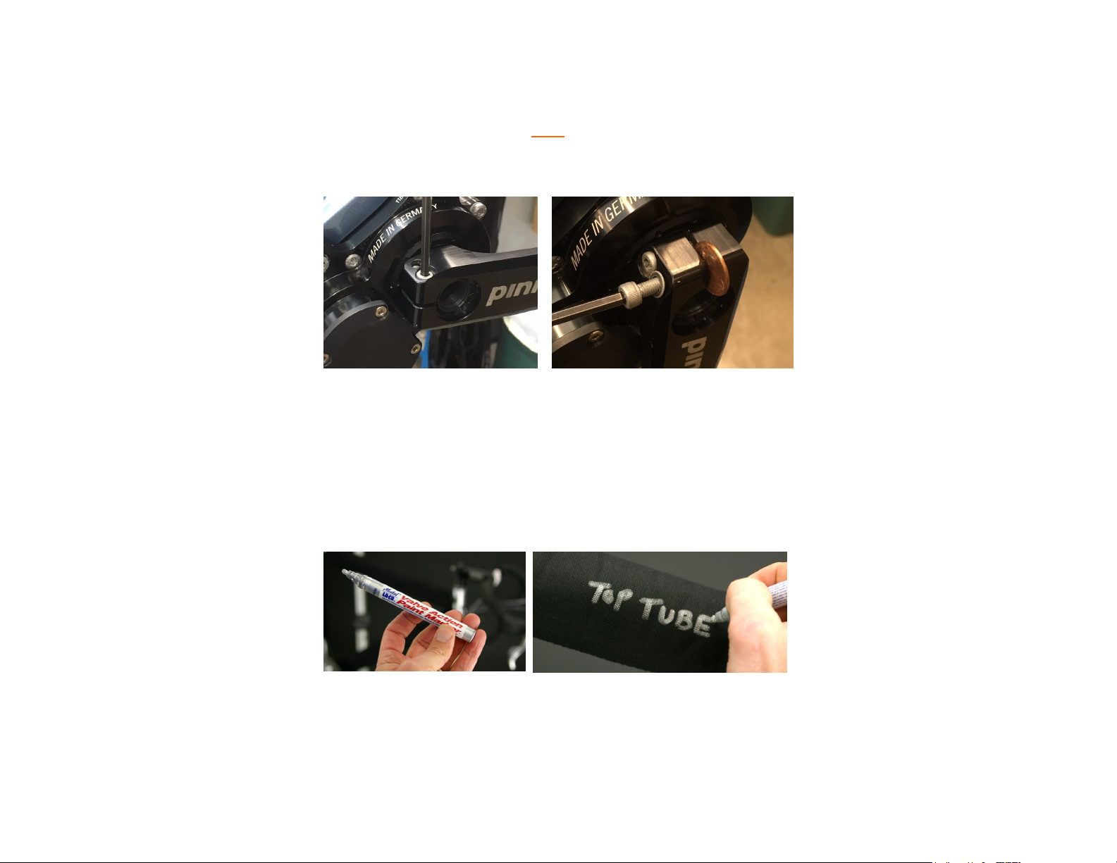
A sharp pair of scissors and paint pen
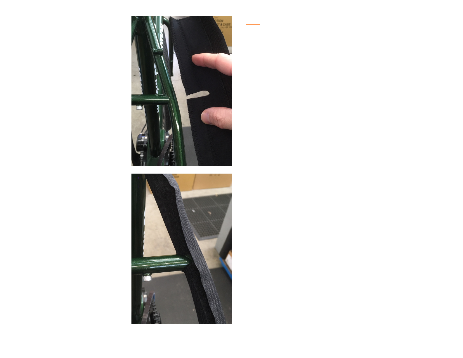
A bag of zip-ties and Padding kit ready to cut or install
Torque wrench with Allen adapter
If you’re not familiar with bicycle terms, a knowledgeable
friend or bicycle maintenance manual will be helpful.

3
Step-by-Step
Using your coupler spanner, loosen both couplers just enough
so that they will turn easily by hand. Standing over the bike
push the spanner toward the non-drive side of the bike,
counter-clockwise to loosen.
Next use the appropriate pedal wrench and remove your
pedals. (Note: the left pedal is reverse threaded. With
wrench pointed upward, both pedals loosen when rotated
toward the back of the bike. Counter-clockwise for the right
pedal, clockwise for the left pedal). Remove any water bot-
tle cages, pannier racks and all accessories like bags, frame
pumps, lights and computers.

4
Use the appropriate Allen
wrench to remove the handle-
bar stem’s faceplate. Replace
the faceplate and bolts after
removal so that the parts don’t
get lost.
Loosen the gearbox cable
housing adjusters on the upper
section of the down-tube. Once
they are removed the cables
and adjusters can be removed
from the frame.
Use an Allen wrench to loosen the seat post clamp and remove
the seat post with saddle attached. Turn the bolt counter-
clockwise to loosen but do not remove the bolt. After the post
has been removed re-tighten the bolt slightly so it won’t come
out during transit.
Use your cable splitters to separate the gear box cables and
rear brake cable. Note: turn only the female side of the splitter
(side with no set screws) counter clockwise to remove.

5
Fork Removal / Installation
Before removing the fork, you will need to remove the disc brake
caliper and cut the zip-tie securing the brake housing to the fork
blade.
Next remove the stem’s top cap, typically with a 5mm Allen.
Loosen the stem’s pinch bolts with an Allen wrench and remove
the stem. Take careful notes of the orientation of spacers and
headset parts. You will need this for installation later.
Push the top of the steerer tube down
and out of the frame. The upper head-
set parts should slide off. If the top
seal is tight, use something to drive the
steerer tube down. Any solid but non-
damaging item will work. Note: do not
use a hammer for this process.
Now you can remove the
wheels and fenders if in-
stalled on the frame and
fork. We recommend re-
moving the disc brake ro-
tors from the hubs to en-
sure they stay true during
travel. You will need either
a Torx T25 wrench or a
Centerlock tool depending
on your rotor type.

6
Using a Torx T25 wrench loosen the rear dropout bolt to remove the
Gates belt or chain. Gently push the seat-stay tube and dropout
away from each other until there is just enough room to slip the belt
through the triangle. Replace the bolt and tighten. Note: it is not nec-
essary to adjust the sliding dropouts during wheel removal or installa-
tion. These are used for initial tension or maintenance only. The belt
tension will be restored when the rear wheel is re installed during as-
sembly.
To ease in packing the bike
we recommend removing
the Pinion crank arms. Start
with removal of the spindle
cap bolts using a 8mm Allen
wrench on both crank arms.
Note: The bolt torque spec
when installing the crank
arms during re assembly is
10 Nm for both the cap bolt
and pinch bolts.
Crank Removal / Installation
These Steps are
recommended, but
not absolutely
necessary.
Removing the
Gates belt ensures
that it will arrive
safely, however
some travelers
prefer to minimize
the time invested in
packing and
reassembly.
Crank removal is not
absolutely necessary,
however it will make
your bike fit more
easily into its case
while also minimizing
potetnial damage

7
Protecting your Co-Pilot
If your padding kit has not yet been cut to length, this is the time to
do it. Grab your scissors and paint pen. Sharp scissors are recom-
mended as the fabric is tough. The goal here is to protect each
painted surface as best as possible.
Starting on one side of the bike, loosen the two pinch bolts using a
4mm Allen wrench. Next remove only the outer bolt and re-thread
from the opposite side of the arm. Place a penny or similar object into
slot while tightening the outer bolt. Once the bolt touches the penny,
continue to turn bolt one full turn. This should open the crank arm slot
enough to allow easy removal. Note: avoid over-tightening this bolt
during crank arm removal. Replace the outer bolt to it’s normal posi-
tion and repeat steps on the other crank arm.
It is helpful to mark the padding sections with a paint pen or silver per-
manent marker (available at home improvement or craft stores). This
will help for future identification and placement.

8
With the fork removed and all accessories aside, we can
now separate the frame into two sections by fully loosening
each frame coupler. Turn toward the non-drive side of bike.
Start with the widest (5.0”) rolls of frame padding, this will
cover the larger diameter frame tubes like the top tube,
down tube, head tube and seat tube. Measure the distance
of each tube section and add 1-2.0” beyond where the cou-
pler stops. Label each section as you go and repeat the
steps for each front-triangle tube.
Take the next widest (3.75”) roll of padding and measure
correct lengths needed for the chain-stay tubes and fork legs.
It may be necessary to notch the padding on one section to
clear the disc brake tab on the fork. The remaining 2.25” wide
padding will cover the seat-stay tubes.

9
Note: When notching
the frame padding, only
cut half-way across the
width of the padding.
Also, the height of the
cut or notch should
match or be slightly less
than the height of the
obstacle. In this example
we’re cutting around the
seat-stay bridge. The
same process would be
used for a brake mount.
The padding is stretchy
so these notches don’t
need to be exact.
Shorter height cuts are
often better than taller
cuts.

10
Now we’re Packing!
Keep in mind there is not one perfect recipe for packing your Co-pilot
bike in the travel case. Frame sizes, fork sizes and handlebar types
vary greatly for each individual. However, over the years we have
learned that these basic steps apply to most coupled bikes. The fol-
lowing is just one possible way to pack your bike for airline travel.
Place the front triangle into the Co-Pilot travel case first, with head
tube oriented toward one of the corners. The center of the case
should be reserved for drive-side hub on the rear wheel.
If your total fork length is less than 26”, like the one pictured here,
you can place the fork on the opposite side of the front triangle. If it’s
longer it will need to be packed diagonally in the case., and possibly
on top of the rear wheel.
Be sure to handle the Gates
carbon belt according to their
owner’s manual for safe travel,
do not bend or twist the belt.
The owner’s manual is also a
great resource for installation,
correct tension, proper align-
ment, regular maintenance, and
how to recognize when it’s time
to replace the chain-ring, cog or
belt.

11
You can add small parts to the case like pedals, stem, drive belt, tools,
etc. Note: we strongly suggest wrapping all loose items inside bubble-
wrap padding or inside towels and spare clothing.

12
Next, place the rear wheel in the case atop the front frame section.
Deflating the tires until you achieve a snug fit. You may find the wheel
fits better with the cog facing down rather than up. We’ve inserted
hub protection caps on the top side of both hubs to help prevent
scratches and evenly distribute the load.
To help ensure the belt ring, or chain-ring, stays true during travel we
made a simple cardboard envelope with tape. Start with a square piece
of thin cardboard just larger than the diameter of the ring. Cut a wide
slot half way across the square, wide enough to clear the drive mecha-
nism. Cut another square piece of cardboard to match the first and tape
on the three longest sides. Slide the protector over the ring.
Note: we highly recom-
mend you use zip-ties or
straps to secure frame
sections to the wheels.
The goal is to prevent
frame components from
moving or shifting during
travel. Start with securing
the rear wheel to the front
triangle and fork.

13
Now you can place the rear
triangle on top of the rear
wheel, drive-side facing down.
The cardboard envelope you
created will sit on the rear
wheel.
Note: be sure to add some
padding or bubble-wrap on top
of the non drive-side crank
spindle facing up. This will help
protect the spindle and front
wheel.
With the rear triangle installed you can find the best placement for the han-
dlebars and seat-post/ saddle assembly. This may require removing the
rear triangle several times to confirm best placement for these components.
With a road drop handlebar, it’s best to tuck the bar-ends through the
spokes and under the rim of the rear wheel. In this example, the handlebars
are resting on top of the drive-side chain-stay and seat-stay tubes. So, it is
placed inside the rear triangle.
Note: After you find the
best layering method
secure the rear triangle,
handlebars and seat-
post with zip-ties or
straps to prevent any
movement of compo-
nents.

14
Once you find the best placement for the handlebars and seat assem-
bly, you can add the front wheel on top, with hub cap facing up. Re-
member to deflate the tire first. Close the case gently, massaging the
tire into the lid as you close it. Make sure that nothing is protruding or
interfering with the lid. Next, secure the zippers to confirm the case will
close properly.
Open the lid and secure the front wheel to the rear triangle with zip-ties
or straps. You may find there is additional room for other pieces of cy-
cling gear. Be sure to weigh the travel case as to not exceed the 50 lb
airline regulations. This will help avoid any over weight fees during
check in.
Finished!
You are now ready to explore our beautiful planet by bicycle! Please
don’t hesitate to contact us with any questions you have during packing
or re assembly. When navigating the airport, the Co-Pilot travel case
will roll best when pulled behind you rather than pushing it.

15
Assembly
Assembly is essentially the reverse of the packing process, and it is
very important that the following items are tightened and adjusted
properly:
Start by hand tightening the couplers first, then make sure that the
spanner hook is squarely engaged into the corresponding slot on
the sleeved nut before you begin final tightening. The couplers
should be tightened to 35 lbs. This is equivalent to 70 lbs. of pres-
sure on the end of the 6-inch spanner wrench. If you have any trou-
ble tightening the couplers, stop immediately and inspect the
threading for grit or debris. No threads should be visible when the
coupler is fully tightened. A very small amount of fluorinated Teflon
grease is recommended for lubrication. This special lube is avail-
able from the Co-Motion web site and should be applied at least
once a year. Note: S&S recommends you check tightness of these
frame couplers before every ride.
Make sure the wheel thru-axles, seat post clamp, stem bolts and
brake caliper bolts are all properly adjusted and tightened to proper
torque specs. Check every bolt twice before riding the bike to be
certain. Note: Torque specs are listed on the back page.
During crank arm re installation, make sure the splines are aligned
properly and the arms are 180-degrees opposed before tightening
the cap bolts. Note: the Pinion crank arms should only be installed
on the spline using the cap bolt to push the arm onto the splined
spindle. Do not push crank arms any farther on the spindle shaft
than what the cap bolt will provide. There should be a gap between
the arms and both the belt ring and gearbox, by design.

16
Co-Motion Cycles Inc.
4765 Pacific Avenue
Eugene, Oregon 97402
E-mail: sales@co-motion.com
Toll free: 1-866-282-6336
co-motion.com
A Word of Caution
If you are not confident of your ability to verify the proper adjust-
ment and therefore the safety of this bicycle, please have it
checked out by a professional bicycle mechanic before you ride.
We don’t want anyone to get hurt. Also, there are many good
books and classes on bicycles and their maintenance available
worldwide.
Torque Specs
Always refer to the component manufacturer’s recommended
specs for torque values. Component materials will vary along with
recommended torque specs. Often these torque specs will be
printed or laser etched on the component itself. Use a torque
wrench to ensure proper tightness and verify by hand.
Co-Motion seat-post clamp - 5 Nm
Co-Motion thru-axles - 10 Nm
Co-Motion sliding dropout bolts - 10 Nm
S&S couplers - 35 lbs.
Stem faceplate - typically 5 Nm for aluminum
Stem pinch bolts - typically 5 Nm for aluminum
Stem top cap for bearing preload - 5 Nm minimum
Pinion crank arm cap bolt - 10 Nm
Pinion crank arm pinch bolts - 10 Nm
Disc brake caliper mounting bolts - 10 Nm
Table of contents